1
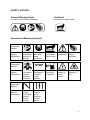
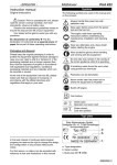
Petrol Back Pack Blower B650 USER MANUAL, MAINTENANCE INSTRUCTIONS AND SPARE PARTS READ THIS MANUAL CAREFULLY BEFORE OPERATING THE MACHINE WARNING: THIS SYMBOL INDICATES IMPORTANT SAFETY PRECAUTIONS INTRODUCTION This Back Pack Blower is a 2 stroke fast running power tool and is designed to be used in a domestic application for clearing leaves and litter from large areas. The Mitox B650 Blower is designed and manufactured to provide long life and efficient operation. Read and understand this instruction manual thoroughly before operating the machine. Specifications, descriptions and illustrations used in this manual are accurate as at the time of publication, but are subject to change without notice. Illustrations may include optional equipment and accessories, and may not include all standard equipment. Table of Contents Safety Notices……………………...…………………………………………………… 2 - General Warning Decals……………………………………………………………………………………2 - Hot Decal……………………………………………………………………………………………2 - International Warning Symbols…………………………………………………………………...2 Safety Instructions and Personal Safety Equipment……………………………3-4 - Personal Safety………………………………………………………………………………………………3 - Eye and Ear Protection..…………………………………………………………………………..............3 - Hand Protection……………………………………………………………………………………………...3 - Breathing Protection…………………………………………………………………………………………3 - Work Clothing………………………………………………………………………………………………...4 - Pre Operation Checks……………………………………………………………………………..............4 - Safe Operation……………………………………………………………………………………………….4 - Noise Control…………………………………………………………………………………………………4 - Avoid Hot Surfaces…………………………………………………………………………………………..4 Specifications……………………………………………………………………………..5 Assembly…………………………………………………………………………………..5 - Installing Blower Pipe & Control Handle…………………………………………………………………...5 Fuel Preparation and Storage…………………………………………………………6 - Fuel Safety………………………………………………………………………………………….............6 - Fuel Requirement……………………………………………………………………………………………6 - Mixing Instructions…………………………………………………………………………………………..6 - Fuel Storage…….……………………………………………………………………………………………6 Operation…………………………………………………………………………………7-8 - Starting Cold Engine…………………………………………………………………………………………7 - Starting Hot Engine…………………………………………………………….......................... …………7 - Over Choking…………………………………………………………………….……………………………7 - Stopping the Engine………………………………………………………………………………………….7 - Operating Blower……………………………………………………………………………………………..8 Maintenance…………………………………………………………………………….8-10 - Air Filter…………………………………………….………………………………………………………….9 - Fuel Filter…………………..………………………………………………………………………………….9 - Spark Plug…………………..…………………………………………………………………………………9 - Spark Arrestor..…………..……………………………………………………………………………………9 -Transporatation……………………………………………………………………………………… ………9 - Maintenance Intervals…..…………………………………………………………………………………...10 -Parts Lists…………………… ……………………………………………………………..…………………11 -Conditions of Warranty………………………………………………………………………...……………..14 1 SAFETY NOTICES General Warning Decal Hot Decal Located on top of blower housing Located on muffler guard International Warning Symbols Information Symbol Symbol Description Read and understand Operator’s Manual Information Symbol Symbol Description Wear eyes, ears and head protection Hot Surface Risk of burn Safety/Alert Finger Severing Petrol and oil mixture Beware of electric shocks Beware of fire STOP Do not use the product in places with poor ventilation Emergency / Engine “Stop” position Choke Control “Cold Start” Position (Choke Closed) Choke Control “Run” Position (Choke Open) Information Symbol Symbol Description 2 SAFETY INSTRUCTIONS AND PERSONAL SAFETY EQUIPMENT WARNING DANGER Power Blower users risk injury to themselves and others if the power blower is used incorrectly, and/or safety precautions are not followed. Proper clothing and safety equipment must be worn when operating the blower. Personal Safety This blower is very powerful and the air force will blow debris around the work area. Keep bystanders, animals, etc at least 15m away from the operational area. This product has been designed to be used as a blower and should not be used for any other purpose; doing so could result in unforeseen accidents and injuries occurring. Only approved Mitox accessories should be used with this product. Never use this blower when under the influence of alcohol, suffering from exhaustion or lack of sleep, suffering from drowsiness as a result of having taken medication, or at any time when your judgement might be impaired or when you might not be able to operate the blower properly and in a safe manner. Never allow children or anyone unable to fully understand the instructions given in this manual to use the blower. When planning your work schedule allow plenty of time to perform the work and allow plenty of time for rest. Limit the amount of time you continually use the blower to 30 – 40 minutes per session, and take 10 – 20 minutes rest between each work session. Do not run this blower indoors, exhaust gases contain harmful carbon monoxide. Eye and Ear Protection Always wear eye protection (goggles or visor) and ear protection (ear defenders) that meet CE requirements whenever the blower is operated. Hand Protection Always wear non-slip heavy duty work gloves, ideally with anti vibration gel filling to reduce machine vibration to the operating hand. Breathing Protection Wear a facemask to protect against dust during dry periods, and to prevent against inhaling harmful dust particles. 3 Work Clothing Wear durable clothing or work overalls, including long trousers and longsleeved shirts. Wear sturdy non-slip work shoes. Keep long hair away from the engine blower intake. Contain hair during work with a cap or hairnet. Pre Operation Checks Before beginning work each component of the blower should be checked to make sure that it is in proper safe working order. Check there are no loose screws, nuts or bolts, fuel leaks, ruptures, dents, or any damage which might interfere with safe operation. Safe Operation Before beginning work carefully check the work area and remove any dangerous or potential hazards such as stones, or metal objects. Keep bystanders and animals at least 15m from work area whilst the blower is in use. Never use this blower without fully reading and understanding the safety and operational instructions. Do not point the blower pipe at bystanders or animals. Keep a firm grip of the blowing tube to direct the air-flow. Maintain a safe footing and balance at all time. Do not stand on slippery, uneven, or unstable ground. Do not work in dangerous positions, for example from a ladder. Do not perform maintenance or assembly whilst the engine is running. Noise Control Only operate the blower during appropriate daylight hours. Never use a higher engine speed than necessary to perform the blowing task. The higher the engine speed the louder the blower noise, and the greater the blower vibration. Avoid Hot Surfaces During operation the muffler guard and surrounding area will become extremely hot. Avoid contact during use and immediately after operation to prevent the risk of burning. Always keep exhaust area clear of flammable debris. Allow the engine and muffler to cool completely before performing any maintenance work. 4 SPECIFICATIONS Model …………………….. B650 Length……………………. 465mm Width……………………… 365mm Height…………………….. 525mm Net Weight……………….. 11kg Engine Type……………… Air cooled, two-stroke, single cylinder petrol engine Carburettor……………….. Diaphragm Ignition System………….. Flywheel Magneto, capacitor discharge ignition type Spark Plug………………… NGK BPMR7A Gap (0.6:0.7) mm Exhaust System…………. Spark Arrestor Muffler Fuel……………………….. 30:1 Mixed (Unleaded Petrol 95RON and Two-stroke Oil) Fuel Tank Capacity………..1.6L Idle Speed………………… (2500±250)r/min Wide Open Throttle Speed (6800±150)r/min Displacement…………….. 63.3cc (3.68cu.in) Bore……………………….. 48.0mm (1.89in) Store………………………. 35.0mm (1.38in) ASSEMBLY Installing Blower Pipe & Control Handle 1. 2. 3. 4. 5. 6. Slide control grip (G) onto handle (I) and secure with allen screw and nut. Assemble clamps (B) onto both ends of flexible pipe (C) and tighten. Assemble flexible pipe (C) to elbow (A) on blower. Assemble straight pipe with swivel (D) to flexible pipe (C). Loosen wing nut on control handle assembly (H) and fit to pipe (D). Align notches in control handle assembly (H) with pegs on pipe (D). Handle should be angled away from the operator. 7. Assemble straight pipe (E) onto pipe (D). 8. Assemble straight pipe (F) onto pipe (E). (G) (I) (A) (H) (B) (A) (C) (B) (D) (B) (H) (F) (E) (D) (C) (E) (F) 5 FUEL PREPARATION & STORAGE Fuel Safety The engine of this blower is designed to run on a two-stroke fuel oil mixture, this fuel is highly flammable. Never store cans of fuel or refill the fuel tank in a place where there is a source of heat or fire, which might ignite the fuel. Do not smoke while operating the blower or refuelling. Keep naked flames away from the blower at all times. When refilling the fuel tank always stop the engine and carefully make sure there are no sparks or open flames anywhere nearby before refuelling. If any fuel spillage occurs during refuelling use a dry rag to wipe any fuel which has been spilled before starting the engine. After refuelling screw the fuel cap back tightly on to the fuel tank and carry the blower to a position at least 5m away from where it was refuelled before starting the engine. Fuel Requirement This engine is lubricated by oil mixed into petrol. Follow the instructions below to prepare a mixture of unleaded fuel (95 RON) and semi-synthetic 2-stroke oil that meets specification of APITC, ISO-L-EGC, JASO FC (low smoke) oil. Recommended mixing ratio is 30:1. Mixing Instructions 1. Use fresh unleaded petrol (95RON) and semi-synthetic oil specially made for high performance 2-stroke engines. Mix at a ratio of 30 parts petrol to 1 part oil. 2. By using 2-stroke oil specially made for high performance 2-stroke engines you will reduce the formation of ash and carbon deposits on the spark plug, piston, exhaust muffler, and cylinder, as well as reducing emissions of harmful exhaust gases. 3. Fuel with no oil (raw petrol) will cause severe damage to the engine which is not covered by the manufacturer’s warranty. 4. Oil for 4 cycle engines should not be used as a 2-stroke lubricant as it can cause fouling of the spark plug, exhaust port blocking, piston ring sticking, and other internal damage. Fuel Storage 1. When storing the blower for a period of more than one month, empty the fuel tank and run the engine to empty the carburettor of fuel. 2. 2-stroke fuel can cause deterioration of rubber and/or plastic components during prolonged storage if not emptied from the blower. 3. Mixed 2-stroke fuel which has been left unused for a period of one month or more may damage the carburettor and result in the engine failing to start or operate correctly. 4. It is important to only use good quality, fresh fuel mixture. 6 NOTE To set the throttle to half speed, pull the throttle lever back, then push and hold the throttle lock button (E) whilst releasing the throttle lever. OPERATION Starting Cold Engine 2. (A) 1. (E) (B) (C) (D) 1. Set ignition switch (A) to position 1 (ignition on). 2. Prime carburettor priming bulb (C) until fuel circulates from tank into carburettor. 3. Push choke control (B) to the closed position (down for closed, up for open). 4. Set throttle at half speed (see note). 5. Place blower on firm ground, grip the frame handle with left-hand and pull starter handle (D) with right-hand. 6. Caution do not pull starter-cord all the way out, and do not let go of starter handle when cord is extended, this can damage starter mechanism. 7. When the engine has fired, set choke lever (B) to the open position and pull starter handle (D) again to start the engine. 8. Allow engine to warm up before using full throttle. Starting Hot Engine 1. 2. 3. 4. Set ignition switch (A) to position 1 (ignition on). Set choke control (B) to open position. Set throttle control to half speed (see note). Pull starter handle (D) until engine runs. Over Choking 1. Should the engine become flooded due to over choking, set the ignition switch (A) to off (position 2), unscrew the spark plug, wipe it dry or replace, and pull the recoil starter several times without the spark plug in place and with the choke in the open position. This will help to ventilate the combustion chamber. Stopping the Engine 1. Set the throttle lever to the idle position and allow the engine to idle. 2. Switch the ignition switch (A) to position 2 (off). 7 Operating Blower Read the Safe Operation section on page 4. 1. 2. 3. 4. Always allow the engine to warm up at fast idle before operating at full throttle. Set engine speed with throttle lever. Use lower engine speed to blow dry leaves from walkways, patios, drives, etc. Additional engine speed may be necessary to clear grass and leaves from lawns, or flower beds. 5. High speed may be necessary to move gravel, dirt, snow, cans, debris from driveways, etc. To avoid engine damage due to over revving, do not block the blower pipe opening. Never use higher engine speed settings than necessary to perform the task. Higher engine speed causes greater noise, increased vibration and dust. MAINTENANCE The blower is designed to provide many hours of trouble free operation. Regular scheduled maintenance is required to maintain operational efficiency. For additional maintenance support, consult your supplier (service dealer). 1. Always stop the engine and allow it to cool before performing any maintenance or checking procedures. 2. Disconnect the spark plug to prevent accidental starting when carrying out routine maintenance. Inner Filter Air Filter “Foam” Pre Filter 1. Blowers often work in high dust conditions, which will contaminate the air filter resulting in loss of power. 2. After each use of operation, remove the air filter cover and remove any debris. 3. Remove pre-filter (black foam) and clean in warm soapy water, thoroughly dry and lightly oil with SAE 30 grade oil. 4. Inspect inner filter and replace if necessary, do not attempt to clean with petrol or water. 5. When reassembling air filter assembly always ensure filters fit correctly and cover seals correctly. 6. Never use blower without the air filter, or with a contaminated or damaged air filter or if the air filter case, or air inlet pipes are damaged as this will lead to premature engine failure. 8 Cylinder Cooling Fins The engine cooling fins can become clogged with debris that will cause overheating of the engine. Periodically check cooling fins and remove any debris. Fuel Filter Using a wire hook, remove fuel filter from the fuel tank and replace as necessary. Spark Plug Reset electrode gap to 0.6 – 0.7 mm, or replace spark plug with NGK BPMR7A as necessary. 0.6 - 0.7mm Spark Arrestor Carbon build up in the exhaust muffler can cause reduced performance and overheating. Remove and clean the spark arrestor screen regularly to remove carbon deposits as follows: 1. Disconnect spark plug lead from spark plug 2. Remove the two spark arrestor screen screws 3. Remove the spark arrestor holding plate and spark arrestor screen 4. Inspect and remove any carbon build up from the spark arrestor screen with a wire brush, or replace the spark arrestor screen 5. Reassemble the spark arrestor holding plate and spark arrestor screen. 9 IMPORTANT After every use, check that all nuts, bolts and screws are securely fastened and tighten if necessary. In the event of an accident, breakdown or blockage, ensure the engine is turned off before any work is carried out to rectify this. Make sure the engine has stopped and is cool before performing any service to the machine. Contact with moving parts or hot muffler may result in a personal injury. Always wear heavy-duty gloves when handling the blades. TRANSPORTATION Never transport the blower with the engine running. An engine that is running could be accidently accelerated causing the fan to engage. Ensure the blower is secure when transporting in a vehicle and the tank is drained of fuel. MAINTENANCE INTERVALS I = Inspect, C=Clean, R=Replace Component/ System Air Filter Before Use Daily Every 4 Hours 3 Month or 50 Hours 6 month or 100 Hours Annually or 200 Hours I+C I+C I+C R R Fuel Filter Cylinder Cooling Fins I+C Muffler Spark Arrestor Recoil Rope I Spark Plugs Screws/Nuts Bolts/Fixings I R I+C I+C I R I+C I R R I Failure to adhere to recommended maintenance intervals can lead to premature failure of the blower and will invalidate the manufacturer’s warranty. 10 CONDITIONS OF WARRANTY The manufacturer warrants the product against faulty materials and workmanship for a period of 2 years from the date of first purchase to the original purchaser. The warranty is applicable when the product is used in a “home owner” application. If products are used for commercial or professional purposes, the warranty period is for 3 months from the date of first purchase. Warranty does not extend to failure due to fair wear and tear. The manufacturer undertakes to replace any spare parts that are classified as defective by an appointed Mitox service dealer. The manufacturer will not accept liability for the replacement of the machine, either partially or wholly, and/or consequential damages. Warranty does not cover failure due to: Insufficient maintenance. Incorrect fuel mixture and stale fuel. Abnormal use or accidental damage. Incorrect assembly, adjustment or operation of the product Spare parts that are subject to wear e.g. safety parts, guards, deflectors, spark plugs, filters, blower tubes, harnesses etc. Neither does warranty extend to: Freight and packing costs. Use of non-genuine spare parts i.e. those from another manufacturer. Use of the machine for any other purpose than that for which it was designed. Use and maintenance of the machine in a manner not described in the owner’s manual. As part of our policy of continuous product improvement, we reserve the right to alter or amend this specification without notice. As a result, the product may differ from the information contained herein, any alteration will be implemented without notice if it is classified as an improvement to the above specification. READ THE MANUAL CAREFULLY BEFORE OPERATING THE MACHINE When ordering spare parts, please quote the part number, this can be found in the parts list included in this manual Retain the receipt of purchase without which no warranty can be offered. Distributed by Mitox Garden Machinery Wincanton Business Park Wincanton Somerset BA9 9RS www.mitoxgm.co.uk 11