1
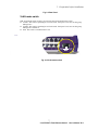
Live-FSH16T+
Fast Ethernet Switch
16 × 10/100Mbps
NWay 10/100BASE-TX
Fast Ethernet Switch
with VLAN function
User’s Manual
Live-FSH16T+ V.2.1
October , 2002
Copyright © OvisLink Corp.
Trademarks
All rights reserved.
OvisLink and OvisLink Logo are registered trademarks of OvisLink Corp. Other product
names and company names are trademarks or registered trademarks of their respective
owners.
FCC Warning
This equipment has been tested and found to comply with the requirements for a Class A
digital device, pursuant to Part 15 of the FCC Rules. These requirements are designed for
reasonable protection against harmful interference when the equipment operating in a
commercial environment. This equipment can generate and radiate electromagnetic energy
and, if not installed and used in accordance with this guide, may cause significant
interference with radio communication. Operation of this equipment in a residential area is
likely to cause interference to household appliances, in which case the user will be required
to amend at his or her own expense.
CE Mark Warning
This is a Class A product. In a domestic environment, this product may cause radio
interference, in which case the user may be required to take adequate preventive measures.
Disclaimer
Contents in this manual are subject to changes without prior notice.
About this User’s Manual
This User’s Manual aims at helping users to know the key features of
Live-FSH16T+ Fast Ethernet Switch and to install it in a 10/100BASE-TX
Fast Ethernet Local Area Network (LAN).
Table of Contents
Table of Contents
TABLE OF CONTENTS ........................................................................................I
1
PRODUCT OVERVIEW ........................................................................1
Introduction....................................................................................................................... 1
16× 10/100Mbps ports Fast Ethernet Switch with Per-port VLAN function ................. 1
Port-based VLAN for Instant Connectivity and Workgroup Privacy............................. 1
Per-port VLAN Configuration via a selection switch..................................................... 1
Store-and-Forward Architecture against Packet Loss..................................................... 1
Active Flow Control ....................................................................................................... 2
Full Wire Speed .............................................................................................................. 2
System/Port Status Information at a Glance ................................................................... 2
What is VLAN? ................................................................................................................. 2
Defining VLAN .............................................................................................................. 2
Port-based VLAN ........................................................................................................... 2
Table Maintenance via Signaling.................................................................................... 3
Product Features............................................................................................................... 4
Basic Features ................................................................................................................. 4
Advanced Features.......................................................................................................... 4
2
PREPARATION BEFORE INSTALLATION.........................................5
Unpack the Package.......................................................................................................... 5
The Front Panel................................................................................................................. 6
The Rear Panel.................................................................................................................. 6
i
Live-FSH16T+ Fast Ethernet Switch
User’s Manual V2.1
Table of Contents
Station Ports (Port #1 to #16).......................................................................................... 6
DC Power Jack................................................................................................................ 6
VLAN mode switch ........................................................................................................ 7
3
INSTALLATION OF THE SWITCH.......................................................8
Quick Installation.............................................................................................................. 8
3 Steps to Quick Installation ........................................................................................... 8
Desktop Installation .......................................................................................................... 8
Installation on Wall........................................................................................................... 9
Cabling Requirements ...................................................................................................... 9
Cable requirement for 100BASE-TX Port...................................................................... 9
Straight-through cabling ................................................................................................. 9
Connecting to Power....................................................................................................... 11
4
EXPANDING YOUR NETWORK ........................................................12
Connectivity Rules .......................................................................................................... 12
10 Mbps Connection (10BASE-T) ............................................................................... 12
Twisted-pair 100Mbps Connection (100BASE-TX) .................................................... 12
Connecting to another Switch/Hub ............................................................................... 13
Straight-through Cable Connection for Switch-to-Switch/hub Connection ................. 13
Transmission Modes ....................................................................................................... 14
Station Ports (10/100BASE-TX Transmission)............................................................ 14
LAN Micro segmentation through Switching Technology.......................................... 14
Benefits of VLAN ............................................................................................................ 14
Advantage of VLAN Switching over Routing.............................................................. 14
Virtual Workgroups ...................................................................................................... 15
Centralized Server Farms.............................................................................................. 15
ii
Live-FSH16T+ Fast Ethernet Switch
User’s Manual V2.1
Table of Contents
Higher Performance and Reduced Latency .................................................................. 15
Ease of Administration ................................................................................................. 15
Saving Costs.................................................................................................................. 15
Routing between VLANs.............................................................................................. 15
Security ......................................................................................................................... 16
Reduction of Routing for Broadcast Containment........................................................ 16
Infrastructural VLANs .................................................................................................. 16
5
LED INDICATORS..............................................................................18
Comprehensive LEDs ..................................................................................................... 18
System LED .................................................................................................................. 18
Station Port LEDs ......................................................................................................... 18
Power LED ...................................................................................................................... 18
VLAN LEDs .................................................................................................................... 19
Station Port LEDs ........................................................................................................... 19
Link/Act LED ............................................................................................................... 19
FDX/Col LED............................................................................................................... 19
100M ............................................................................................................................. 19
6
VLAN CONFIGURATIONS....................................................................20
VLAN Mode Switch........................................................................................................ 20
VLAN Modes................................................................................................................... 20
VLAN1: 15-VLANs mode ........................................................................................... 20
VLAN Example using 15-VLANs mode...................................................................... 21
VLAN2: 14-VLANs mode ........................................................................................... 22
VLAN Example using 14-VLANs mode...................................................................... 22
APPENDIX A: PRODUCT SPECIFICATIONS .................................................23
APPENDIX B TROUBLESHOOTING...............................................................25
iii
Live-FSH16T+ Fast Ethernet Switch
User’s Manual V2.1
Table of Contents
Figures
Fig. 2-1 Package Content................................................................................................ 5
Fig. 2-2 Front Panel ........................................................................................................ 6
Fig. 2-3 Rear Panel ......................................................................................................... 7
Fig. 2-4 VLAN mode switch .......................................................................................... 7
Fig. 3-1 Desktop installation........................................................................................... 8
Fig. 3-2 Bottom View of the Switch (showing mounting holes).................................... 9
Fig. 3-3 10/100BASE-TX pin assignments for RJ-45 connector ................................. 10
Fig. 3-4 Pin assignments for straight-through cabling.................................................. 10
Fig 3-5 Connecting the Switch to power outlet ............................................................ 11
Fig. 4-2 Routing between VLANs through a layer-3 Switch/Router ......................... 16
Fig. 5-1 Front-panel LED indicators............................................................................ 18
Fig 6-1: VLAN Mode Switch ....................................................................................... 20
Figure 6-2 VLAN1: 15-VLANs Mode Example........................................................... 21
Figure 6-3 VLAN2: 14-VLANs Mode Example........................................................... 22
iv
Live-FSH16T+ Fast Ethernet Switch
User’s Manual V2.1
Table of Contents
Tables
Table 3-1 Cabling type for 10BASE-T/100BASE-TX................................................. 10
Table 5-1 Station Port LEDs......................................................................................... 19
Table 5-1: 15–VLANs mode ......................................................................................... 21
Table 5-2: 14–VLANs mode ......................................................................................... 22
v
Live-FSH16T+ Fast Ethernet Switch
User’s Manual V2.1
1 Product Overview
1
Product Overview
Introduction
16× 10/100Mbps ports Fast Ethernet Switch with Per-port VLAN
function
Live-FSH16T+ Fast Ethernet Switch is an auto-sensing and auto-negotiating 10/100ABSE-TX
Fast Ethernet Switch with VLAN and Priority capability. Its sixteen 10/100Mbps station ports
provide 10/100Mbps connections to Ethernet/Fast Ethernet network.
Live-FSH16T+’s unique switching fabric provides full wire speed for all ports. With auto-sensing,
Live-FSH16T+ automatically detects the speed of the devices you plug into, and routes the
incoming data to its destination. Its auto-negotiating function allows existing devices running at
different speeds to communicate easily within the same network.
Live-FSH16T+ also supports VLAN and Priority functions as briefly described in the following
sections:
Port-based VLAN for Instant Connectivity and Workgroup
Privacy
VLAN ensures instant connectivity and workgroup privacy. Since each station port can be
configured to whichever VLAN group, it offers utmost flexibility for workgroup assignment as to
ensure workgroup privacy. For those ports that join a VLAN, it offers instant connectivity without
further configuration efforts from network administrator. Members of a same VLAN group will be
included within a same broadcast domain, and will feel exactly as they are on the same network
segment (though they might not belong to the same physical network segment).
Per-port VLAN Configuration via a selection switch
With a selection switch in the back panel, user can set the switch in operate in either 14 or
15-VLANs mode. In “14-VLANs mode”, every port is in its own VLAN group sharing Port 1 and
Port 2. In “15-VLANs mode”, every port is in its own VLAN group sharing Port 2.
Store-and-Forward Architecture against Packet Loss
When network is under heavy traffic, the shared memory buffer in the switching devices might yield
incorrect detections due to overfed memory buffer. This setback can happen either when data is
transmitted in IEEE802.3x Full Duplex or Back Pressure Flow Control mode. To solve this problem,
Live-FSH16T+ utilizes a fixed memory buffer allocation with Store-and-forward transmission to
ensure an effective buffer allocation for each port.
Store-and-forward transmission controls data flow from transmitting to receiving nodes with the
receiving buffer threshold adjusted to an optimal value, thus guaranteeing against all possible packet
losses.
1
Live-FSH16T+ Fast Ethernet Switch
User’s Manual V2.1
1 Product Overview
Active Flow Control
Live-FSH16T+ Fast Ethernet Switch implements in full duplex mode a flow control that is
compliant with the IEEE 802.3x standard. While in half duplex mode, it employs an optional Back
Pressure Flow Control to stall the incoming data when port buffers are saturated. With this flow
control mechanism, it can be ensured that frames dropped during transmission are reduced to a
minimum.
Full Wire Speed
Live-FSH16T+’s Full Wire Speed feature provides high-end performance for departmental and
workgroup environments at a fraction of the cost of similar devices. Typically, this feature was
found only in high-end switches designed to handle huge corporate networks. With bandwidth needs
and network efficiency concerns, Live-FSH16T+’s switching fabric design is the perfect answer for
bandwidth enhancement solution.
System/Port Status Information at a Glance
There are 2 sets of LEDs on the front panel: System LEDs and Station Port LEDs.
The System LEDs consist of the Power, VLAN1, and VLAN2 LEDs. Power LED shows Power
On/Off status of the switch. The VLAN1(15-VLANs) and VLAN2(14-VLANs) show the VLAN
configuration status
The Station Port LEDs reveal the link status, half/full duplex transmission, 10/100Mbps speed
mode and the collision status of each station port.
For detailed LED information, refer to Chapter 5, LED Indicators.
What is VLAN?
Defining VLAN
What is VLAN? Since VLAN solutions and implementations are still very vendor-specific, to define
precisely what VLANs will certainly arouse controversy. Nevertheless, most would agree that a
VLAN can roughly be equated as a broadcast domain. More specifically, VLANs can be seen as a
group of end stations, perhaps on multiple physical LAN segments, which are not constrained by
their physical location and can communicate as if they were on a common LAN.
There are several ways to define VLAN membership: port grouping, frame tagging, MAC-layer
grouping, network-layer grouping, IP multicast grouping, etc. Live-FSH16T+ utilizes
port-grouping (port-based VLAN) for the implementation of VLAN in your network.
Port-based VLAN
Live-FSH16T+ simplified the VLAN setup by implementing the most common used VLAN
configuration with a selection switch. The two VLAN modes of Live-FSH16T+ allows users to put
each port in separate VLAN groups while able to share common resources. Users can choose either
14-VLANs or 15-VLANs group. In 14-VLANs mode, each port is in its own VLAN group with
Port 1 and Port 2 as sharing ports. In 15-VLANs mode, each port is in its own VLAN group with
Port 2. The sharing ports are ports that are shared by all VLAN groups for common resources such
2
Live-FSH16T+ Fast Ethernet Switch
User’s Manual V2.1
1 Product Overview
as Internet connection, servers, or connection to another switch.
Table Maintenance via Signaling
When an end-station broadcasts its first frame, the switch resolves the end-station’s attached port
with its VLAN membership in cached address tables. As VLAN membership changes, these address
tables can be manually updated by a system administrator at a management console.
3
Live-FSH16T+ Fast Ethernet Switch
User’s Manual V2.1
1 Product Overview
Live-FSH16T+ Fast Ethernet Switch
Product Features
Basic Features
!
!
Fast Ethernet Switch with sixteen 10/100Mbps station ports
Fully compliant with Ethernet/Fast Ethernet standards:
- IEEE 802.3 (10 BASE-T Ethernet)
- IEEE 802.3u (100 BASE-TX Fast Ethernet)
- IEEE 802.1q VLAN
- ANSI/IEEE Std 802.3 NWay auto-negotiation
!
Fixed-port configuration:
!
Easy plug-and-play installation
Port -based Home VLAN function for network topology security configuration
(Ether-FSH16T+ can be configured as 14 VLANs [Port 3 to Port 16 is in its own
VLAN group sharing Port 1 and Port 2], or configured as 15 VLANs [Each port in its
own VLAN group sharing Port 2 ] )
VLAN1/VLAN2 Selection button to enable/disable 15-VLANs/14-VLANs configuration
Store and Forward transmission to prevent packet loss
Half/Full Duplex function for all 10/100BASE-TX stations ports
Auto-sensing and auto-MDI/MDIX function for all 10/100BASE-TX station ports
Active Flow control to minimize frame drops
- 16 × 10/100 Mbps auto-sensing and auto-negotiating ports (Port #1 ~ 16)
!
!
!
!
!
!
- Half Duplex: Back Pressure control
- Full Duplex: IEEE 802.3x compliant flow control
!
Comprehensive LED indicators for system/port status monitoring:
System LEDs
- Power (green) LED to indicate power on/off status
- VLAN1 (yellow) LEDs to indicate the status of 15-VLANs configuration
- VLAN2 (yellow) LEDs to indicate the status of 14-VLANs configuration
Station Port LEDs (for port 1 ~ port16)
- Link/Act (green) LEDsto indicate linking status and activity in 10/100Mpbs mode
- FDX/Col (yellow) LEDs to indicate Half/Full Duplex transmission and collision status
- 100M (red) LEDs to indicate 100 Mbps speed
!
Cabling distance up to 100 meters for twisted-pair cable
Advanced Features
VLAN
!
!
Port-based VLAN support:
Port 1 and Port 2 can be configured as overlapping port via VLAN mode switch on the
back panel.
4
Live-FSH16T+ Fast Ethernet Switch
User’s Manual V2.1
2 Preparation before Installation
2
Preparation before Installation
Unpack the Package
Before you begin the installation of Live-FSH16T+ Fast Ethernet Switch, make sure that you have
all the necessary accessories that come with your package. Follow the steps below to unpack your
package contents:
1.
2.
3.
Clear out an adequate space to unpack the package carton.
Open the package carton and take out the contents carefully.
Put back all the shipping materials such as plastic bag, paddings and linings into the package
carton and save them for future transport need.
After unpacking and taking out the entire package contents, you should check whether you have got
the following items:
⌧
⌧
⌧
⌧
Live-FSH16T+ Fast Ethernet Switch
One AC power adapter
Rubber pads and stacking clip
Support CD-ROM (The PDF version of this User’s Manual can be found within)
If any of these above items is missing or damaged, please contact your local dealer for replacement.
Fig. 2-1 Package Content
5
Live-FSH16T+ Fast Ethernet Switch
User’s Manual V2.1
2 Preparation before Installation
The Front Panel
The front panel is where you can find the LED indicators. For information concerning LED
indicators, please refer to Chapter 5, LED Indicators.
Power LED
Station Port LEDs
VLAN LEDS
Fig. 2-2 Front Panel
The Rear Panel
The rear panel is where you can locate the DC power jack, the 16 10/100Mbps station ports. For the
technical specifications of the ports, please refer to Appendix A, Product Specifications for detailed
information.
Station Ports (Port #1 to #16)
Live-FSH16T+ Fast Ethernet Switch is equipped with 16 10/100Mbps auto-sensing and
auto-negotiating ports. You can use these ports to connect to end stations, servers or other
networking devices.
DC Power Jack
The DC Power Jack is where you should connect the DC power adapter chord.
Power Connector
Station Ports
VLAN Mode Switch
6
Live-FSH16T+ Fast Ethernet Switch
User’s Manual V2.1
2 Preparation before Installation
Fig. 2-3 Rear Panel
VLAN mode switch
THE VLAN mode switch is where you can select the VLAN mode for the switch
$ VLAN1: The switch is operating in 15-VLAN mode. Each port is in its own VLAN group
sharing Port 2
$ VLAN2: The switch is operating in 14-VLAN mode. Each port is in its own VLAN group
sharing Port 1 and Port 2
$ OFF: The switch’s VLAN function is off.
Fig. 2-4 VLAN mode switch
7
Live-FSH16T+ Fast Ethernet Switch
User’s Manual V2.1
3 Installation of the Switch
3
Installation of the Switch
Quick Installation
Live-FSH16T+ Fast Ethernet Switch is fully compliant with 10/100BASE-TX Fast Ethernet
standards.
Live-FSH16T+ also features VLAN function. The VLAN function is primarily designed as an ideal
solution to enhance your workgroup/corporate network performance with instant connectivity and
workgroup security. With a selection switch in the back panel, user can set the switch in operate in
either 14 or 15-VLANs mode. In “14-VLANs mode”, every port is in its own VLAN group sharing
Port 1 and Port 2. In “15-VLANs mode”, every port is in its own VLAN group sharing Port 2.
3 Steps to Quick Installation
Step 1. Power on the Switch.
Step 2. Connect network devices to the Switch: connect either workstation, server, switch, bridge
or router to the station port (10/100BASE-TX), using 100 ohm unshielded twisted pair (category 5
UTP) or shielded twisted-pair (STP) cable.
Step 3. Select the VLAN mode: Use the VLAN-mode switch in the back panel to choose the
VLAN mode. The default VLAN setting is OFF. For the configuration details, please refer to
Chapter 6 specifically.
Desktop Installation
Live-FSH16T+ Fast Ethernet Switch has four rubber pads attached on each corner of its underside.
These pads serve as cushionings against vibration and prevent the switch from sliding off its
position. They also allow adequate ventilation space when you place the switch on top of another
device.
Fig. 3-1 Desktop installation
8
Live-FSH16T+ Fast Ethernet Switch
User’s Manual V2.1
3 Installation of the Switch
Installation on Wall
Live-FSH16T+ Fast Ethernet Switch can be mounted on a wall with wall anchors and screws.
To mount the Switch on wall, please follow the steps below:
%
%
%
%
Drill two holes, the distance between both of which should be 9 cm (such as the illustration
below).
Insert wall anchors into these two holes.
Drive the screws into the top of the wall anchors.
Mount Live-FSH16T+ on the screws.
9 cm
Fig. 3-2 Bottom View of the Switch (showing mounting holes)
Cabling Requirements
Live-FSH16T+ Fast Ethernet Switch is primarily designed as a central switching device to provide
10/100Mbps bandwidth to your Ethernet/Fast Ethernet LAN.
Cable requirement for 100BASE-TX Port
Those 16 RJ-45 station ports (MDI-X) all require Cat. 5 twisted-pair UTP/STP cable for connection.
When configuring within the 10/100BASE-TX cabling architecture, the cable distance should be
within 100m.
The following table summarizes the cable requirement for 10/100BASE-TX connection:
10BASE-T
100BASE-TX
100 ohm Category 3, 4, 5 UTP/STP cable
100 ohm Category 5 UTP/STP cable
Straight-through cabling
9
Live-FSH16T+ Fast Ethernet Switch
User’s Manual V2.1
3 Installation of the Switch
Under most conditions, the 16 station ports on the Switch accept normal, straight-through cables, i.e.,
standard UTP/STP cables, which are the only ones that can be used with a RJ-45 connector
interface.
Normally, 10BASE-T networks require a straight-through Cat. 3, 4, 5 UTP/STP cabling system.
The cabling system could be found in most existing Ethernet network installations.
100/100BASE-TX networks require Cat. 5 UTP/STP cabling system. The pin assignments for a
straight-through cable are shown in Figure 3-5 and 3-6.
Fig. 3-3 10/100BASE-TX pin assignments for RJ-45 connector
Fig. 3-4 Pin assignments for straight-through cabling
Note:
While connectingLive-FSH16T+ to other hub/switch, you don’t have to use a crossover cable for
connection, since Live-FSH16T+ performs auto-crossing over by its Auto-MDI, Auto-MDI-X
function. Simply use the straight-through cable for all types of 100BASE-TX connections, either
to a PC or to a networking device such as other hub or switch.
The table below describes when to use straight-through or crossover cable:
Connection
Specification
Station Port
10BASE-T/100BASE-T
RJ-45
Interface
Cable to Use
To an end station
Straight-through
twisted-pair cable
Straight-through
twisted-pair cable
100 meters
To a hub/switch
Maximum Distance
Table 3-1 Cabling type for 10BASE-T/100BASE-TX
10
Live-FSH16T+ Fast Ethernet Switch
User’s Manual V2.1
3 Installation of the Switch
Connecting to Power
Live-FSH16T+ is accompanied with an external power adapter unit, which is specifically designed
for the line voltage and the type of AC outlet used in your location. This power adapter provides the
voltage, amperage, and polarity required by the Switch ([email protected], inside positive, outside
negative) and is outfitted with the correct type of barrel connector for the DC power jack on the rear
panel.
After verifying that the DC power adapter cord is suitable for use, just plug the male end of the DC
power adapter into a power outlet on the wall; and plug the barrel connector of the power adapter
into DC power jack on the Switch. Once you have correctly plugged in the power, the Switch is
activated.
Power Connector
Power Outlet
Fig 3-5 Connecting the Switch to power outlet
11
Live-FSH16T+ Fast Ethernet Switch
User’s Manual V2.1
4 Expanding your Network
4
Expanding Your Network
Live-FSH16T+ Fast Ethernet Switch is primarily designed as a central switching device to manage
your workgroup/departmental traffic within Ethernet/Fast Ethernet.
Its built-in VLAN function offers instant connection without further administration efforts.
Furthermore, its secure VLAN feature offers security for virtual workgroups. With your existing
Ethernet/Fast Ethernet infrastructure, you can very easily connect, expand or migrate to virtual
workgroup computing in an Ethernet/Fast Ethernet environment.
The following sections will introduce to you the basics of network connectivity in virtual workgroup
computing within Ethernet/Fast Ethernet environment as well as VLAN and priority configuration.
Connectivity Rules
10 Mbps Connection (10BASE-T)
Ethernet connection should be configured according to the following connectivity rules:
•
The maximum length for UTP cables must not exceed 100 meters from end station to a
shared-access 10BASE-T hub.
•
Between any two end stations in a collision domain, there may be up to five cable segments and
four intermediate repeaters at most.
•
If there is a path between any two end-stations containing five segments and four repeaters, then
at least two of the cable segments must be point-to-point link segments (e.g. 10BASE-T or
10BASE-5), while the remaining segments may be of mixed segments (e.g.: 10BASE-2 or
10BASE-5).
Twisted-pair 100Mbps Connection (100BASE-TX)
Copper-wired Fast Ethernet connection should be configured according to the following
connectivity rules:
•
The maximum length for STP/UTP cable is 100 meters from end station and a shared-access
100BASE-TX hub.
•
The maximum cable length is 100 meters between end station and switch/repeater; and 100
meters between switch and switch/repeater, thus making possible a maximum distance of 300
meters between two end stations.
12
Live-FSH16T+ Fast Ethernet Switch
User’s Manual V2.1
4 Expanding your Network
Connecting to another Switch/Hub
Straight-through Cable Connection for Switch-to-Switch/hub
Connection
Use a straight-through cable for the connection made through the station port of Live-FSH16T+ to
any station port of the other switch/hub. Since Live-FSH16T+ Switch is capable of auto-crossing
over by its Auto-MDI and Auto-MDI-X function, you don’t have to use a crossover cable such as is
usually required for this kind of switch-to-switch/hub connection with other switch.
Fig. 4-1 Uplink to another Switch/Hub using straight-through cable
Summary on Connectivity:
%
When connecting a PC/hub/switch or any other networking device to the
10/100BASE-TX station port of the Live-FSH16T+, use a straight-through UTP
cable. No crossover cable is required for Live-FSH16T+. The 10/100BASE-TX
cabling distance is 100 meters maximum.
13
Live-FSH16T+ Fast Ethernet Switch
User’s Manual V2.1
4 Expanding your Network
Transmission Modes
Station Ports (10/100BASE-TX Transmission)
All 10/100Mbps station ports of Live-FSH16T+ Fast Ethernet Switch utilize auto-negotiation to
determine the transmission mode for any new connection. This means, if auto-negotiation is
supported on both ends of the connection, the Switch is initiated to negotiate for one of the following
transmission modes:
•
•
•
•
200Mbps/FDX
100Mbps/HDX
20Mbps/FDX
10Mbps/HDX
LAN Micro segmentation through Switching Technology
Live-FSH16T+ Fast Ethernet Switch can effectively segment your network, significantly
increasing both bandwidth and throughput. Any port on the Switch can either be attached to a hub
(i.e., shared collision domain) or serve as a dedicated link to a single network device (e.g., a
workstation). When a port on the Switch is connected to an Ethernet hub (i.e., a 10 or 100 Mbps
repeater), the bandwidth provided by that port is shared by all the devices connected to the attached
hub. However, when a port is connected to an end node or to a device that breaks up the collision
domain, e.g., another Switch, bridge or router, the attached device will have access to the full
bandwidth provided by that port.
Micro segmentation of an existing LAN can improve network latency and increase overall
performance.
Live-FSH16T+ Fast Ethernet Switch uses Store-and-Forward switching to control network traffic,
thus ensuring data integrity under heavy load.
Benefits of VLAN
Advantage of VLAN Switching over Routing
In a network using only routers for segmentation, segments and broadcast domains correspond on a
one-to-one basis. With the introduction of switching, organizations were able to divide the network
into smaller, layer 2-defined segments, enabling increased bandwidth per segment. And broadcast
domains could now span multiple switched segments. However, the continued deployment of
switches will divide the network into more and more segments (with fewer and fewer users per
segment) Thus, VLANs represent an alternative solution to routers for broadcast containment, since
VLANs allow switches to also contain broadcast traffic. And each network segment can contain as
few as one user approaching private port LAN switching).
The primary benefits of VLANs over routing are the creation of broadcast domains without the
14
Live-FSH16T+ Fast Ethernet Switch
User’s Manual V2.1
4 Expanding your Network
disadvantages of routing and a reduction in the cost of moves and changes in the network.
Virtual Workgroups
One of the more ambitious VLAN objectives is the establishment of the virtual workgroup model.
With full VLAN implementation across the enterprise network, members of the same department or
section can all appear to share the same VLAN with most of the network traffic staying within the
same VLAN broadcast domain. Someone moving to a new physical location but remaining in the
same department could move without having workstations reconfigured. Conversely, a user would
not have to change his or her physical location when changing departments--The network manager
would simply change the user’s VLAN membership.
Centralized Server Farms
Server farms refer to the placement of departmental servers in a data center, where they can be
provided with consolidated backup uninterrupted power supply, and a proper operating
environment.
The trend toward server farm architecture has accelerated recently and is expected to continue in
order to ease administrative costs.
Overlapping VLANs enable traffic between a centralized server and clients not belonging to that
server’s VLAN, thus offering a switching efficiency that is better than the original routing solution.
Higher Performance and Reduced Latency
As the network expands, more and more routers are required to divide the network into broadcast
domains. As the number of routers increase, latency begins to degrade network performance. It is
particularly troublesome for newer applications that feature delay-sensitive multimedia and
interactivity. Switches that employ VLANs can accomplish the same division of the network into
broadcast domains, but can do so at latencies much lower than those of routers. In addition,
performance, measured in packets per second, is usually much higher for switches than for
traditional routers.
Ease of Administration
Routers require much more complex configuration than switches. Reducing the number of routers in
the network saves time spent on network management.
Saving Costs
Router ports are more expensive than switch ports. Also, by utilizing cheaper switch ports,
switching and VLANs allow networks to be segmented at a lower cost than would be the case if
routers alone were used for segmentation.
Routing between VLANs
VLANs can be used to establish broadcast domains within the network as routers do, but they cannot
forward traffic from one VLAN to another. Routing is still required for inter-VLAN traffic.
Optimal VLAN deployment is predicated on keeping as much traffic from traversing the router as
possible. Minimizing this traffic reduces the chance of the router developing into a bottleneck.
15
Live-FSH16T+ Fast Ethernet Switch
User’s Manual V2.1
4 Expanding your Network
Fig. 4-2 Routing between VLANs through a layer-3 Switch/Router
Security
The ability of VLANs to create firewalls can also satisfy more stringent security requirements and
thus replace much of the functionality of routers in this area. This is primarily true when VLANs are
implemented in conjunction with private port switching. The only broadcast traffic on a single-user
segment would be from that user’s VLAN (that is, traffic intended for that user). Conversely, it
would be impossible to “listen” to broadcast or unicast traffic not intended for that user (even by
putting the workstation’s network adapter in promiscuous mode), because such traffic does not
physically traverse that segment.
Reduction of Routing for Broadcast Containment
One of the primary benefits of VLANs is that LAN switches supporting VLANs can be used to
effectively control broadcast traffic, reducing the need for routing. Broadcast traffic from servers
and end-stations in a particular VLAN is replicated only on those switch ports connected to
end-stations belonging to that VLAN. Broadcast traffic is blocked from ports with no end-stations
belonging to that VLAN, in effect creating the same type of broadcast firewall that a router provides.
Only packets that are destined for addresses outside the VLAN need to proceed to a router for
forwarding. The benefits for utilizing VLANs to reduce routing are numerous:
Infrastructural VLANs
An infrastructural approach to VLANs is based on the functional groups (that is, the departments,
workgroups, sections, etc.) that make up the organization. Each functional group, such as
accounting, sales, and engineering, is assigned to its own uniquely defined VLAN. The majority of
network traffic is assumed to be within these functional groups, and thus within each VLAN. In this
model, VLAN overlap occurs at network resources that must be shared by multiple workgroups.
16
Live-FSH16T+ Fast Ethernet Switch
User’s Manual V2.1
4 Expanding your Network
These resources are normally servers, but could also include printers, routers providing WAN
access, workstations functioning as gateways, and so forth. The amount of VLAN overlap in the
infrastructural model is minimal, involving only servers rather than user workstations making
VLAN administration relatively straightforward.
Initially, VLANs should be seen as a solution to at least one of two problems: namely the
containment of broadcast traffic to minimize dependence on routers; and reduction in the cost of
network moves and changes.
However, most large enterprise networks are now experiencing one or both of these problems,
which VLAN implementation can be an effective and cost-saving solution.
17
Live-FSH16T+ Fast Ethernet Switch
User’s Manual V2.1
5 LED Indicators
5
LED Indicators
Before connecting any network device to Live-FSH16T+ Fast Ethernet Switch, you should take a
few minutes to look over this chapter and get familiar with the front panel LED indicators of your
Switch. The front-panel LED indicators of Live-FSH16T+ comprise 2 sets of LEDs: System Status
LEDs and Station Port LEDs. Each set of LEDs gives specific information concerning the system
status or the station port status:
Comprehensive LEDs
System LED
Power LED indicates the system power Status.
VLAN1 LED indicates the status of 15-VLANs mode
VLAN2 LED indicates the status of 14-VLANs mode
Station Port LEDs
Station Port LEDs show the port status of each of its sixteen 10/100 Mbps station ports. There are
Link/Act, FDX/Col LED, and 100M for each port.
Power LED
Station Port LEDs
VLAN LEDs
Fig. 5-1 Front-panel LED indicators
The specific function of each LED will be described in full details in the following sections:
Power LED
Power LED will give a solid green light when you turn on the Switch, and will be off when the
Switch being turned off. You can simply check the Power LED to see if the Switch is being
activated. Before turning on the Switch, please verify that the power cord has been properly
connected to the Switch and the power outlet on the wall.
18
Live-FSH16T+ Fast Ethernet Switch
User’s Manual V2.1
5 LED Indicators
VLAN LEDs
VLAN LEDs are used to show the status of the VLAN mode:
$ If VLAN1 light is on, the switch is in 15-VLANs mode
$ If VLAN2 light is on, the switch is in 14-VLANs mode
$ When both VLAN1 and VLAN2 lights are off, the switch’s VLAN function is off
Station Port LEDs
Link/Act LED
Link/Act LED giving a solid green light indicates that a data link has been established between the
corresponding port and the device. If no connection is made, it will be off. While the port is
transmitting or receiving data, you will see a blinking green light.
FDX/Col LED
FDX/Col LED shows the transmission mode of the connection. When in full-duplex transmission
mode, FDX LED gives forth a solid yellow light. When in half-duplex mode, it will be off. While
collisions happen in half-duplex mode, the FDX/Col will be blinking.
100M
100M LED giving a solid red light indicates that a 100Mbps data link has been established between
the corresponding port and the device. If no 100Mbps connection is made, it will be off.
Table 5-1 Station Port LEDs
LED indicator
Color
Status
Meaning
System LEDs
Power LED
● Green
ON
OFF
Power ON
Power OFF
VLAN1 LED
●
Yellow
ON
OFF
15-VLANs Mode On
15-VLANs Mode Off
VLAN2 LED
●
Yellow
ON
OFF
14-VLANs mode On
14-VLANs mode Off
● Green
ON
Blinking
OFF
Connection is made
Transmitting/Receiving
No connection is made
FDX/Col
●
Yellow
ON
OFF
Blinking
Full Duplex
Half Duplex
Collisions (in half duplex)
100M
● RED
ON
OFF
100 Mbps Connection
10 Mbps Connection
Station Port LEDs
Link/Act
19
Live-FSH16T+ Fast Ethernet Switch
User’s Manual V2.1
6 VLAN Configurations
6
VLAN Configurations
The Live-FSH16T+ is equipped with the per-port VLAN function. With a selection switch in the
back panel, user can set the switch in operate in either 14 or 15-VLANs mode. In “14-VLANs
mode”, every port is in its own VLAN group sharing Port 1 and Port 2. In “15-VLANs mode”,
every port is in its own VLAN group sharing Port 2. Each VLAN group is completely separate from
each other. That means no data access is possible between VLAN groups except through the device
on the sharing port (Internet connection, server, or another switch). This security feature is
important for smart building, community network, and hotel network where each household must be
completely independent from each other.
VLAN Mode Switch
THE VLAN mode switch is where you can select the VLAN mode. You can find it in the back
panel of the Live-FSH16T+
$ VLAN1: The switch is operating in 15-VLAN mode. Each port is in its own VLAN group
sharing Port2
$ VLAN2: The switch is operating in 14-VLAN mode. Each port is in its own VLAN group
sharing Port 1 and Port2
$ OFF: The switch’s VLAN function is off.
Fig 6-1: VLAN Mode Switch
VLAN Modes
There are 2 VLAN modes available for Live-FSH16T+. The modes are selectable via the VLAN
mode Switch on the back panel of the Live-FSH16T+
VLAN1: 15-VLANs mode
When the VLAN Mode switch is set at “VLAN1”, the switch will operate at 15-VLANs mode. In
this VLAN mode, Each port is in its own VLAN group sharing Port2. Following is the table
showing the VLAN and its member ports:
20
Live-FSH16T+ Fast Ethernet Switch
User’s Manual V2.1
6 VLAN Configuration
VLAN Group
1
2
…
15
Member Ports
1, 2
3,2
(…+1) , 2
16, 2
Table 5-1: 15–VLANs mode
In this VLAN mode, each port is in its own VLAN group with port 2. Thus, users can connect a
sharing resource (Internet connection, Server, or connection to another switch) in port 2 for
sharing. Each VLAN group is completely separate from each other. That means no data access
is possible between VLAN groups except through the sharing device.
VLAN Example using 15-VLANs mode
In this example, a 3-story apartment complex with 14 units per floor wants to share an Internet
connection. Each floor uses an Live-FSH16T+ to connect to the apartments. Per-port VLAN is
necessary to prevent unauthorized access from other apartments.
Switch 1: VLAN mode switch in VLAN1(15-VLANs mode). Port 2 connects to Internet.
Switch 2: VLAN mode switch in VLAN1(15-VLANs mode). Port 2 connects to the port 1 on
Switch 1.
Switch 3: VLAN mode switch in VLAN1(15-VLANs mode). Port 2 connects to the port 1 on
Switch 2.
Figure 6-2 VLAN1: 15-VLANs Mode Example
21
Live-FSH16T+ Fast Ethernet Switch
User’s Manual V2.1
6 VLAN Configurations
VLAN2: 14-VLANs mode
$
When the VLAN Mode switch is set at “VLAN2”, the switch will operate at 14-VLANs mode.
In this VLAN mode, Each port is in its own VLAN group sharing Port 1 and Port2
Below is the table showing the VLAN and its member ports:
VLAN Group
1
2
…
14
Member Ports
3,1, 2
4, 1,2
(…+2), 8,16
16, 1, 2
Table 5-2: 14–VLANs mode
$
In this VLAN mode, each port is in its own VLAN group sharing Port 1 and Port2. Thus, users
can connect 2 sharing devices (Internet connection, Server, or connection to another switch) in
port 1 and 2 for sharing. Each VLAN group is completely separate from each other. That
means no data access is possible between VLAN groups except through the sharing devices.
VLAN Example using 14-VLANs mode
In this Example, a financial security firm has 14 workstations in one of its branch office. Each
workstation must be in its own VLAN group for security purpose, but all station must share a server
and a leased-line connection to the central office.
Port 3 to Port 16: Connect to workstations
Port 1: Connects to the Server
Port 2: Connects to the leased-line to the central office.
Figure 6-3 VLAN2: 14-VLANs Mode Example
22
Live-FSH16T+ Fast Ethernet Switch
User’s Manual V2.1
Appendix A Product Specifications
Appendix A: Product Specifications
•
Standard Compliance
%
%
%
%
IEEE 802.3 10BASE-T Ethernet
IEEE 802.3u 100BASE-TX Fast Ethernet
IEEE 802.1q VLAN standard
ANSI/IEEE Std 802.3 NWay auto-negotiation
•
Topology
•
Port Configuration
%
•
Star
16 × 10/100 BASE-TX Port
Data Rate
%
%
10BASE-T Ethernet
10 Megabits/sec (half-duplex)
20 Megabits/sec (full-duplex)
100BASE-TX Fast Ethernet
100 Megabits/sec (half-duplex)
200 Megabits/sec (full-duplex)
•
Port-based VLAN
2 Overlapping Ports
•
Transmission method
Store and Forward
•
Full Duplex
Auto-negotiation
•
Active Flow Control
%
%
IEEE 802.3x compliant flow control for full duplex
Back Pressure for half duplex
•
Filtering Address Table
8K per device
•
RAM Buffer
4Mbits
•
MAC Address Learning
Automatic update
•
Cabling Type
%
%
•
10BASE-T: 4-pair 100 ohm Category 3,4,5 UTP (100 m) cable
100BASE-TX: 4-pair 100 ohm Category 5 UTP/STP (100 m) cable
LED layout
%
%
System LEDs
Power LED
VLAN1 LEDs
VLAN2 LEDs
Station port LEDs for port 1 ~ 16
Link/Act LEDs
FDX/Col LEDs
100M LEDs
23
Live-FSH16T+ Fast Ethernet Switch
User’s Manual V2.1
Appendix A Production Specifications
•
Dimensions
209*144*49 m/m
•
Net Weight
450g
•
Power Input
External Power Supply with+7.5v/1.5A output
120/220VAC,50~60 Hz TO DC7.5V/1.5A
•
Power Consumption
11.25 Watts max, @ 7.5V DC
•
Operating Temperature
-32 ~ 122 °F / 0 ~ 50 °C
•
Storage Temperature
- 68 ~ 149°F / -20 ~ 65 °C
•
Humidity
< 95% (non-condensing)
•
Safety / EMI Certificates
UL, TUV, VDE, FCC Class A, CE
24
Live-FSH16T+ Fast Ethernet Switch
User’s Manual V2.1
Appendix B Troubleshooting
Appendix B Troubleshooting
This appendix contains specific information to help you identify and solve problems.
If your switch does not function properly, please make sure it is set up according to
the instructions on the manual.
If you suspect your switch is not connected correctly to your network, check the
following points before you contact your local dealer for support.
•
•
•
•
•
•
•
•
•
Make sure the Power is ON (Check the Power LED).
Make sure the cable is connected properly on both ends.
Make sure that the maximum cable length between switch and end node
does not exceed 100 meters (for 10/100BASE-TX connection).
Make sure that the maximum switch-to-hub/switch cable distance does not
exceed 100 meters (for 10/100BASE-TX connection).
Verify that the cabling type used is correct.
Check the corresponding Link/Act, FDX/Col, 100M for signs of faulty
connection. Check the status of the cable attachment. If the problem
persists, try a different cable.
Try another port on the Switch.
Turn off power supply to the Switch. After a while, turn it on again to see if
it resumes to its normal function.
If you find out where the problem is but cannot solve it by yourself, or you
simply cannot locate what is at fault, please contact your local dealer for
technical support.
25
Live-FSH16T+ Fast Ethernet Switch
User’s Manual V2.1