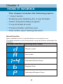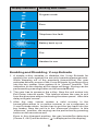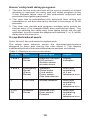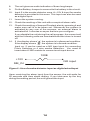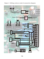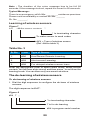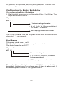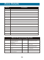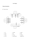
1
Getting
Started
Manual
and
Installation
Guide
V-Cop Entrada
Table of contents
User's guide
Chapter 1.Overview ..................................................................5
About V-cop Entrada ..................................................................5
Technical Specifications .............................................................6
Chapter 2.How it works ............................................................8
How it works ...............................................................................8
Enabling and disabling the V-cop Entrada..................................9
Users' entry/exit delay program ................................................10
V-cop Entrada at work .............................................................10
Communication with the user ...................................................11
User action upon hearing the alert ...........................................11
Installation and configuration guide
Chapter 3.Installing the V-cop Entrada ................................13
Pre-installation checklist ...........................................................13
Installing the V-cop Entrada .....................................................13
Chapter 4.Configuring the V-cop Entrada ..........................17
Configuration Mode ..................................................................17
Appendix .................................................................................23
Audio indications ......................................................................23
3
Chapter 1
OVERVIEW
This chapter includes the following topics:
! About V-cop Entrada
!Technical Specifications
About V-cop Entrada
V-cop Entrada is a security system for offices and homes. The Vcop Entrada works as a system that initiates emergency alarms
for the user in case of certain security breaches. The system can
be customized to suit your needs based on the location,
architectural layout, sensing needs etc.
The V-cop Entrada based security system mainly consists of the
following units:
! V-cop Entrada with a built-in Battery backup of 36
hours.(without any sensor connected)
! Various Sensors like Door Magnetic Sensor, PIR, Smoke
Detector, Gas Leak Detector, vibration sensor
! Siren with flasher
! Auto dialer
The V-cop Entrada consists of a 7-segment display situated on the
front panel that gives the visual indication of various activities that
are in progress. The communication between V-cop Entrada and
the receiving phone is established via a telephone line and the
mobile network. When Unit detects an emergency, it dials
predefined telephone numbers and sends pre-recorded alerts for
the person who is going to take an action against that emergency-
5
referred as user.
Technical Specifications
Power
Supply
1. 170VAC to 270VAC, 50 Hz. (SMPS
adapter, O/P 13.5V/1A
2. 12V /1.3AH. 30-36 hours battery backup
when new and fully charged.
Battery charging time : 6 to 7 hours.
Input
1. 4 Input Wired sensor. Ex. wired
magnetic sensor(2 Delayed and 2 Panic)
2. 8 Wireless sensors
3. 1 input for smoke detector.
4. Telephone Line.
5. e-Key for Enabling/Disabling or Arming/
Disarming
Operator
inputs
With the help of telephone handset for
programming the unit.
Indication
7 segment LED display indication for
various zones' status.
Audio Buzzer indication for various
status indications.
FLASHER CUM SIREN Output.
Power
Consumption
Less than 2W
Table 2 : Mechanical Dimensions
Size
(48x175x90) mm( H x W x D)
Weight
Less than 1kg.
Table 3 : Environment
Operating
Temperature
0 to 50° C
Humidity
5 to 95 % RH.
6
Figure 1 : System Diagram
Wireless
PIR
Siren
with
Flasher
Wireless
Smoke
Detector
Mobile
Voice
Telephone
PSTN
(Telephone)
Telephone
Line
CMS (Optional)
(Central Monitor
Station)
1. Remote
Monitoring
2. Remote
Configuration
Magnetic
Switch
Remote
Control
Pendant
Wireless
Magnetic
Switch
7
Chapter 2
HOW IT WORKS
This chapter includes the following topics:
! How it works
!Enabling and disabling the V-cop Entrada
!Users' entry/exit delay program
!V-cop Entrada at work
!Communication with the user
!User action upon hearing the alert
How it works
After installation the V-cop Entrada is now ready for use.
The table printed on the front panel- as given below, describes its
working.
Display indication
Working zone status
Disarm mode
Arm mode
Activated Wired Zones
Bypass Zone
Activated Wireless Zone
8
Display indication
Working zone status
Program mode
Error
Telephone line fault
Flashing
Battery back up on
Fire
Handset in use
Enabling and Disabling V-cop Entrada
1. A simple e-Key enables or disables the V-cop Entrada for
alerting the user against the security breaches/emergencies.
While stepping out of the premises (home/office) the user
activates security zones of the V-cop Entrada, by putting e-Key
into the key reader. Now system is in “Armed” position. The
indication on the display at this stage will be . Arming can be
performed by pressing button on the remote as well.
2. The user has to preserve the e-Key. Now the unit enters into
Exit Delay interval mode. This interval allows the user to exit
from the premises without activating the alarm panel. After this
delay unit gets 'armed'.
3. After the user /owner makes a valid re-entry in the
house/office-either in a routine manner or as a response to
V-cop Entrada alerts, he/she has to put the key back into the
key reader. Now the unit is in the 'disarmed' position. In this
'disarmed ' position, dis-arming can be performed by pressing
button on the remote as well.
Even in this disarmed position, the gas /smoke/fire detectors
(Zones 3, 4 & 5) will be active.( ' ' is displayed on the display)
9
Users' entry/exit delay program
1. The time for the entry and exit of the user is usually of a fixed
duration in seconds. An entry and exit delay program in the
V-cop Entrada takes care of this authorized entry/exit and
prevents it from getting activated.
2. The user has to indicate/set this entry/exit time during the
installation or set this interval by him/her in the range of 10-90
seconds.
3. The User can decide and program multiple entry points for
his/her entry. (For example-Main door and kitchen door). The
unit, by sensing the valid entry from these points will not get
activated. In such a case the display will indicate '1' or '2-'which
delay zone the user is in.
V-cop Entrada at work
Once 'Armed'- the unit starts its vigilant work.
The wired zone sensors sense the disturbance/intrusions
assigned to them and convey the user about it. The display
indicates the kind of intrusion/disturbance sensed, as follows.
Table 2 : Displays at various intrusions
Display
Zone
Sensor type
Output
1 and 2
Delay
Zones
Magnetic sensors
PIR sensors
Shutter sensor
at main doors
Display
indication
3 and 4
Emergency
Zones
(Panic
Zones)
Vibration
Glass brake
Cord switch
Panic switch
Gas leak ditector
Siren and
autodialing
of 5 set
telephone no.s
F
Fire Zone
Smoke detector
Siren and
autodialing
of 5 set
telephone no.s
P1 to
P8
Wireless
Zones
Wireless PIR,
Door sensor,
Pendant
Siren and
autodialing
of 5 set
telephone no.s
10
Communication with the user
! The unit has a facility to record the alert message in user's own
voice. It has 20 seconds of such message memory. The
message is played repetitively in two cycles (two times), at the
time of raising an alert.
! After the unit is activated it alerts the user in his/her own voice
on the telephone or the mobile once it receives the signals of
intrusion or trouble or emergency from the respective Sensors.
! The unit begins dialing another telephone number from the list
of five numbers, after the first dial is over. The telephone
numbers of the location 1 to 5 are dialed sequentially. The unit
gives such dialing alert to all the 5 numbers two times.
! During the call, an external siren is also turned on. The user
can program the siren play time from 1-9 minutes, in the
configuration mode.
! Further calls are terminated if the user intervenes with the key
and disarms the unit during the call.
The units with wireless sensors have a similar working of the 8 no.
of sensors P1 t o P8.
User action upon hearing the alert
The user gets the telephonic/siren alert and re enters the
premises. The user looks at the number displayed on the
unit/panel to know the nature of intrusion /trouble/emergency. The
number on the display, as described in table 2, helps the user in
identifying it.
The user puts the e-Key in its place on the panel, now
V-cop Entrada is 'disarmed'.
11
Chapter 3
INSTALLING THE
V-COP ENTRADA
This chapter includes the following topics:
!Pre-installation checklist
!Installing the V-cop Entrada
Pre-installation checklist
Before proceeding with the installation, it is recommended to
check the contents of your V-cop Entrada pack.
Ensure you have the following with you:
! V-cop Entrada
! Power supply adapter
! Battery - 12V/1.3 AH
! RJ -11-M/M-1 No.
! User manual
*Note :
Battery - 12V/1.3AH is supplied by the manufacturer(RASS)
along with the V-Cop Entrada Unit.
Installing the V-cop Entrada
1. Select a central location in your premise to install the
V-Cop Entrada.
2. Connect the telephone line to RJ 11 x INPUT connector no. 5.
3. Connect the telephone instrument to the RJ 11 x Output
connector no. 6.
4. Connect the wired sensors to the Connector.
Note : All Sensor inputs are Permanent NC type. The NC type
inputs reduce false alarms considerably..
5.
Ensure that the Mains Socket is OFF.
6.
Insert the SMPS Power Adapter from the to the Mains
socket.
7.
Connect the other end of the adapter to the unit and switch on
the mains (230 V Ac).
13
8.
The unit gives an audio indication of three long beeps.
9.
Put the Battery Jumper to connect to the battery in the circuit.
10. Input 5 is the smoke detector zone. A +12V & input for smoke
detector is provided in this zone. This input can also be used
as a digital input.
11. Leave the system running.
12. Check the working of the unit with a couple of alarm calls.
13. Check the working of learned Pendent also by pressing it and
make sure call is to be taken out. Whenever the system is
activated by any one of the sensors, an external alarm is
activated for 1 minutes or as per the time you configure.
If you disable the unit during the call progress, the current call
and the following calls are terminated and the siren is turned
off.
14. If the display shows ' ', the system is in disarmed condition.
If the display shows ' ', the system is in Armed condition.
Input no. 5 can be used as a NO type input for connecting
Panic Switches or 4 wire smoke detectors. You need to
insert about 120E resistor to connect such input device.
120E
+12V
NO input
SM_IN
Figure 2 : Use of smoke detector input as digital wired input
Upon receiving the alarm input from the sensor, the unit waits for
20 seconds and then starts dialing. If you intervene by the key
during the waiting period, the unit ignores the input.
14
Figure 3 : Wiring colours code & connection diagram
17 18
Black
Red
Adaptor Input
Buzzer ON/OFF
Battery ON/OFF
Line IN
Red
13
Blue
Red
15
14
Blue
Door
Magnetic
Sensor or
Shutter
Senser
16
White
1
White
2
3
Alarm - +
PIR
or
Beam
Detector
4
White
White
5
Blue
Red
Red
6
Smoke +
Detector -
Panic Switch
or
Cord Switch
7
Blue
White
NC
8
White
LPG
Detector
9
10
+
11
12
+
Red +
Blue -
Battery
Connector +
Hooter
15
Chapter 4
CONFIGURING THE
V-COP ENTRADA
This chapter includes the following topics:
! Configuration Mode
! Normal Mode
Configuration Mode
In the Configuration mode, you can configure the V-cop Entrada
for the following functions:
! Storing Five telephone numbers
! Message recording
! Setting Entry / Exit delay
! Setting Siren ON time
! Enabling or Disabling the Chime/Chirp mode
! Learning and de-learning of wireless sensors
Configuring the unit (Programming the unit)
You can configure the unit only when it is in the Disarmed
condition. The unit switches to the configuration (Programming)
mode when you press #123 on the telephone instrument.
To configure the unit
1. Lift the handset of the telephone instrument connected to
V-cop Entrada. Display shows ‘ ’.
2. Input #123 from the telephone. The unit enters the program
mode. Throughout this mode, an audio beep is heard
intermittently.
3. A pre-defined configuration ends the configuration mode, if the
time out occurs before finishing the configuration. The time out
period is 20 seconds.
4. The configuration exits the configuration mode, after you
receive the **. After receiving the second *, the data is updated
to the internal memory.
Note: Upon failure of the configuration, the unit gives a long beep
sound three times.
17
Configuring the Chime/Chirp Function
To activate/deactivate the Chirp Function
1. Dial the digit sequence to configure the chime / chirp on/off.
The digit sequence is #00X *
Figure 4
#00
X
*
* Is terminating character.
X = 0 or 1 ( 0:- OFF ; 1:- ON.)
#00 is program code number
Learning E-key with V-Cop Entrada 1. Dial the digit sequence to configure the learning of E-key. The
digit sequence is #916. Touch key *. ‘H’ will shown on display.
D-learning E-key with V-Cop Entrada 1. Dial the digit sequence to configure the d-learning of E-key.
The digit sequence is #917X. ‘ ’ will shown on display.
CHIME/CHIRP Function
In the Disable mode, if the wired zone 1 is triggered by opening
sensor contacts, the unit gives Chirp to indicate that the door is
being opened. This indication is called 'Chime/Chirp'.
Configuring the telephone numbers
To configure the telephone numbers
1. Dial the digit sequence for programming the telephone
numbers from the connected handset. The digit sequence is :
18
Figure 5
# 011 #
24339634
*
Last * digit is for
terminating character
Max 15 digit, in between # and
* is a Telephone Number.
# Is a separator.
One digit Telephone serial
number (1to 5).
First two digits are for Program
serial number. (#01 for
tel. Number programming)
Note: It is possible to connect the V-cop Entrada to the EPABX
extension. In such case # is used to insert a Pause between
storing of the numbers. e.g. if '0' is to be dialed to access the
telephone line, you should program as, #011#0#24339634*.
However we do not recommend connecting the unit to an EPABX
extension. If the EPABX telephone lines are busy, the unit will not
be able to dial any number in case of emergency.
Recording a message
To record a message
1. Dial the digit sequence to record a message. The digit
sequence is #02 < After a you hear a beep, start recording till a
long beep is heard > *
Figure 6
#02 <Message>
*
* Is terminating
Speak out your message to be recorded.
#02 is a Configuration (Program) serial
When the unit receives #02, a beep is heard on the telephone
instrument. You can record the message till the unit gives a long
beep sound after 20 seconds.
After 20 seconds it waits for a quitting character *.
You can confirm the recording by making a test call as standard
emergency call.
19
Note : The duration of the voice message has to be full 20
seconds. If the message is short, repeat it to cover for 20 seconds.
Typical Message :
There is an emergency at Mr./Ms. ________ residence premises.
Please rush immediately or contact Mr./Ms. ______
Ph. No. _______.
Learning of wireless sensors
Figure 7
#xx
<Make sensor contact>
*
* Is terminating character
To make sensor to send codes
#XX = Type of wireless sensor
(Ref. Above table 3)
Table No. 3
Sr No.
Code
Type of Sensor
1.
#06
Arm/Disarm Remote Learning.
2.
#03
Alert sensor Learning.
3.
#08
For delayed wireless sensor learn
Enter the appropriate code to select learn mode. Make sensor
contact (You will hear a bip sound) and then press * to exit from the
learning mode. You can learn only one sensor at a time.
The de-learning of wireless sensors
To de-learning of wireless sensors
1. Dial the digit sequence to configure the de-learn of wireless
sensors.
The digit sequence is #047*.
Figure 8
#04 7
*
* Is terminating character.
7 is for de-learning
#04 is program serial number
20
De-learning of individual sensors is not possible. The unit exits
the configuration mode when it receives *.
Configuring the Entry / Exit delay
To configure the Entry / Exit delay
1. Dial the digit sequence to configure the Entry / Exit Delay. The
digit sequence is #05X *
Figure 9
#05 X *
* Is terminating character.
X = 1 To 9 ( at 10Sec resolution.)
1=10Sec…9=90Sec.
#05 is program serial number
The V-cop Entrada exits the program mode after two successive
character ** are pressed.
Zone Bypass
To bypass wired zone 1 or 2.
Dial the digit sequence to bypass particular wired zone.
The digit sequence is #07X*.
Figure 10
#07 X *
* Is terminating character.
X =1,2 or 0 (1=zone1, 2=zone2,
0=bypass cancel)
#07 is program serial number
Example : If you dial digit sequence #071*, then zone 1 will be
bypassed. Similarly, you can bypass zone 2 also. At a time only 1
zone can bypass. Dial #070* for bypass cancel.
21
Telephone error
The Telephone error ' ' means that the telephone line is either
not present or is not connected properly.
The ' ' is displayed on the 7-segment display.
While enabling the unit if the doors are open then during enabling
period display shows input number in which doors are open. Unit
doesn't enable(sense) the particular input until all the doors
connected to it are closed.
Configuring the Siren ON time
To configure the Siren On time
1. Dial the digit sequence to configure the Siren on/off. The digit
sequence is #09X*.
Figure 11
#09 X *
* Is terminating character.
X = 1 or 9 (1 minute to 9 minutes)
#09 is program code number
22
APPENDIX
Audio indications
! Power ON: Buzzer beeps three times.
! Error in programming: Three long beeps.
! Success in programming: One short beeps.
! Program mode: Buzzer once.
! Any input alert: once.
! System arm: Buzzer beeps in regular interval. If all doors are
closed then buzzer gives beeps with long pause & if any one
door is opened then it gives beeps with a short pause.
23
Disclaimer
Realty Automation and Security Systems Private Limited, herein
after referred to as RASS warrants this unit to be free of defects in
materials and workmanship for a period of 13 months from date of
purchase. RASS's WARRANTY adds an additional one (1) month
grace period to the normal one (1) year product warranty to cover
handling and shipping time. This ensures that RASS's customers
receive maximum coverage on each product.
If the unit malfunctions, it must be returned to the dealer / factory
for evaluation. RASS's Customer Service Department will issue
an Authorized Return (AR) number immediately upon phone or
written request. Upon examination by RASS, if the unit is found to
be defective, it will be repaired or replaced at no charge. RASS's
WARRANTY does not apply to defects resulting from any action of
the purchaser, including but not limited to mishandling, improper
interfacing, operation outside of design limits, improper repair, or
unauthorized modification. This WARRANTY is VOID if the unit
shows evidence of having been tampered with or shows evidence
of having been damaged as a result of excessive corrosion; or
current, heat, moisture or vibration; improper specification;
misapplication; misuse or other operating conditions outside of
RASS's control.
Components, in which wear is not warranted, include but are not
limited to contact points, fuses, and triacs. RASS is pleased to
offer suggestions on the use of its various products. However,
RASS neither assumes responsibility for any omissions or errors
nor assumes liability for any damages that result from the use of its
products in accordance with information provided by RASS, either
verbal or written. RASS warrants only that the parts manufactured
by the company will be as specified and free of defects. RASS
MAKES NO OTHER WARRANTIES OR REPRESENTATIONS
OF ANY KIND WHATSOEVER, EXPRESSED OR IMPLIED,
EXCEPT THAT OF TITLE, AND ALL IMPLIED WARRANTIES
INCLUDING ANY WARRANTY OF MERCHANTABILITY AND
FITNESS FOR A PARTICULAR PURPOSE ARE HEREBY
DISCLAIMED. LIMITATION OF
LIABILITY: The remedies of purchaser set forth herein are
exclusive, and the total liability of RASS with respect to this order,
whether based on contract, warranty, negligence, indemnification,
strict liability or otherwise, shall not exceed the purchase price of
the component upon which liability is based. In no event shall
RASS be liable for consequential, incidental or special damages.
CONDITIONS: Equipment sold by RASS is not intended to be
used, nor shall it be used: (1) with any nuclear installation or
activity; or (2) in medical applications or used on humans. Should
any Product(s) be used in or with any nuclear installation or
activity, medical application, used on humans, or misused in any
way, RASS assumes no responsibility as set forth in our basic
WARRANTY/DISCLAIMER language, and, additionally,
purchaser will indemnify RASS and hold RASS harmless from any
24
liability or damage whatsoever arising out of the use of the
Product(s) in such a manner.
RETURN REQUESTS/INQUIRIES
Direct all warranty and repair requests/inquiries to the RASS
Customer Service Department. BEFORE RETURNING ANY
PRODUCT(S) TO RASS, PURCHASER MUST OBTAIN AN
AUTHORIZED RETURN (AR) NUMBER FROM RASS'S
CUSTOMER SERVICE DEPARTMENT (IN ORDER TO AVOID
PROCESSING DELAYS).
The assigned AR number should then be marked on the outside of
the return package and on any correspondence. The purchaser is
responsible for shipping charges, freight, insurance and proper
packaging to prevent breakage in transit.
FOR WARRANTY RETURNS, please have the following
information available BEFORE contacting RASS:
1. Purchase Order number, under which the product was
PURCHASED,
2. Dealer code, Model and serial number of the product under
warranty, and
3. Repair instructions and/or specific problems relative to the
product.
FOR NON-WARRANTY REPAIRS, consult RASS for current
repair charges. Have the following information available BEFORE
contacting RASS:
1. Purchase Order number to cover the COST of the repair,
2. Dealer code, Model and serial number of the product, and
3. Repair instructions and/or specific problems relative to the
product.
RASS's policy is to make running changes, not model changes,
whenever an improvement is possible. This affords our customers
the latest in technology and engineering.
RASS is a registered trademark of Realty Automation & Security
Systems Pvt. Ltd.
© Copyright 2009 RASS. All rights reserved. This document may
not be copied, photocopied, reproduced, translated, or reduced to
any electronic medium or machine-readable form, in whole or in
part, without the prior written consent of Realty Automation
Security System Pvt. Ltd.
25
Zone Details
Zone
Location
Quick Programming Guide
Program Code
Program Code
Description
Description
Chime Chirp Activation
Deactivation #001 For
Activation & #000 For
Deactivation
Configuring Telephone
numbers 1 to 5
#06
To learn Wireless Remote
to Arm/Disarm the system
#07
To Bypass wired input
Zone 1 OR 2
#02
Message recording
#08
To learn Arm/Disarm Type OR
Delayed wireless sensor
#03
To learn Alert wireless
sensor
#09
Configuring Siren ON time
1 to 9 Minutes
#047
To Delearn Alert wireless sensor
#916
Configuring E-Key to the system
#05
Configuring Entry/Exit Delay
10 to 90 seconds
#917
Deconfiguring E-Key
#00
#01
26
V-Cop Entrada Warranty
(Customer Copy) Sr. No. ____________
W e h e r e b y e x t e n d w a r r a n t y f o r V- C o p E n t r a d a
for a period of 12 calendar months from the date of purchase
to the original purchaser against any defects in materials and
workmanship, In case of any defects we undertake to
repair the same free of charge, as per the terms of warranty.
This warranty will be void if the defect arises due to
mishandling or tampering of the product. The warranty is
limited to the extent of replacement of the product. We are in
no way liable for any other loss or claims.
Name:
Address:
Tel.:
Bill No.:
Warranty valid upto:
E-mail:
Dt. of purchase:
Dealer's Sign & Rubber Stamp
Realty Automation & Security Systems Pvt. Ltd
5, New Sadashiv Peth, Near Alka Talkies,
Pune - 411 030. Maharashtra, India
(Company Copy) Sr. No. ____________
W e h e r e b y e x t e n d w a r r a n t y f o r V- C o p E n t r a d a
for a period of 12 calendar months from the date of purchase
to the original purchaser against any defects in materials and
workmanship, In case of any defects we undertake to
repair the same free of charge, as per the terms of warranty.
This warranty will be void if the defect arises due to
mishandling or tampering of the product. The warranty is
limited to the extent of replacement of the product. We are in
no way liable for any other loss or claims.
Name:
Address:
Tel.:
Bill No.:
Warranty valid upto:
E-mail:
Dt. of purchase:
Dealer's Sign & Rubber Stamp
Realty Automation & Security Systems Pvt. Ltd
5, New Sadashiv Peth, Near Alka Talkies,
Pune - 411 030. Maharashtra, India
27
Realty Automation &
Security Systems Pvt. Ltd.
5 New Sadashiv Peth, Pune-411030, INDIA.
Tel
: +91 20 3292 1306; 3292 2630.
Telfax : +91 20 2433 9628
Email : [email protected]
Web : http://www.vighnaharta.in