1
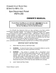
EmerGen Switch®
Manual Transfer Switch
OWNER’S MANUAL AND
INSTALLATION INSTRUCTIONS
For “A” Series Models 6-5001, 6-7501, 10-7501, 10-12K1
PLEASE READ THIS MANUAL IN ITS ENTIRETY
BEFORE INSTALLING AND/OR OPERATING YOUR
EmerGen Switch®
RETAIN THIS MANUAL FOR FUTURE REFERENCE
Congratulations on the purchase of your new
EmerGen Switch®®
Corporate Office: 5508 - 128th St. E, Puyallup, WA 98373, Ph. 1(800) 472-3819, Fax (253) 471-9540
Sales / Engineering: 425 Sycamore St., Anderson, IN 46016 Ph. 1(800) 730-2557, Fax (765) 608-5036
Your new EmerGen Switch will provide you with a way to safely utilize
your generator power through your existing electrical wiring during a power
outage. You’ll install your switch next to your home’s electrical panel load
center and then you’ll connect circuit breaker wires to the transfer switch’s
circuits. Once you power up your portable generator, you will manually turn on
each switch and that generator energy is transferred as electrical power and
goes through the house circuits you have previously chosen.
Your EmerGen Switch is easy for a licensed electrician or qualified
professional to install, safe for a homeowner to operate, and will work with
120/240V single phase AC generators, factory equipped with NEMA type
receptacles L14-20R, L14-30R or 3 pole, 4 wire California Standard 50 amp
twist-lock receptacle, depending on the size EmerGen Switch you have chosen.
Your EmerGen Switch will not permit connection to both utility and generator
power at the same time.
Table of Contents
Product Outline
Page 3
Safety Information
Installation Preparation
Page 4
Wattage Requirements
Page 5
Installation Instructions
Page 6
Wiring to the Load Center
Page 7
Installing 240 volt (2 pole) Circuits
Page 8
Completing the Installation
Page 9
Operation / Test Procedure
Load Management
Page 10
Trouble Shooting
Page 11
Product Warranty
Page 12
2
Warning:
Improper installation of this transfer switch could cause
damage or personal injury by electrocution or fire.
Installation must be performed by a licensed electrician
or qualified professional in accordance with applicable
electrical codes.
Specifications
Model
Maximum Watts
Number (including surges)
6-5001
6-7501
10-7501
10-12K1
5000 watts
7500 watts
7500 watts
12000 watts
Maximum
Combined
Loads at
250VAC
Number of Number
Total
15 amp of 20 amp
Circuits
circuits
circuits
20 Amps
30 Amps
30 Amps
50 Amps
6
6
10
10
Powder coated steel
enclosure will not rust.
4
4
6
6
2
2
4
4
Power
Inlet
L14-20
L14-30
L14-30
CS6375
Side installation bars
allow easy surface
mount installation.
Push-to-reset
circuit breakers
Built-in watt meters
Double throw switches
prevent power back feed.
Locking power inlet
3
SAFETY INFORMATION
1. The National Electrical Code states the connection of a generator to any
electrical circuit normally powered by an electrical utility, must be by means
of an approved transfer switch so as to isolate the electrical circuit from the
utility system when the generator is operating. Your EmerGen Switch is
approved by a Nationally Recognized Testing Laboratory to accomplish the
isolation this code is requiring.
2. Your EmerGen Switch is for indoor use only.
3. A licensed electrician or qualified professional must install this EmerGen
Switch according to local code.
4. To reduce the risk of electrical shock, the MAIN circuit breaker in the load
center must be in the OFF position during the course of installation.
GENERATOR
1. The portable generator used with your EmerGen Switch, must be operated
outside of any building.
2. Always plug the power cord set into your generator and into the EmerGen
Switch before starting the generator and always shut the generator down
before detaching the power cord set.
3. Do not overload your generator or its circuit breakers will trip. Using the
EmerGen Switch’s built-in watt meters, you can balance the loads to avoid
impeding your generator’s performance.
INSTALLATION PREPARATION
1. Decide which circuits will be powered by the generator during a power
outage. The recommended circuits include the fireplace fan or furnace fan
(gas or fuel only), sump pump, refrigerator, freezer, one lighting or kitchen
appliance circuit, and perhaps one lighting circuit elsewhere. Most well
pumps are 240V—or any other 240V appliance—will utilize two EmerGen
Switch circuits. (C&D on the 6 circuit models or D&I or E&J on the 10 circuit
models).
2. Identify the load center circuits you’ve determined are less than 15 amps.
Designate each EmerGen Switch circuit that will be used. Identify the load
center circuits that are greater that 15 amps. Designate these circuits for use
on the 20 amp EmerGen Switch circuits.
Note: If a circuit you have selected is a GFCI circuit breaker, it
will not be a GFCI circuit while it is powered by the generator/
4
Running
Appliance
Wattage
Furnace Fan (gas or fuel)
1/8 Horsepower
300
1/6 Horsepower
500
1/4 Horsepower
600
1/3 Horsepower
700
1/2 Horsepower
875
Well Pump
1/3 Horsepower
750
1/2 Horsepower
1000
Sump Pump
1/3 Horsepower
800
1/2 Horsepower
1050
Light Bulbs (incandescent) as marked
Refridgerator or Freezer
700
Garage Door Opener
1/4 Horsepower
550
1/3 Horsepower
725
Microwave Oven (600 watt)
600
Television
300
Coffe Maker (typical)
1750
Dehumidifier
650
Portable Heater
1000 - 1500
Water Heater
3500
Start-Up
Wattage
500
750
1000
1400
2350
Typical installation
1400
2100
1300
2150
0
2200
1100
1400
800
0
0
800
0
0
WATTAGE REQUIREMENTS
1. Most appliances and motors have current ratings noted directly on the units.
Light bulb wattages are noted on the bulb
2. Some electrical motors surge in power when first started. Your EmerGen
Switch has watt meters so you can monitor the flow of these start-up surges
without impeding your generator’s performance.
3. Load balance is obtained by the pre-determination of chosen circuits. Try to
distribute loads with similar wattage requirements equally on the left and
right sides of the EmerGen Switch. Example; place the refrigerator on circuit
A and the freezer on circuit F on the 6 circuit models.
5
INSTALLATION INSTRUCTIONS
1. Determine where you want
your EmerGen Switch located,
either to the left or right of the
load center. The switch should
be approximately 18” from the
center of the load center,
making sure that there is plenty
of room to properly connect the
flex conduit whip.
2. TURN OFF POWER. The main circuit breaker in your load center should be
switched to the OFF position. CAUTION—this does not affect the wires on the
line side of the main breaker—they will remain live! Remove the cover of the load
center.
3. Identify the appropriate knockout to
remove. 3/4” for the 6 circuit models, 1” for
the 10-7501 and 1-1/4” for 10-12K1 model.
4. Insert the wires from the flex
conduit up through the
knockout; take care not to nick
or gouge the wires on the metal
edge. Tighten the locknut
securely onto the load center.
The wires can hang freely.
5. Without over-manipulating the flex conduit, secure your EmerGen Switch to the
wall with fasteners appropriate for the wall’s construction. If you are mounting
this unit flush to the wall, follow instructions included with the Flush Cover Kit.
6
Wiring the EmerGen Switch to the Load Center
1.
From your plan, locate the circuit breaker that is to be connected to the
EmerGen Switch circuit “A”. Turn that circuit breaker to the OFF position. Loosen
the lug securing the wire and remove the wire.
WARNING: Transfer switch circuits with 20 amp breakers must be installed to
circuits with 20 amp branch circuit breakers in your load center. Transfer switch
circuits with 15 amp breakers can be installed on 15 or 20 amp branch circuits.
Do not install any transfer switch circuit on branch circuits greater than 20
amps.
2.
Find both the red and black EmerGen Switch wires labeled “A”. Using good
workmanship, route both of these wires close to the selected circuit breaker.
a) The red EmerGen Switch “A” wire is
trimmed, stripped and installed into
the circuit breaker, securely
tightening the breaker lug.
b) The black EmerGen Switch “A” wire
and the hot wire from the circuit
breaker (removed in step 1) are
placed up the side of the load
center together.
c) After removing 5/8” of the insulation
from the black EmerGen Switch “A”
wire, insert both wires into a yellow
wire connector. Twist the
connector tightly and push the
wires back into the wiring
compartment of the load center.
3.
Repeat step 2 for each 120
volt circuit. See the following section
for the installation of 240 volt
circuits.
7
Installing 240 Volt (2 pole) Circuits
EmerGen Switch products provide circuits for the connection of 240 volt
appliances that are connected to 2 pole branch circuit breakers in your load
center. These EmerGen Switch circuits for 240 volt operation have a handle tie
installed that ties two circuit selector switches together in the following
positions:
Models 6-5001 & 6-7501 Circuits C & D
Models 10-7501 & 10-12K Circuits D & I, Circuits E & J
If you do not wish to use the designated circuits as 2 pole circuits, simply
remove the handle tie by removing the two screws.
For the purpose of this example, circuits C & D of model 6-5001 will be used.
a) The red EmerGen Switch “C” wire is trimmed, stripped and securely installed
into one side of the 2 pole circuit breaker.
b) The black EmerGen Switch “C” wire and one of the hot wires from the circuit
breaker are placed up the side of the load center. Insert both wires into a
yellow wire connector and twist tightly. Push the wires back into the wiring
compartment of the load center.
c) The red EmerGen Switch “D” wire is trimmed, stripped and securely installed
into the remaining side of the 2 pole circuit breaker.
d) The black EmerGen Switch “D” wire and the remaining hot wire from the
circuit breaker are placed up the side of the load center. Insert both wires
into a yellow wire connector and twist tightly. Push the wires back into the
wiring compartment of the load center.
Note: For this example, a 125 amp panel is used for illustration purpose only
8
Completing the Installation
1) When the preceding steps have been completed for all desired circuits, the
EmerGen Switch white (neutral) wire(s) needs to be installed.
a.
Select any unused hole on the neutral bar in the load center.
b.
Cut and strip the wire appropriately. Insert the wire into the hole
and tighten securely.
2) The EmerGen Switch green (ground) wire(s) needs to be installed into an
unused hole in the ground bar in the load center.
a.
Select an unused hole in the ground bar in the load center.
b.
Cut and strip the wire appropriately. Insert the wire into the hole
and tighten securely.
3) Replace the load center cover. All circuit breakers can now be turned on
including the MAIN circuit breaker.
4) All EmerGen switches should be in the “Line” position. The “Off” position is
generally not used.
5) Fill out the chart supplied with your EmerGen Switch describing each
emergency circuit and corresponding circuit breaker. Please this label on or
near your EmerGen Switch for easy reference.
EmerGen Switch
EGS
Circuit
Circuit No.
at Load Center
Circuit
Description
A
8A
Freezer
B
5B
Rec Room Lights
C
2A
Barn Pump
D
3A
E
4B
Lights
F
10B
Furnace Fan
9
Operation / Test Procedure
1. Switch positions should remain in the “LINE” position under normal utility
power. The “OFF” position is generally not used. The “GEN” positions are used
when connecting circuits to your generator power source.
2. When testing and/or switching to generator power after a power outage,
ensure all switches are in the “LINE” position. (There is no need to turn off
any load center circuit breakers).
3. Plug your power cord set into your generator by aligning the male prongs with
the female terminals of your generator’s receptacle, push the connector in
and twist clockwise to lock (some connectors do not twist). Align the female
socket of the cord set into your EmerGen Switch, push it in and turn
clockwise to lock.
4. Move your generator outdoors before starting it up. Check to see that fluids
and fuel are adequate and start your generator according to the
manufacturer’s instructions.
5. At your EmerGen Switch, move one circuit to the “GEN” position, making a
note of how much wattage is used on the watt meter. While monitoring the
load, flip each circuit—one at a time—to the “GEN” position. You do not need
to go “in order” and you want to balance the loads so that both meters read
approximately the same. Do not switch on more loads than your generator
can supply.
Note: Wattage must not exceed the maximum printed on the meters.
Load Management
1. All circuits can be used simultaneously only if your generator has sufficient
wattage capacity. If an electrical load on the EmerGen Switch is exceeded by
it’s capacity, the mini-breaker may trip.
To Reset:
a.
Eliminate the overload condition.
b.
Move the switch with the tripped breaker to the “OFF” position.
c.
Reset the breaker by pressing it in, making sure it stays in.
d.
Move the switch back to the “GEN” position. It should now operate
properly. If it does not, you may need to contact an electrician or
qualified professional.
10
Trouble Shooting
Problem
Generator is running
Cause
1. Generator circuit breaker
but no AC output is
has tripped.
Solution
1. Reset circuit breaker.
available.
2. Poor connection or
2. Check and repair.
defective cord set.
3. Connected device is bad.
3. Select a different load or
appliance that is in good
4. Fault in generator.
condition.
4. Contact a qualified
professional.
Generator runs good
1. Short circuit in a
1. Disconnect shorted electrical
but bogs down when
connected load.
load.
2. Generator is overloaded.
2. Review load power
loads are connected.
requirements and rearrange.
Switches are not
1. Switches are in OFF or LINE 1. Move switches to GEN
working with
position.
position.
2. Generator circuit breaker
2. Reset circuit breaker.
generator power.
has tripped.
3. Poor connection or
3. Check and repair.
defective cord set.
4. Connected device is bad.
4. Select a different load or
appliance that is in good
condition.
5. Fault in generator.
5. Contact a qualified
professional.
Appliances do not
1. Switches are in GEN or OFF 1. Move switches to LINE
operate after utility
position.
position.
2. Circuit breaker tripped.
2. Reset circuit breaker.
1. Circuit breaker tripped.
1. Reset circuit breaker.
2. Poor connection or
2. Check and repair.
power is restored.
Only some loads
work on generator
power.
defective cord set.
GFCI breaker on
1. Neutral / Ground bond in
1. Contact Honda dealer for
Honda generator
generator
alteration.
trips when
connected to switch
11
Product Warranty
Every EmerGen Switch is guaranteed against mechanical or electrical failure due to
manufacturing defects for a period of one year from the date of purchase.
Connecticut Electric warrants to the purchaser that this product will be free from defects
in material and workmanship and will be of the kind and quality designated. This
warranty shall apply only to defects appearing within one year of the original date of
purchase.
The liability of Connecticut Electric under this warranty, or for any loss or damage to the
equipment shall not in any case exceed the cost of correcting defects in the equipment
and upon the expiration of the warranty period, all such liability shall terminate.
Connecticut Electric warrants that at the time of purchase, the products manufactured
and sold shall be in conformity with applicable written specifications, free from defects in
material and workmanship, merchantable, and suitable for a particular purpose, provided
such is implied by state law under the circumstances of this sale.
•
Connecticut Electric agrees to repair or furnish a replacement for, but not remove or
install, any product or component thereof which, within one year from the original
date of purchase upon test or examination by Connecticut Electric, prove to be
defective within the above warranty.
•
Buyer shall notify Connecticut Electric of any defect within this warranty no later
than thirty (30) days after a defect is discovered.
•
No product shall be accepted for return or replacement without authorization from
Connecticut Electric. Contact Connecticut Electric Corporate Office to obtain a
Return Goods Authorization Number. Proof of Purchase will be required to verify
the original purchase date.
This warranty is limited solely to the above and applies only for the period set forth.
Connecticut Electric will not be liable for any loss, damage, incidental or consequential
damage of any kind, whether based upon warranty contact, or negligence, and/or arising
in connection with the sale, use, installation or repair of this product. Connecticut
Electric’s maximum liability shall not, in any case, exceed the contract price for the
products claimed to be defective or unsuitable.
This warranty does not extend to any product manufactured by Connecticut Electric
which has been subjected to misuse, neglect, accident, improper installation or use in
violation of instructions furnished.
This warranty does not extend to or apply to any unit which has been repaired or altered,
either to the product or to the components manufactured by any other supplier other
than Connecticut Electric.
12