1
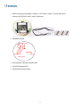
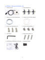
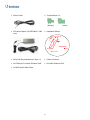
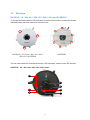
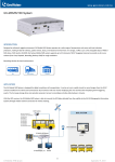
Quick Start Guide GV-Fisheye IP Camera Thank you for purchasing GV-Fisheye IP Camera. This guide is designed to assist the new user in getting immediate results from the GV-Fisheye IP Camera. For advanced information on how to use the GV-Fisheye IP Camera, please refer to GV-Fisheye IP Camera User's Manual on Software DVD. © 2014 GeoVision Inc. All rights reserved. FE-QG-G © 2014 GeoVision, Inc. All rights reserved. Under the copyright laws, this manual may not be copied, in whole or in part, without the written consent of GeoVision. Every effort has been made to ensure that the information in this manual is accurate. GeoVision, Inc. makes no expressed or implied warranty of any kind and assumes no responsibility for errors or omissions. No liability is assumed for incidental or consequential damages arising from the use of the information or products contained herein. Features and specifications are subject to change without notice. Note: 1. GV-FE110 / FE420 / FE520 are excluded from Japan, EU and German market. 2. No memory card slot or local storage function for Argentina. GeoVision, Inc. 9F, No. 246, Sec. 1, Neihu Rd., Neihu District, Taipei, Taiwan Tel: +886-2-8797-8377 Fax: +886-2-8797-8335 http://www.geovision.com.tw Trademarks used in this manual: GeoVision, the GeoVision logo and GV series products are trademarks of GeoVision, Inc. Windows and Windows XP are registered trademarks of Microsoft Corporation. June 2014 Contents Naming and Definition ..........................................................................iii Note for Connecting to GV-System .....................................................iv Note for Recording.................................................................................v Note for USB Storage and WiFi Adapter .............................................vi Note for Installing Camera Outdoor ...................................................vii Optional Accessories............................................................................ix 1. 2. 3. Introduction......................................................................................1 1.1 Packing List ..............................................................................................................2 1.2 Overview...................................................................................................................7 Installation......................................................................................11 2.1 Hard Ceiling Mount.................................................................................................11 2.2 In-Ceiling Mount .....................................................................................................15 2.3 Wall Mount and Ground Mount...............................................................................18 Connecting the Camera ................................................................19 3.1 GV-FE110 / 111 / 2301 / 420 / 421 / 4301 / 520 / 521............................................19 3.2 GV-FER521 ............................................................................................................21 3.3 GV-FE2302 / 2303 / 3402 / 3403 / 4302 / 4303 / 5302 / 5303................................22 3.4 Connecting PoE Converter and IR LED Ring for GV-FE2303 / 3403 / 4303 / 5303... ...............................................................................................................................23 3.5 4. GV-FER3402 / 3403 / 5302 / 5303 .........................................................................25 Accessing the GV-Fisheye Camera .............................................28 4.1 Web Browser ..........................................................................................................28 4.2 Looking Up the Dynamic IP Address......................................................................29 4.3 Configuring the IP Address.....................................................................................31 4.4 Configuring the Wireless Connection .....................................................................33 i 5. The Web Interface..........................................................................36 5.1 Fisheye View ..........................................................................................................38 6. Upgrading System Firmware ........................................................41 7. Restoring to Factory Default ........................................................42 7.1 Using the Web Interface .........................................................................................42 7.2 Directly on the Camera...........................................................................................43 ii Naming and Definition GV-System GeoVision Analog and Digital Video Recording Software. The GV-System also refers to Multicam System, GV-NVR System, GV-Hybrid DVR System and GV-DVR System at the same time. iii Note for Connecting to GV-System The GV-Fisheye IP Camera is designed to work with GV-System, a hybrid or digital video management system. Note the following when the camera is connected to GV-System: 1. By default, the images are recorded to the memory card inserted in the GV-Fisheye IP Camera. 2. Once the camera is connected to the GV-System, the resolution set on the GV-System will override the resolution set on the camera’s Web interface. You can only change the resolution settings through the Web interface when the connection to the GV-System is interrupted. iv Note for Recording 1. By default, the images are recorded to the memory card inserted in the GV-Fisheye IP Camera. Make sure the Write recording data into local storage option is enabled. If this option is disabled, the camera will stop recording to the memory card while the live view is accessed through Web browsers or other applications. For details, see Video Settings, Administrator Chapter, GV-Fisheye IP Camera User’s Manual on the Software DVD. 2. Mind the following when using an inserted memory card for recording: Recorded data on the memory card can be damaged or lost if the data are accessed while the camera is under physical shock, power interruption, memory card detachment or when the memory card reaches the end of its lifespan. No guarantee is provided for such causes. To avoid power outage, it is highly suggested to apply a battery backup (UPS). For better performance, it is highly suggested to use Micro SD card of MLC NAND flash, Class 10. Replace the memory card when its read/write speed is lower than 6 MB/s or when the memory card is frequently undetected by the camera. v Note for USB Storage and WiFi Adapter Mind the following limitations and requirements for using USB storage and GV-WiFi Adapter: 1. The USB hard drive must be of 2.5’’ or 3.5’’, version 2.0 or above. 2. The USB hard drive’s storage capacity must not exceed 2TB. 3. USB flash drives and USB hubs are not supported. 4. External power supply is required for the USB hard drive. 5. To connect a GV-WiFi Adapter, make sure it is connected before the camera is powered on. vi Note for Installing Camera Outdoor When installing GV-FER outdoor models, be sure that: 1. The camera is set up above the junction box to prevent water from entering the camera along the cables. 2. Any PoE, power, audio and I/O cables are waterproofed using waterproof silicon rubber or the like. 3. The screws are tightened and the cover is in place after opening the camera cover. vii 4. An operating IR LED ring may reach high temperatures of up to 60°C (140°F). Disconnect the power supply and allow the IR LED ring to cool down before handling the device. IR LED Ring 5. The silica gel bag loses it effectiveness when the dry camera is opened. To prevent the lens from fogging up, use the supplied adhesive tap and replace the silica gel bag every time you open the camera, and conceal the gel bag in camera within 2 minutes of exposing to open air. 6. For each newly replaced silica gel bag, allow it to absorb moisture for at least 5 hours before operating the camera. viii Optional Accessories Optional devices can expand the capabilities and versatility of your GV-Fisheye Camera. Contact your dealer for more information. Name Details GV-PA191 The GV-PA191 is a Power over Ethernet (PoE) adapter Power over Ethernet (PoE) designed to provide power to the IP device through a single Adapter Ethernet cable. GV-Mount Accessories The GV-Mount Accessories provides a comprehensive lineup of accessories for installation on ceiling, wall and pole. For details, see GV-Mount Accessories Installation Guide on the software DVD. GV-WiFi Adapter The GV-WiFi Adapter is a plug-and-play device that provides WiFi connectivity to GV-IP Cameras through a mini USB port. This product complies with IEEE 802.11 b/g/n (Draft 3.0) standards for wireless networking. GV-POE Switch The GV-POE Switch is designed to provide power along with network connection for IP devices. The GV-POE Switch is available in various models with different numbers and types of ports. Power Adapter for GV-IR The power adapter is available in 6 regions: Argentina, LED Ring Australia, Brazil, Europe, U.K and U.S. Power Adapter for The power adapter is available in 6 regions: Argentina, GV-Fisheye Camera Australia, Brazil, Europe, U.K and U.S. ix 1. Introduction Welcome to the GV-Fisheye IP Camera Quick Start Guide. In the following sections, you will learn the basic installations and configurations of the GV-Fisheye IP Cameras listed below. For a detailed user manual, see the GV-Fisheye IP Camera User’s Manual on the GV-Fisheye IP Camera Software DVD. Note: Only GV-FER3402 / 3403 / 521 / 5302 / 5303 are for outdoor use. 1 1.1 Packing List GV-FE110 / 111 / 420 / 421 / 520 / 521 / 2301 / 4301 and GV-FER521 Fisheye Camera Support Bracket x 3 Camera Cover (Hard Ceiling Mount) Camera Cover (In-Ceiling Mount) Screw (Hard Ceiling Mount) x 3 Screw (In-Ceiling Mount) x 3 Torx Wrench Plastic Screw Anchor x 3 Installation Sticker GV-Fisheye IP Camera Software DVD GV-NVR Software DVD GV-NVR Quick Start Guide For GV-FE110 / 111 / 420 / 421 / 520 / 521 / 2301 / 4301 only: - 3-Pin or 2-Pin Terminal Block - DC 12V Power Adapter For GV-FER521 only: - Cable Connector - Silica Gel Bag and Adhesive Tape x 2 2 GV-FE2302 / 3402 / 4302 / 5302 and GV-FE2303 / 3403 / 4303 / 5303 Fisheye Camera Support Bracket x 3 Camera Cover (Hard Ceiling Mount) Camera Cover (In-Ceiling Mount) Screw (Hard Ceiling Mount) x 3 Screw (In-Ceiling Mount) x 3 Torx Wrench Plastic Screw Anchor x 3 Mini USB Extension Cable IR LED Ring (GV-FE2303 / 3403 / 4303 / 5303 only) 3 PoE Converter set (including 1 module, 1 DC Power Y-cable, 1 RJ-45 cable and 3 screws) (GV-FE2303 / 3403 / 4303 / 5303 only) Installation Sticker GV-Fisheye IP Camera Software DVD GV-NVR Software DVD GV-NVR Quick Start Guide 4 GV-FER3402 / 5302 and GV-FER3403 / 5303 Fisheye Camera Support Bracket x 3 Camera Cover (Hard Ceiling Mount) Camera Cover (In-Ceiling Mount) Screw (Hard Ceiling Mount) x 3 Screw (In-Ceiling Mount) x 3 Torx Wrench Plastic Screw Anchor x 3 IR LED Ring (GV-FER3403 / 5303 only) Waterproof Rubber 5 Power Cable Terminal Block x 2 (female) IR Power Adapter (GV-FER3403 / 5303 (male) Installation Sticker only) Silica Gel Bag and Adhesive Tape x 2 Cable Connector GV-Fisheye IP Camera Software DVD GV-NVR Software DVD GV-NVR Quick Start Guide 6 1.2 Overview GV-FE110 / 111 / 420 / 421 / 520 / 521 / 2301 / 4301 and GV-FER521 To access the Default button, LED indicators and micro SD card slot, unscrew the screws indicated below and then remove the camera cover. GV-FE110 / 111 / 2301 / 420 / 421 / 4301 / GV-FER521 520 / 521. GV-FER521 You can now access the Load Default button, LED indicators, and the micro SD card slot. GV-FE110 / 111 / 420 / 421 / 520 / 521 / 2301 / 4301: 5 6 1 2 7 3 8 4 7 GV-FER521: 1 2 3 6 5 7 8 4 No. Name Function 1 Lens Receives image inputs. 2 Speaker Talks to the surveillance area from the local computer. 3 Microphone Receives the sound from the camera. 4 Default Button Resets all configurations to default factory settings. See 7. Restoring to Factory Default in the Quick Start Guide. 5 Micro SD Card Slot Inserts a micro SD / SDHC memory card to store recorded data. 6 Network status LED Indicates the network status. 7 Power status LED Indicates whether the camera is powered on or off. 8 System status LED Indicates whether the system is booted successfully or not. Note: SDXC and UHS-I card types are not supported. 8 GV-FE2302 / 2303 / 3402 / 3403 / 4302 / 4303 / 5302 / 5303 1 2 3 No. Name Function 1. Lens Receives image inputs. 2. Speaker Talks to the surveillance area from the local computer. 3. Microphone Receives the sound from the camera. 4. Status LED Indicates whether the device is booted successfully or not. 5. LAN / PoE Connects to a 10/100 Ethernet or PoE. 6. Terminal Block Connects to power. 7. Default Button Resets all configurations to default factory settings. See 7. Restoring to Factory Default in the Quick Start Guide. 8. Audio Out Connects to an external speaker for broadcast. 9. Micro SD Card Slot Inserts a micro SD / SDHC memory card to store recorded data. 10. Mini USB Slot Connects to a GV-WiFi Adapter or a USB hard drive for external storage. Note: SDXC and UHS-I card types are not supported. 9 GV-FER3402 / 3403 / 5302 / 5303 1 2 3 No. Name Function 1. Lens Receives image inputs. 2. Speaker Talks to the surveillance area from the local computer. 3. Microphone Receives the sound from the camera. 4. LEDs See the LED Indicators section below for details. 5. Default Button Resets all configurations to default factory settings. See 7. Restoring to Factory Default in the Quick Start Guide. 6. Micro SD Card Slot Inserts a micro SD / SDHC memory card to store recorded data. 7. Terminal Block Connects to power. Note: SDXC and UHS-I card types are not supported. LED Indicators No. Name Function 1. Link Turns on when network is connected. 2. ACT Turns on when data are being transmitted or received. 3. Status Turns on when the device is ready. 10 2. Installation 2.1 Hard Ceiling Mount Without IR LED Ring With IR LED Ring Note: To connect wires, cables and the IR LED ring, see 3. Connecting the Camera in the Quick Start Guide. 1. Place the installation sticker on the ceiling board. The 3 red dots indicate the location of the screws. To install GV-Fisheye Camera with PoE converter (GV-FE2303 / 3403 / 4303 / 5303), drill the 3 holes and the rectangle block indicated as “PoE Converter”; to install GV-Fisheye Camera only with the IR LED ring (GV-FE2303 / 3403 / 4303 / 5303 and GV-FER3403 / 5303), drill the 3 holes indicated as “Device” and the circle indicated as “IR”. 2. At the 3 red dots, drill a hole slightly smaller than the plastic screw anchors provided. 11 3. Insert the 3 plastic screw anchors in the drilled holes. 4. For models other than GV-FE2303 / 3403 / 4303 / 5303, secure the fisheye camera with the 3 hard ceiling mount screws provided. 5. For outdoor GV-Fisheye Cameras (GV-FER3402 / 3403 / 521 / 5302 / 5303), install the supplied cable connector to waterproof the cable. You should have 5 components: 1 2 3 4 5 A. Prepare an internet cable with the RJ-45 connector on one end only. B. Connect the internet cable to the camera cable. C. Paste the installation sticker to the camera cable and slide in all the components as shown below. 12 D. Move all the components toward the RJ-45 connector, fit item 4 to item 2, secure item 3 to the camera cable and finally secure item 5 to item 2 tightly. IMPORTANT: Item 5 must be secured tightly to waterproof the cable. 6. For GV-Fisheye Camera that does not come with an IR LED ring, place the camera cover (for hard ceiling mount) on top of the camera and tighten the screws with the supplied torx wrench. 7. For GV-Fisheye Camera with an IR LED ring, follow the steps below to secure the IR LED ring to the camera. A. Secure the safety lock to the camera. 13 B. Place the IR LED ring on top of the camera and tighten the screws with the torx wrench provided. Caution: An operating IR LED ring may reach high temperatures. Disconnect the power supply and allow the IR LED ring to cool down before handling the device. 14 2.2 In-Ceiling Mount In-Ceiling Mount allows the GV-Fisheye IP Camera to be mounted into the ceiling, revealing a small portion of the camera. In-Ceiling Mount requires the ceiling board to be between 0.5 – 3.0 cm (0.2 – 1.18 in). Note: In-ceiling mount is not applicable to the models with IR LED ring (GV-FE2303 / 3403 / 4303 / 5303 and GV-FER3403 / 5303). 1. Place the installation sticker on the ceiling board, and cut the circle part out of the ceiling. To install GV-FE2302 / 3402 / 4302 / 5302 and GV-FER3402 / 5302, drill the 3 holes indicated as “Device”. 15 2. Align the 3 support brackets with the holes on the back of the camera and secure using the in-ceiling mount screws provided. 3. For outdoor GV-Fisheye Cameras (GV-FER3402 / 521 / 5302), install the supplied cable connector to waterproof the cable. See to step 5 in 2.1 Hard Ceiling Mount for details. 4. Place the fisheye camera into the ceiling opening. 5. On the back side, make sure the black plastic clips are slightly above the ceiling board and pointing outward. 16 6. From the front side of the camera, tighten the screws. 7. Connect the camera with power, network and other wires. For details, see 3. Connecting the Camera. 8. Place the camera cover for in-ceiling mount on top of the camera and tighten the 3 screws or just put on the in-ceiling cover if it does not contain screws. 17 2.3 Wall Mount and Ground Mount To mount the camera on a wall, follow the instructions in 2.1 Hard Ceiling Mount. For ground mount, simply place the camera on a flat surface such as a conference table. Hint: 1. Mount the fisheye camera in the middle of the wall to have an excellent overview. Or ensure the camera is focused on the most important areas of the room as directly as possible to have the desired detailed recognition. 2. Orientate your camera using the printed text “TOP” on the camera or the installation sticker. 18 3. Connecting the Camera 3.1 GV-FE110 / 111 / 2301 / 420 / 421 / 4301 / 520 / 521 GV-FE series come with a 5-pin data cable that allows you to connect to the power and any I/O devices. Digita l Output (Re d) GND (Bla ck) Digita l Input (Brown) AC 24V / DC+ (Ye llow) AC 24V / DC- (Ora nge ) Ethe rne t (P oE) Wire Definition No. Wire Color Definition 1 Yellow AC 24V+ / DC 12V+ 2 Orange AC 24V- / DC 12V- 3 Brown Digital Input 4 Red Digital Output 5 Black GND Connecting to Power You can use a Power over Ethernet (PoE) adaptor to connect the GV-Fisheye IP Camera on the network, and the power will be provided over the network cable. Alternatively, you can use a standard network cable to connect the camera to your network, and then follow the steps below to connect to power using the 5-pin data cable and the power adaptor provided. 1. Insert the yellow wire to the pin on the right-side of the terminal block and the orange wire to the pin on the left-side of the terminal block. 19 2. Use a small flat-tip screwdriver to secure the screws above the pins. 3. Connect the DC 12V Power Adaptor to the Terminal Block. DC 12V Power Adapter Terminal Block Note: 1. A DC 12V power adapter has been provided, but both AC 24V power adapter and DC 12V power adapter are compatible. 2. The power status LED is only visible with the camera cover removed. 20 3.2 GV-FER521 The GV-FER521 comes with a PoE cable that allows you to connect to the power and network through a PoE adaptor. See “Power over Ethernet” in Specifications, GV-Fisheye IP Camera User’s Manual on the GV-Fisheye IP Camera Software DVD before purchasing a PoE adapter. Note: Digital input and output are not supported in GV-FER521. 21 3.3 GV-FE2302 / 2303 / 3402 / 3403 / 4302 / 4303 / 5302 / 5303 1. Remove the camera cover with the supplied torx wrench. 2. Supply power and network to the camera with one of the following method: A. Power adapter (optional): plug in the power adapter (optional) and connect a standard network work cable. B. Power over Ethernet (PoE): connect the camera to a PoE switch with a standard network cable to supply power and network. C. PoE Converter: this method is only applicable to indoor GV-Fisheye Camera installed with an IR LED ring (GV-FE2303 / 3403 / 4303 / 5303). A PoE converter allows the camera to be connected to a PoE switch (thus supplied with network and power over a network cable), and also supplies power to IR LED ring. For installation steps, see 3.4 Connecting PoE Converter and IR LED Ring for GV-FE2303 / 3403 / 4303 / 5303. 3. Optionally insert a micro SD card (SD/SDHC, version 2.0 only, Class 10). 4. Optionally connect an external speaker. 5. Optionally connect a GV-WiFi Adapter (for WiFi accessibility) or an external USB hard drive (for additional storage). 6. Secure the camera cover with the supplied torx wrench. 22 3.4 Connecting PoE Converter and IR LED Ring for GV-FE2303 / 3403 / 4303 / 5303 To install a PoE converter, follow the steps below. Note: Instead of installing the PoE converter, you can connect the camera to a PoE switch and the IR LED ring with a power adapter (optional accessory). 1. Connect the PoE converter to a PoE switch with a standard network cable. Use the RJ-45 connector on the left. Note: 1. Due to limited space inside the PoE converter, use a standard network cable without the rubber boot. 2. The camera will not work if you connect the wrong devices to the two RJ-45 connectors on the PoE converter. 2. Connect PoE Converter and the camera with the supplied network cable. Use the RJ-45 connector on the right. 3. Plug one of the PoE converter’s terminal blocks to the camera and the other one to the IR LED ring. 23 IMPORTANT: It is advised to shorten the IR LED ring’s wire to approximately 20 cm for it to fit inside the PoE converter. 4. Secure the camera to the PoE converter with the supplied screws. 5. Secure the PoE converter to the ceiling with 3 self-prepared screws. 24 3.5 GV-FER3402 / 3403 / 5302 / 5303 Camera's data cable 3 2A 2A 2B 1. Remove the camera cover with the supplied torx wrench. 2. Supply power to the camera with one of the following: A. Power adapter (optional): see Assembling the Power Adapter (Optional) later in this section. B. Power over Ethernet (PoE): connect the camera to a PoE switch with a standard network cable to supply power and network. 3. Optionally insert a micro SD card (SD/SDHC, version 2.0 only, Class 10). 4. Secure the camera cover with the supplied torx wrench. 5. For GV-FER3403 / 5303, install an IR LED ring. A. Secure the safety lock to the camera. 25 B. Place the IR LED ring on top of the camera and tighten the screws with the torx wrench provided. C. Connect the IR LED ring with the supplied IR LED ring’s power adapter. Caution: An operating IR LED ring may reach high temperatures. Disconnect the power supply and allow the IR LED ring to cool down before handling the device. Assembling the Power Adapter (Optional) 1. Insert the power wires into the supplied waterproof rubber and plug it into the camera. 2. Insert the power wires into the female terminal block as illustrated and plug it into the terminal block connector in the camera. 26 3. Insert the power wires at the other end into the male terminal block as illustrated and plug it to the power adapter. DC 12V Power Adapter Terminal Block Note: Power adapter can be purchased upon request. 27 4. Accessing the GV-Fisheye Camera 4.1 Web Browser Once installed, your GV-Fisheye IP Camera is accessible over the network. Make sure your PC has good network connection. The supported Web browsers are: Microsoft Internet Explorer 7.x or later (for GV-FE110 / 111) Microsoft Internet Explorer 7.x or later, Firefox, Google Chrome, Safari (for GV-Fisheye Camera except GV-FE110 / 111) Note: If you are using Microsoft Internet Explorer 8.0, additional settings are required. Please refer to Settings for Internet Explorer 8, Appendix A, GV-Fisheye IP Camera User’s Manual. 28 4.2 Looking Up the Dynamic IP Address By default, when GV-Fisheye Camera (except GV-FE110 / 111) is connected to LAN with a DHCP server, it is automatically assigned with a dynamic IP address. Follow the steps below to look up this IP address. Note: 1. GV-Fisheye Camera has a default IP address 192.168.0.10, and the login ID and password are admin. 2. The computer you use to configure the IP address must be under the same LAN with your camera. 1. Install the GV-IP Device Utility program included in the GV-Fisheye IP Camera Software DVD. 2. On the GV-IP Utility window, click the button to search for the IP devices connected in the same LAN. Click the Name or Mac Address column to sort. 3. Find the camera with its Mac Address, click on its IP address and select Web Page. 29 4. The login page appears. 5. Type the default ID and password admin and click Apply to login. 30 4.3 Configuring the IP Address To configure the camera’s default IP address or to change the IP address from dynamic to static, follow the steps below. Note: If your camera is assigned with the default IP address 192.168.0.10, it is advisable to change this IP address to avoid IP conflict with other GeoVision IP devices. 1. In the left menu, select Network and then LAN to begin the network settings. 2. Select Static IP address. Type IP Address, Subnet Mask, Router/Gateway, Primary DNS and Secondary DNS in the Configure connection parameters section. 3. Click Apply. The camera is now accessible by entering the assigned IP address on the Web browser. 31 IMPORTANT: 1. If Dynamic IP Address or PPPoE is enabled, you need to know which IP address the camera will get from the DHCP server or ISP to log in. If your camera in installed in a LAN, use the GV-IP Device Utility to look up its current dynamic IP address. See Checking the Dynamic IP Address, Chapter 2, GV-Fisheye IP Camera User's Manual. If your camera uses a public dynamic IP address via PPPoE, use the Dynamic DNS service to obtain a domain name linked to the camera’s changing IP address first. For dynamic DNS server settings, see Advanced TCP/IP, Chapter 4, GV-Fisheye IP Camera User's Manual. 2. If Dynamic IP Address or PPPoE is enabled and you cannot access the camera, you may have to reset it to the factory default settings and then perform the network settings again. Refer to section 7 to see how to restore to factory default settings. 32 4.4 Configuring the Wireless Connection Follow the steps below to set up wireless connection to your GV-Fisheye Camera (GV-FE2302 / 2303 / 3402 / 3403 / 4302 / 4303 / 5302 / 5303 only). 1. To set up the wireless LAN for the first time, power on the camera, connect a standard network cable and insert a WiFi adapter. 2. An IP address will be automatically assigned to the camera. Use GV IP Device Utility to search for the device. For details, see 4.2 Looking Up the Dynamic IP Address. 3. Configure the wireless settings. A. On the Web interface, select Network, select Wireless and Client Mode. This dialog box appears. B. Type the Network Name (SSID) or click the Access Point Survey button to search and select for the available Access Points/wireless stations. C. Select Ad-Hoc or Infrastructure for the Network type. D. Select the Authentication Type using the drop-down list. You can also obtain this information by clicking the Access Point Survey button. E. Type the WPA-PSK Pre-shared Key or WEP depending on the encryption setting for the Access Point. F. Click Apply to save the configuration. 33 Note: 1. Your encryption settings must match those used by the Access Points or wireless stations with which you want to associate. 2. When Ad Hoc is used, only WEP encryption is supported. 3. When you lose the wireless access, you can still access the unit by connecting it to a LAN and using the GV IP Device Utility to search for the device. 4. For detailed information on configuring the wireless LAN, see Wireless Client Mode, Administrator Chapter, GV-Fisheye User Manual on the Software DVD. 4. Enable wireless LAN. A. On the Web interface, select Network and LAN. This page appears. B. Select Wireless for Optional Network Type. 34 C. To use a dynamic IP address assigned by the DHCP server, select Dynamic IP address. To use a fixed IP address, select Static IP address and type the IP address information. 5. Click Apply. The Camera will start creating a wireless connection to the access point. 6. Unplug the Ethernet cable. 35 5. The Web Interface 10 9 8 1 2 3 4 5 6 7 No. Name Function 1 Play Plays live video. 2 Stop Stops playing video. 3 Microphone Listens to the audio around the camera. 4 Speaker Talks to the surveillance area from the local computer. 5 Snapshot Takes a snapshot of live video. 6 File Save Records live video to the local computer. 7 Full Screen Switches to full screen. Right-click to see more options. I/O Control Enables the I/O Control Panel or the Visual Automation. This function is only supported by GV-FE110 / 111 / 2301 / 420 / 421 / 4301 / 520 / 521. 8 36 No. Name 9 10 Show System Menu Control Panel Function Brings up these functions: Alarm Notify, Video and Audio Configuration, Remote Config, Show Camera Name and Image Enhance. Displays the camera information, video settings, audio data rate, I/O device status, images captured upon alarm, and GPS location of the camera. Also allows you to adjust image quality and install the program from the hard drive. 37 5.1 Fisheye View To enable the fisheye options, right-click the live view image and select Geo Fisheye. Right-click the image again and select Fisheye Option to see the following options. Image Alignment: By default, the image should be properly aligned already. If not, follow the steps below to align the image for each model: GV-FE110 / 111 / 2302 / 2303 / 3402 / 3403 / 4302 / 4303 / 5302 / 5303 and GV-FER3402 / 3403 / 5302 / 5303: Align the circle with the outer edge of the camera image, and then align it with the inner edge of the image frame to achieve optimal results. GV-FE2301 / 420 / 421 / 520 / 521 and GV-FER521: Align the red circle with the edge of the camera image. You can eliminate the darker areas toward the edge of the image by making the red circle smaller, but the field of view will be slightly reduced. GV-FE2301 / 420 / 421 / 4301 GV-FE520 / 521 and GV-FER521 38 Note: The circular source image of GV-FE420 / FE421 should be centered and slightly cropped on all four edges. If the image is not centered, please contact your sales representative and send your device back to GeoVision for adjustment. Refer to Chapter 3, GV-Fisheye IP Camera User's Manual to see how to determine if your device needs adjustment or not. Camera Modes: You can choose among four view modes. Quad view: Composed of four PTZ views. 360 degree: Composed of two PTZ views and one 360º panoramic view. Dual 180 degree: Composed of two 180º views. Single view: Composed of one PTZ view. Note: When the wall mount is selected for Camera Position, only one 180º view will be displayed. Camera Position: Select Ceiling, Wall or Ground according to where the camera is mounted. 39 Adjust AutoPan Speed At Top-Left Channel: Select low, medium, or high speed to enable Auto Pan for one PTZ view at the rotation speed of your choice. This option applies to Quad view, 360 degree and Single view. Zoom: Select Zoom In or Zoom Out and then click on the image. Show Source Video At Top-Right Channel: Shows the circular source image in the top-right quadrant when Quad view is selected. 360 degrees Object Tracking: Tracks moving objects under 360 degree view. Settings: The following settings are available. Frame Rate Control: You can set the frame rate of the live view. Show Original Video in Low Resolution: Shows circular source image when the resolution is low. This option only works on the GV-System when the fisheye camera is connected to a GV-System. Screen Ratio Setting: Select a ratio that best fits the display ratio of your computer. You can drag and drop the PTZ view or 180º view to adjust the viewing angle. 40 6. Upgrading System Firmware GeoVision periodically releases the updated firmware on the website. To load the new firmware into the GV-Fisheye IP Camera, read the important notes and then follow the instructions below. IMPORTANT: 1. While the firmware is being updated, the power supply must not be interrupted, and do not unplug the Ethernet cable if the cable is the source of power supply (Power over Ethernet or PoE supported). 2. Do not turn the power off for 10 minutes after the firmware is updated. 3. If you use the IP Device Utility for firmware upgrade, the computer used to upgrade firmware must be under the same network of the camera. 1. In the Live View window, click the Show System Menu button on the right and select Remote Config. This dialog box appears. 2. Click the Browse button to locate the firmware file (.img) saved at your local computer. 3. Click the Upgrade button to process the upgrade. WARNING: The interruption of power supply during updating causes not only update failures but also damages to your camera. In this case, contact your sales representative and send your device back to GeoVision for repair. 41 7. Restoring to Factory Default You can restore the camera to factory default settings using the Web interface or directly on the camera. 7.1 Using the Web Interface 1. In the left menu, select Management and select Tools. 2. Under the System Settings section, click the Load Default button. 42 7.2 Directly on the Camera GV-FE110 / 111 1. Unplug the power cable and the network cable. 2. Use the supplied torx wrench to remove the camera cover. 3. Use a pointy object such as the tip of a pen to hold down the Load default button while plugging back the power cable and the network cable. 4. Wait until the network status LED turns off momentarily to release the Load default button. This may take about 40 seconds. 5. The system status LED should turn back on. The process of loading default settings is completed and the camera reboots automatically. GV-Fisheye Camera Except GV-FE110 / 111 1. Use the supplied torx wrench to remove the camera cover. 2. Use a pointy object such as the tip of a pen to hold down the Load default button labeled below. GV-FER521 43 GV-FE2302 / 2303 / 3402 / 3403 / 4302 / 4303 / 5302 / 5303 System Status LED Default button FER3402 / 3403 / 5302 / 5303 3. Release the default button when the system status LED blinks. 4. When the status LED fades, the process of loading default settings is completed and the camera reboots automatically. 44