1
^1 USER MANUAL
^2 Accessory 54E
^3 UMAC Ethernet/USB Communications Accessory
^4 3Ax-603467-xUx2
^5 May 28, 2003
Single Source Machine Control
Power // Flexibility // Ease of Use
21314 Lassen Street Chatsworth, CA 91311 // Tel. (818) 998-2095 Fax. (818) 998-7807 // www.deltatau.com
Acc-54E
Table of Contents
Introduction ................................................................................................................................................ 1
Hardware Setup.......................................................................................................................................... 3
E1 – On Board DPRAM Enable (default 2-3) ....................................................................................... 3
E2 – Ethernet Option Indicator ................................................................................................................ 3
SW1: DPRAM Address ........................................................................................................................... 3
J1: USB Type B Receptacle ..................................................................................................................... 4
J6: Ethernet RJ45 Connector.................................................................................................................... 5
P1: UBUS Backplane Connector ............................................................................................................. 5
J1A,J1B,J2A,J2B: PC-104 Master Connector ......................................................................................... 5
Ethernet Software setup ............................................................................................................................ 7
Accessory 54E IP Setup........................................................................................................................... 7
Accessory 54E Protocol Setup ................................................................................................................. 8
Windows OS TCP/IP Setup ..................................................................................................................... 9
USB Software Setup ................................................................................................................................. 11
Device Driver Installation ...................................................................................................................... 11
PEWINPRO Software Setup ................................................................................................................... 13
First Time User (Register the Newly Installed Devices)........................................................................ 13
Using DPRAM .......................................................................................................................................... 15
DPRAM for General Purpose Scratch Pad Data.................................................................................... 15
Setting DPRAM for Automatic Reporting Features for Acc-54E ......................................................... 16
Upgrading Acc-54E Firmware ................................................................................................................ 19
Upgrading Bootloader............................................................................................................................ 19
Upgrading Ethernet or USB Firmware .................................................................................................. 19
UMAC-Turbo Memory Mapping for Acc-54E...................................................................................... 20
Using PMAC with the USB DPRAM.................................................................................................... 20
Getting the Best Performance from USB............................................................................................... 21
PMAC Ethernet Protocol ........................................................................................................................ 23
Introduction............................................................................................................................................ 23
PMAC Ethernet Protocol Command Packet Description...................................................................... 23
PMAC Ethernet Protocol Command Set............................................................................................... 24
Table of Contents
i
Acc-54E
ii
Table of Contents
Acc-54E
INTRODUCTION
The UMAC Accessory 54E is a USB (universal serial bus) or Ethernet communications board designed
exclusively for the UMAC-Turbo. Simultaneous use of ethernet and USB communications is not
possible; the card must be firmware configured for either USB or Ethernet. An accessory 54E ethernet
card may be reconfigured to be a USB card by just downloading a different set of firmware, since the
hardware necessary for USB communications is always on the board. However, the converse is not true.
An accessory 54E USB card cannot be reconfigured to an ethernet card without installation of additional
parts by the factory.
Acc-54E provides a version 1.1 specification-compliant USB connection between a personal computer
and a UMAC. In the future the card may be capable of USB 2.0 with a factory hardware change.
The actual communication with the UMAC is performed via the built-in host port of the UMAC Turbo
PMAC 2 CPU. This port is accessed via the PC104 connector pins J1A, J1B, J2C and J2D on the UMAC
Turbo PMAC 2 CPU. This means under normal circumstances you cannot use a PC104 computer with
the UMAC and a PC104 host PC at the same time. In addition, this implies that the Turbo PMAC 2 CPU
and accessory 54E should be always next to one another and mated via their respective PC104
connectors.
In addition to providing communications, the board also contains its own DPRAM. Therefore, it is not
necessary to purchase the DPRAM option 2 on theTurbo CPU board. In fact, doing so will make it more
cumbersome to use the on-board DPRAM of Acc-54E. Therefore, the option 2 of the Turbo CPU board
should not be ordered unless the customer needs to do so for very special circumstances.
All of the UMAC’s automatic DPRAM reporting features can be used with this board, including:
•
DPR Control Panel
•
Motor Data Reporting Buffer
•
Background Reporting Buffer
•
Data Gathering Buffers
•
Background Variable Copying Buffers
•
The Binary Rotary Buffer Program Download Buffer.
Introduction
1
Acc-54E
2
Introduction
Acc-54E
HARDWARE SETUP
E1 – On Board DPRAM Enable (default 2-3)
Install a jumper on 2-3 to hardware enable the Acc-54E on board DPRAM.
E2 – Ethernet Option Indicator
Install a jumper here to indicate that the board is being used in ethernet mode. Do not install a jumper
here if the board is being used in USB mode. This jumper has no critical hardware and its only purpose is
to serve as an indicator that the ethernet option is present for software that may be written in the future.
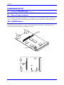
SW1: DPRAM Address
Under no circumstances should the SW1 ever be changed from the default settings of all the switches
CLOSED unless more than one Acc-54E are being used with the same UMAC. If more than one Acc54E is in the rack, SW1 must be set differently for each.
Hardware Setup
3
Acc-54E
SW-1
CLOSED
CLOSED
CLOSED
CLOSED
CLOSED
CLOSED
CLOSED
CLOSED
SW-2
SW-3
CLOSE
D
OPEN
CLOSE
D
CLOSE
D
OPEN
CLOSE
D
OPEN
CLOSE
D
OPEN
CLOSE
D
OPEN
SW-4
SW-5
SW-6
PMAC DPR Address
Range
CLOSED
CLOSED
CLOSED
$6C000-$6CFFF (default)
CLOSED
CLOSED
CLOSED
$74000-$74FFF
CLOSED
CLOSED
CLOSED
$6D000-$6DFFF
CLOSED
OPEN
CLOSED
CLOSED
CLOSED
CLOSED
$75000-$75FFF
$6E000-$6EFFF
OPEN
CLOSE
D
CLOSE
D
OPEN
OPEN
CLOSED
CLOSED
$76000-$76FFF
OPEN
CLOSED
CLOSED
$6F000-$6FFFF
OPEN
OPEN
CLOSED
CLOSED
$77000-$77FFF
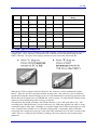
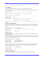
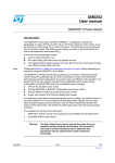
J1: USB Type B Receptacle
This connector is to be used in conjunction with USB A-B cable, which can be purchased from any local
computer store. The A connector is connected to a PC or Hub device; the B connector plugs into the
UMAC USB card. The figure below displays what the two ends on the cable should look like.
When the Acc-54E is purchased with the USB option, this connector is used to communicate with the
host PC. When the Acc-54E is purchased with the ethernet option, this connector is used to install and
upgrade microcontroller ethernet firmware for the Acc-54E communication card and to program the static
Internet Protocal (IP) address into an EEPROM that reads on startup. No cable should be attached to this
connector when communicaing to this accessory via ethernet.
The maximum cable length according to the USB Specification 1.1 for a full speed cable is 5m (~15ft).
According to the USB specification, you can connect up to five USB cables together with a hub, to create
a maximum length of 30m(~98ft). In addition, to extend the length of the USB connection there are USB
active extension cables available. Use a USB cable of high quality. Using higher quality USB cables,
some people have managed to operate up to 10m (30ft) cables without the use of an active extension cable
or hub. However, violating the specification by running a cable more than 5m is not recommended or
guarnateed.
4
Hardware Setup
Acc-54E
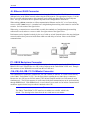
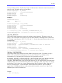
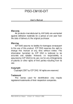
J6: Ethernet RJ45 Connector
This connector is used for ethernet communications from the UMAC to a PC. The PC must have a card
dedicated soley to the UMAC network when using the UDP protocol. The appropiate Category 5 10/100Base T network cable that mates to this connector can be readily purchased from any local computer
store. The type of network cable to purchase depends on the configuration to the host PC.
When making a direct connection to a Host communication Ethernet card in a PC a “cat 5 networking
crossover cable” must be used. A standard cat 5 straight through networking cable cannot be used in this
scenario. See left section of the figure below.
When using a connection to a network Hub or switch, the standard cat 5 straight through networking
cable must be used, and not a crossover cable. See right section of the figure below.
Performance can be degraded seriously by the use of a hub or switch. Network hubs or the more inteligent
network switches have processors inside them which can add delays of at least 15msec to the UMAC
communications.
P1: UBUS Backplane Connector
This connector is to be plugged into the UBUS backplane after the card is mated to the UMAC Turbo
PMAC2 CPU card. Therefore the Acc-54E is always adjacent to the Turbo PMAC2 CPU card. Through
this connector is how DPRAM is accessed from the Acc-54E card.
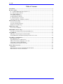
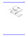
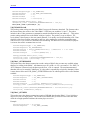
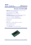
J1A,J1B,J2A,J2B: PC-104 Master Connector
This combination of connectors comprises the Acc-54E’s master PC104 Bus. It is used to mate directly
to the UMAC Turbo PMAC 2 CPU. See the figure below regarding how to mate the two connectors.
Because the Acc-54E acts as a PC104 master, a PC104 host computer and the Acc-54E cannot be used
simultaneously. The PC104 connector is used because backplane communications can be performed only
through DPRAM ascii. With DPRAM ascii, several software issues make it a far inferior communication
medium as opposed to the host port which is attached to the CPU.
Note:
The UMAC Turbo PMAC 2 CPU must have its address set to 0x210, which is the
default. The drawing below shows how the two cards mate to one another.
Hardware Setup
5
Acc-54E
6
Hardware Setup
Acc-54E
ETHERNET SOFTWARE SETUP
Accessory 54E IP Setup
Using the Acc-54E ethernet option requires Pewin Pro with at least Service Pack 3. Earlier revisions of
software are not capable of communicating with the ethernet option. Ethernet devices are configured by
launching the application EthConfigure.EXE, provided by Delta Tau as a part of the Pewin32PRO Suite
or any other Delta Tau standard installation. Installation and configuration of Ethernet devices is
independent of the operating system. Therefore, Ethernet devices are compatible with Windows NT 4.0 in
addition to Windows 98/ME/2000 and Windows XP.
To configure the Acc-54E side, run the application EthConfigure.EXE from the Programs\Pewin32PRO\
program group. This application is provided as part of the standard installation and is placed in
c:\Program files\Delta Tau\Common\ folder. The Acc-54E card comes preprogrammed with a default IP
(internet protocol) address of 192.6.94.5 stored in an on-board EEPROM. If you wish to change the IP
address stored in the EEPROM, you must plug in the USB cable to reconfigure the card after powering on
the UMAC.
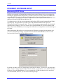
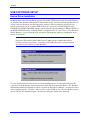
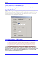
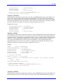
When launching the EthConfigure.exe program with the USB cable not plugged into the ethernet card,
you will see the following message. If you do not need to alter the default IP address of the Acc 54E
card, just click OK to the run the EthConfigure program.
By default, the address 192.6.94.5 should appear in the Store IP edit box. If it does not, you should enter
it there. If you are trying to alter the address from the default, you should enter your own IP in the Store
IP edit box. Press the Store IP button. If you are plugged in via USB, the addresss will be stored into
Acc-54E EEPROM; otherwise, you will see the following message.
Ethernet Software Setup
7
Acc-54E
You must press YES to store the IP address in the registsry so that software from the Pewin Pro Suite can
recognize the ethernet accessory as an available PMAC Device. Afterwards you will be presented with a
dialog box requesting that you enter which instance of the card you are setting the IP address for. This
number is changed from 0 to another number only when you are talking to multiple Acc-54Es
simultaneously from a single host. When doing so, the additional Acc-54E must be programmed with a
unique IP address.
Accessory 54E Protocol Setup
The Acc-54E cards default protocol is UDP. UDP has a little less overhead than TCP but should be
restricted to point-to-point applications and not be used on a LAN. UDP does not provide automatic
retransmittal of dropped packets due to network collisions, hubs, noise etc.
Using TCP (transmission control protocol) is recommended, TCP is a more robust protocol that can be
used on a network. TCP handles issues such as lost packets with automatic retransmattal. If you wish to
use the UMAC on a LAN the use of TCP is mandatory.
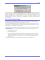
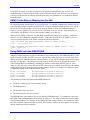
To use TCP it is necessary that the Acc54E be configured into TCP mode. The active protocol mode is
stored in EEPROM in the Acc54E using the EthConfigure.exe program supplied with PewinPro. To
configure the Acc54,
1) Plug a USB cable to Acc54E
2) Launch EthConfigure.exe.
3) Click the radio button labeled TCP in the Protocol Group Box (see picture below). This will
change the protocol mode of the Acc54E to TCP, and set up the Windows registry of the PC so
that the Pcomm32 library of Delta Tau opens a TCP coonnection when a program using the
Library executes.
After the protocol is configured, remove the USB cable and power cycle the UMAC card.
8
Ethernet Software Setup
Acc-54E
Windows OS TCP/IP Setup
Ethernet mode of communication is supported by dedicated network only. A network card must be
configured on the computer to which the PMAC connection is desired before going to the following steps.
Further, A crossover Ethernet cable or a private hub along with two straight cables is required for this
setup as is outlined in the RJ45 section of the Hardware Setup.
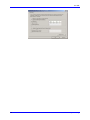
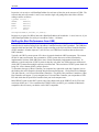
1) From the control panel, select properties of the network card you wish to communicate to PMAC
via Ethernet.
2) Highlight the Internet Protocol (TCPIP) and select properties.
3) Write the private area IP address (say 192.6.94.2) for this card and enter the subnet mask
(255.255.255.0) in the provided spaces.
4) Close the properties page and restart your computer. Your Ethernet card configuration on the
computer is complete. Note that the last digit in the IP address field must be a different value
from any IP address(es) set via the EthConfigure program.
Ethernet Software Setup
9
Acc-54E
10
Ethernet Software Setup
Acc-54E
USB SOFTWARE SETUP
Device Driver Installation
Starting with Pewin Pro with Service Pack 3, the USB driver support for this revision of the card is
bundled with the Pewin Pro installation program. The UMAC USB card will work only with Windows
98, Windows ME, Windows 2000 and in the future Windows XP. It will not function with Windows NT
4.0; this version of Windows does not support plug and play, which is required by all USB devices.
One file is placed on your PC to achieve USB connectivity – device driver PMACUSB.SYS in the
WINDOWS\SYSTEM32\DRIVERS directory and the plug and play information file PMACUSB.INF in
the WINDOWS\INF directory. When the UMAC is plugged into the PC, you will see a “New Hardware
Found” Message. A series of dialog boxes will appear, indicating that windows is installing the device
drivers for the system.
Note:
Plug in the USB cable from the UMAC to the PC after you have installed the software
Pewin Pro and its Service Pack 3. If you plug in the USB cable before you have installed
the software, you will have to restart Windows.
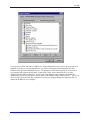
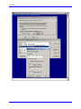
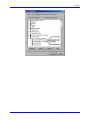
To verify that the software device drivers have been installed properly, you can right click on the My
Computer icon on the desktop. Select Properties from the drop down menu that appears. The Windows
tabbed dialog titled System Properties appears. Click the tab titled Device Manager. At this point a list of
device categories appears. Click the + and you will see a list of USB devices. Provided the device driver
for Acc-54E has been installed properly, you will see a dialog box similar to the following:
USB Software Setup
11
Acc-54E
If you do not see Delta Tau UMAC USB Device (Licensed Pmacusb.sys) the device driver has not been
installed; if you have a red x through that line or a yellow exclamation point through that line, then
Windows had a problem installing the device. The appropiate trouble shooting steps are to first reboot
you computer and examine this list again. If that doesn’t work, ensure that pmacusb.sys is in the
Windows\system32\Drivers directory. If this is true, when using an older computer check with the
manufacturer to make sure that there is not an update to the BIOS to enable USB on your PC. Also if you
do not see the Universal Serial Bus Controllers in your device manager dialog box, make sure that it is
enabled in the BIOS of your computer.
12
USB Software Setup
Acc-54E
PEWINPRO SOFTWARE SETUP
First Time User (Register the Newly Installed Devices)
1) Once the driver is installed it needs additional configuration by using the PmacSelect dialog. The
PmacSelect dialog is accessible by all programs created with PComm32Pro (via the PmacSelect()
function call). Launch the supplied Delta Tau application (Pewin32Pro, PMACTestPro, or any
application) from the program menu and display the PmacSelect dialog.
Product
To Display the PmacSelect Dialog
Pewin32Pro
From the main menu item setup go to Setup\General Setup and Options select the
Default Device tab. Press the Select button.
Pcomm32Pro
Run the supplied PmacTest application. From the main menu select
Configure\Communications. Also, you may call the PmacSelect() function from any
application you have coded.
PtalkDTPro
Call the SelectDevice() method of Ptalk from the supplied or self created programs.
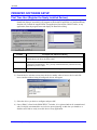
2) From the device selection screen select the device number where to insert a device and click
insert. Another window listing all configured devices will appear.
3) Select the device you desire to configure and press OK.
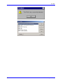
4) Once a PMAC is listed in the PMACSELECT window, it is registered and can be communicated
with. It is highly recommended to test a device upon registering. At this time you should see a
familiar screen and are ready to use this device in any application.
PEWINPRO Software Setup
13
Acc-54E
14
PEWINPRO Software Setup
Acc-54E
USING DPRAM
The Acc-54E contains its own on board DPRAM. This DPRAM can be used for automatic reporting
features or as general purpose scratch pad area for the users own custom data.
DPRAM for General Purpose Scratch Pad Data
The UMAC-Turbo can write to any DPRAM memory location on the Acc-54E. This can be done by
using M-Variables that point to an area in the address range defined in the “SW1:DPRAM Address” table
(p. 2) (usually $6C000 - $6CFFF). However, unpredictable results will occur if you write to the areas
that are used for the DPRAM automatic reporting features. The automatic reporting features memory
area can be determined from the Turbo Software Reference Manual by examining the address in the
$60000-$60FFF; however, when using Acc-54E, this range is from $6C000-$6CFFF. It is recommended
you start your own variables at the $6CD60; this address is well outside the range of the automatic
reporting features. Below is an example of pointing to a series of DPRAM locations on the USB card and
the count:
M1000->DP:$6CD60
M1001->Y:$6CD61
M1002->X:$6CD61
M1003->F:$6CD62
PmacDprGetMem(0,0x3580,4,&dwData)
PmacDprGetMem(0,0x3584,2,&wData1)
PmacDprGetMem(0,0x3586,2,&wData2)
PmacDprGetMem(0,0x3586,4,&fData)
The parameters passed to the function PmacDPRGetMem are:
•
The device number for the case of multiple devices.
•
The DPRAM offset.
•
The number of bytes to retrieve.
•
The location to place the retrieved bytes.
The DPRAM offset is the number of bytes from the base DPRAM location. To compute this value, take
the UMAC-Turbo DPRAM address and multiply its offset by 4. The offset is always the last three digits
of the DPRAM address. For example, for the address $6CD60 multiply $D60 by 4 to compute the offset;
the offset for PMAC address $6CD60 is 0x3580. For X memory address, the same applies, except that 2
must be added to the offset calculation.
In practice it is not wise to call PmacDprGetMem for each item of data, due to the structure of USB. The
reason is that each call can take 1 msec, but so would a single call getting all the data. More efficient
coding would be as follows
Typedef
DWORD
WORD
WORD
Float
struct {
dwData;
wData1;
wData2;
fData;
} Data;
PmacDprGetMem(0,0x3580,12,&Data);
Response to a request for 1KB of data with a PmacDprGetMem call can take a minimum of ~1 msec;
however, if you called PmacDprGetMem for each byte it would have taken at least ~1024msec.
Using DPRAM
15
Acc-54E
Setting DPRAM for Automatic Reporting Features for Acc-54E
The dip switch SW1 should always be configured with all of the switches set to the CLOSED position.
However, in the rare case that SW1 has been changed, the DPRAM address I24 must be changed to match
the address. This variable gives you the ability to use the automatic reporting features for the DPRAM.
If you are using a UMAC-Turbo that has on-board DPRAM, I24 will get reset to a value that does not
match the address determined by the switch SW1 when you perform a card reinitialization via the $$$***
command or by installing the E3 jumper on the Turbo PMAC2 CPU.
Note
To determine whether or not the UMAC Turbo has DPRAM, check for the presence of
U45 in the middle of the UMAC CPU board. If U45 is present, the UMAC Turbo has
DPRAM. If not, it does not.
To enable the DPRAM Automatic reporting features requires that the user turn on the DPRAM automatic
features for the device. To do this from Pewin Pro, go to the Setup Menu Item AND select the General
Setup and Options Menu Item. Then Click the Select button from the Default Device tab of the General
Setup and Options dialog box.
The PMAC Devices dialog will then appear from the list box highlight the appropiate device by clicking
it with the mouse. You can then click the Properites… button to open a dialog box you can use to enable
the DPRAM features.
Now you have the ability to Enable/Disable DPRAM automatic realtime/background function from the
SelectDevice menu. You may also want to set the update period and motor mask.
After turning on DPRAM automatic features you will have to exit Pewin Pro then restart it before the
automatic features will turn on. After doing this, the speed of response when running the executive,
problably will slow down slightly since the PC is now continually reading the automatic data from
DPRAM and placing it in PC memory.
16
Using DPRAM
Acc-54E
Using DPRAM
17
Acc-54E
18
Using DPRAM
Acc-54E
UPGRADING ACC-54E FIRMWARE
The Acc-54E can have its firmware upgraded via its USB port. This is useful for getting the latest
firmware to take advantage of bug fixes and new features.
Upgrading Bootloader
The bootloader contains the code necessary to load the application firmware from the local serial
EEPROM to the Acc-54E static RAM. This code rarely if ever will need to be upgraded or changed.
However, in the rare instance that this firmware needs to be upgraded, click the Store Boot button; you
will then be presented with an Oipen File dialog box. Select the boot loader firmware file with an iic
extension supplied by Delta Tau to upgrade this firmware.
Upgrading Ethernet or USB Firmware
CAUTION
Be especially careful not to stop the firmware upgrade in the middle of its loading and not
to load application firmware into the boot loader and not to load boot loader firmware in
the application firmware. Doing so will result in having to return the card to the factory
for repair.
Upgrading the application firmware can be done with the Store F/W button in the same fashion as the
boot loader firmware. Problably at some time you will need to upgrade this firmware. This firmware
contains all of the code that performs USB and Ethernet communciations. To upgrade the firmware, click
the Store F/W button. You will be presented with an Open File dialog box so that you can select the
version of firmware that you will load in to the Acc-54E.
Upgrading Acc-54E Firmware
19
Acc-54E
It is possible to change a card that you purchased for ethernet communications into one for USB
communications by downloading the USB version of firmware into the card. However, it is not possible
to change a USB card into an ethernet communication card, since additional ICs are needed for ethernet
communications.
UMAC-Turbo Memory Mapping for Acc-54E
Official support for the USB card is not in PMAC.DLL; however the USB card uses the same technique
for commmunicating with the PMAC as does an ISA card. To establish communication with the card, go
to the MotionExe program included with PEWIN32. Using the Add menu button for device zero, set up
the card as if it has a Port Address of 0x210, an Interrupt Address of None and a DPRAM Adress of
None. (If you have PEWIN 2.38 you may click the USB Mode check box instead). After doing this you
will be able to use PEWIN 32 just as if the card was a PMAC on an ISA bus.
When using the UMAC USB card, all of the BUS communication functions are available. In addition
there are a couple of DPRAM commands available. Using either PTALK DT or PCOMM 32 you can
write a program to interface to the UMAC through the following functions:
PVOID CALLBACK PmacDPRGetMem(DWORD dwDevice,DWORD offset,
size_t count,PVOID val )
PVOID CALLBACK PmacDPRSetMem( DWORD dwDevice, DWORD offset, size_t
count, PVOID val )
Using PMAC with the USB DPRAM
The UMAC-Turbo can write to any DPRAM memory location on the Acc-54E. This can be done by
using M-Variables that point to an area in the address range defined in the “SW1:DPRAM Address” table
(page 4) (usually $6C000 - $6CFFF). However, unpredictable results will occur if you write to the areas
that are used for the DPRAM automatic reporting features (ie., the ASCII communications buffer ranging
from $6C3A7-$6C410). The automatic reporting features memory area can be determined from the
Turbo Software Reference Manual by examining the address in the $60000-$60FFF; however, when
using Acc-54E, this range is from $6C000-$6CFFF. Start your own variables at the $6CD60; this address
is well outside the range of the automatic reporting features. Below is an example of pointing to a series
of DPRAM locations on the USB card and the count:
M1000->DP:$6CD60
M1001->Y:$6CD61
M1002->X:$6CD61
M1003->F:$6CD62
PmacDprGetMem(0,0x3580,4,&dwData)
PmacDprGetMem(0,0x3584,2,&wData1)
PmacDprGetMem(0,0x3586,2,&wData2)
PmacDprGetMem(0,0x3586,4,&fData)
The parameters passed to the function PmacDPRGetMem are:
•
The device number for the case of multiple devices.
•
The DPRAM offset.
•
The number of bytes to retrieve.
•
The location to place the retrieved bytes.
The DPRAM offset is the number of bytes from the base DPRAM location. To compute this value, take
the UMAC-Turbo DPRAM address and multiply its offset by 4. The offset is always the last three digits
of the DPRAM address. For example, for the address $6CD60 multiply $D60 by 4 to compute the offset;
the offset for PMAC address $6CD60 is 0x3580. For X memory address, the same applies, except that 2
must be added to the offset calculation.
20
Upgrading Acc-54E Firmware
Acc-54E
In practice it is not wise to call PmacDprGetMem for each item of data, due to the structure of USB. The
reason is that each call can take 1 msec, but so would a single call getting all the data. More efficient
coding would be as follows
typedef struct {
DWORD
dwData;
WORD
wData1;
WORD
wData2;
Float
fData;
}
Data;
PmacDprGetMem(0,0x3580,12,&Data);
Response to a request for 1KB of data with a PmacDprGetMem call would take ~1 msec; however, if you
called PmacDprGetMem for each byte it would have taken ~1024msec.
Getting the Best Performance from USB
To be assured of the best possible performance when using USB communications, use a USB Host
controller that is made according to the Open Host Controller Interface (OHCI) standard. The USB Host
controller built into Intel and VIA Chipsets is made according to the Universal Host Controller Interface
(UHCI) standard. All other chipsets ie. (ALi, SiS etc.) use USB Host Controllers that conform to the
OHCI standard.
Typically, the UHCI systems operate 25% slower in practice than their OHCI counterparts. The reasons
for this are many and complex, but to summarize, UHCI systems have more of their functionality
implemented in software while OHCI have more of their functionality implemented in hardware. In
addition, a typical restriction of UHCI systems is that they only allow one USB request per millisecond,
while OHCI systems allow multiple requests per millisecond. This restriction of UHCI systems leads to it
being 25% slower than an OHCI system in practice.
To determine what type of Host Controller your computer has, right-click on the My Computer icon on
the desktop; then select Properties from the drop down menu that appears. Click on the Device Manager
Tab, and select the + on Universal Serial Bus Controllers. The phrase Universal Host Controller or Open
Host Controller will appear. If your computer has a Universal Host Controller you can purchase a USB
PCI card which has an Open Host Controller from your local computer store.
Most USB PCI cards use the OHCI system; only if the chipset used on the USB PCI card is VIA is the
card not an OHCI card. To be certain that the USB PCI card is an OHCI, get a card that is Macintosh
compatible; this will assure you that the card is OHCI compatible.
Upgrading Acc-54E Firmware
21
Acc-54E
22
Upgrading Acc-54E Firmware
Acc-54E
PMAC ETHERNET PROTOCOL
Introduction
This section is intended for application programmers who have a fundamental understanding of Berkley
sockets used in the TCP/IP protocol suite. Before any attempt to read or understand the contents of this
manual one should review basic sockets and understand them before proceeding. The fundamental socket
functions that must be understood are recv,send and socket.
The examples in this manual are for demonstration purposes only and are to there to convey the concepts
of how to communicate to the Delta Tau card. Therefore, the examples do not include error checking and
timeouts. Delta Tau’s actual production code does, however, and application programmers are strongly
encouraged to include error checking and timeouts in their code to prevent hangups and unresponsive
behavior.
The PMAC embeddeded ethernet communications card talks using either the UDP or TCP protocol of the
TCP/IP suite of protocols on port 1025. 9See the section on protocol setup.) Therefore the programmer
should open a datagram socket on the port 1025, the PMACPORT.
sock = socket(PF_INET,SOCK_DGRAM,0);// change SOCK_DGRAM to
SOCK_STREAM for TCP
// Embedded Ethernet's IP address
// The port that the embedded program is listening on.
sin.sin_port = htons(PMACPORT);
connect(*sock,(struct sockaddr*)&sin,sizeof(sin));
PMAC Ethernet Protocol Command Packet Description
Command Packets. All commands are sent over the socket in the form of the following structure:
/ Ethernet command structure
typedef struct tagEthernetCmd
{
}
BYTE
RequestType;
BYTE
Request;
WORD
wValue;
WORD
wIndex;
WORD
wLength;
BYTE
bData[1492];
ETHERNETCMD,*PETHERNETCMD;
The following is a description of the fields in the ETHERNETCMD structure.
RequestType is used in certain commands to indicate whether the request is an input with respect to the
PC or an output command with respect to the PC.
Delta makes the following defines VR_UPLOAD = 0xC0 for a command sent to host and
VR_DOWNLOAD = 0x40 for a command sent to the device.
PMAC Ethernet Protocol
23
Acc-54E
Request indicates what type of command you are requesting from the PMAC ethernet connection0
Below is a list of defines for the currently supported command set.
#define VR_PMAC_SENDLINE
0xB0
#define VR_PMAC_GETLINE
0xB1
#define VR_PMAC_FLUSH
0xB3
#define VR_PMAC_GETMEM
0xB4
#define VR_PMAC_SETMEM
0xB5
#define VR_PMAC_SETBIT
0xBA
#define VR_PMAC_SETBITS
0xBB
#define VR_PMAC_PORT
0xBE
#define VR_PMAC_GETRESPONSE
0xBF
#define VR_PMAC_READREADY
0xC2
#define VR_CTRL_RESPONSE
0xC4
#define VR_PMAC_GETBUFFER
0xC5
#define VR_PMAC_WRITEBUFFER
0xC6
#define VR_PMAC_WRITEERROR
0xC7
#define VR_FWDOWNLOAD
0xCB
#define VR_IPADDRESS
0xE0
wValue is Request specific, and its use is indicated in under the description of each command.
wLength indicates the length of the bData field below.
bData is the meaningful data that is sent to the PMAC.
Every command that is sent to the Acc 54E begins uses the ETHERNETCMD packet structure and is
initiated with a PC send command. Every command then must issue a recv command to either receive an
acknowledgement character back via the recv command or receive meaningful data.
#define ETHERNETCMDSIZE 8
send(sock,(char *)&EthCmd,ETHERNETCMDSIZE,0);
recv(sock,(char *)&EthCmd,1,0);
PMAC Ethernet Protocol Command Set
VR_PMAC_FLUSH
This packet causes a ^X to be issued to the PMAC and will wait up to 10 msec for PMAC to respond with
a ^X. command with respect to the PC. The packet that is sent should be set up as follows. One byte
will be returned upon successful completion of the command.
EthCmd.RequestType = VR_DOWNLOAD;
EthCmd.Request
= VR_PMAC_FLUSH;
EthCmd.wValue
= 0;
EthCmd.wIndex
= 0;
24
PMAC Ethernet Protocol
Acc-54E
EthCmd.wLength
= 0;
EthCmd.bData – not used for this command
Example :
int CALLBACK PmacSockFlush()
{
ETHERNETCMD EthCmd;
int
rc,iTimeout;
EthCmd.RequestType = VR_DOWNLOAD;
EthCmd.Request
= VR_PMAC_FLUSH;
EthCmd.wValue
= htons(FLUSH_TIMEOUT);
EthCmd.wIndex
= 0;
EthCmd.wLength
= 0;
send(sock,
(char *)&EthCmd,
ETHERNETCMDSIZE ,
0);
recv(sock,
(char *)&EthCmd,
1,
0);
}
The above example and all of the examples in this document do not perform error checking and timeout
checking. It is the application developer's responsibilty to perform error checking and timeout checks to
insure that his/her application does not hang.
VR_PMAC_SENDLINE
This packet causes the string NULL terminated in EthCmd.bData to be sent to the PMAC. The string
should not be terminated with a carriage return as this is done by the firmware. One byte will be returned
upon successful completion of the command.
EthCmd.RequestType = VR_DOWNLOAD;
EthCmd.Request
= VR_PMAC_SENDLINE;
EthCmd.wValue
= 0;
EthCmd.wIndex
= 0;
EthCmd.wLength
= htons( (WORD)strlen(outstr));
strncpy((char *)&EthCmd.bData[0],
outstr
,(WORD)strlen(outstr));
Example :
int CALLBACK PmacSockSendLine(char *outstr)
{
EthCmd.RequestType = VR_DOWNLOAD;
EthCmd.Request
= VR_PMAC_SENDLINE;
EthCmd.wValue
= 0;
EthCmd.wIndex
= 0;
EthCmd.wLength
= htons( (WORD)strlen(outstr));
strncpy((char *)&EthCmd.bData[0],outstr,(WORD)strlen(outstr));
send(sock,
PMAC Ethernet Protocol
25
Acc-54E
(char *)&EthCmd,
ETHERNETCMDSIZE + strlen(outstr),
0);
recv(sock,(char *)&EthCmd,1 ,0);
}
VR_PMAC_GETLINE
This packet causes the ethernet connection to return any available string that may be residing in the
PMAC. All characters up to a <CR>,<ACK> or <LF> are returned. The available string in PMAC is
returned and should be captured via an ethernet recv command. It is recommended that this function not
be used. Use VR_PMAC_GETBUFFER instead, as this function will retreive multiple lines and will
greatly enhance performance as opposed to using multiple calls of VR_PMAC_GETLINE
EthCmd.RequestType
EthCmd.Request
EthCmd.wValue
EthCmd.wIndex
EthCmd.wLength
= VR_UPLOAD;
= VR_PMAC_GETLINE;
= 0;
= 0;
Not used
Example :
int CALLBACK PmacSockGetLine(char *instr)
{
EthCmd.RequestType = VR_DOWNLOAD;
EthCmd.Request
= VR_PMAC_GETLINE;
EthCmd.wValue
= 0;
EthCmd.wIndex
= 0;
EthCmd.wLength
= htons( (WORD)strlen(outstr));
strncpy((char *)&EthCmd.bData[0],outstr,(WORD)strlen(outstr));
send(sock,(char *)&EthCmd,ETHERNETCMDSIZE,0);
recv(sock,(char *)&instr,255 ,0);
}
VR_PMAC_GETBUFFER
This packet causes the ethernet connection to return any available string that may be residing in the
PMAC. All characters up to an <ACK> or <LF> are returned. If a <BEL> or <STX>character is
detected only the data up to the next <CR> is returned. The maximum amount of data that will ever be
returned is 1400 Bytes. It is the callers responsibility to logically determine if there is more data to follow
and if VR_PMAC_GETBUFFER must be called again to retrieve all of the data available.
EthCmd.RequestType
EthCmd.Request
EthCmd.wValue
EthCmd.wIndex
EthCmd.wLength
EthCmd.bData
=
=
=
=
=
-
VR_UPLOAD;
VR_PMAC_GETBUFFER;
0;
0;
htons( (WORD)strlen(outstr));
Not Used
Example :
int CALLBACK PmacSockGetBuffer(char *instr)
{
EthCmd.RequestType = VR_DOWNLOAD;
EthCmd.Request
= VR_PMAC_GETBUFFER
EthCmd.wValue
= 0;
EthCmd.wIndex
= 0;
EthCmd.wLength
= htons( (WORD)strlen(outstr));
send(sock,(char *)&EthCmd,ETHERNETCMDSIZE,0);
26
PMAC Ethernet Protocol
Acc-54E
recv(sock,(char *)&instr,1400,0);
}
VR_ IPADDRESS
This packet permits either setting or retreival of the current IP address in the Acc 54E.
When setting the IP address to a new value it is required that the Acc 54E be powered down for the new
address to take effect.
EthCmd.RequestType = VR_UPLOAD to retreive the IP address
or
EthCmd.RequestType = VR_DOWNLOAD to set the IP address
EthCmd.Request
EthCmd.wValue
EthCmd.wIndex
EthCmd.wLength
EthCmd.bData
=
=
=
=
=
VR_IPADDRESS;
0;
0;
htons(4);
contains 4 bytes of data indicating the IP
address set on the send command.
For the receive command 4 bytes of data are returned indicating the IP
address.
VR_PMAC_SENDCTRLCHAR
This packet permits sending of a single character or control character to the Acc 54E. The packet below
is what is to be sent. The data received is irrelevant; its purpose is to insure the sender's command was
received.
EthCmd.RequestType
EthCmd.Request
EthCmd.wValue
EthCmd.wIndex
EthCmd.bData
=
=
=
=
-
VR_DOWNLOAD;
VR_PMAC_SENDCTRLCHAR;
htons(outch); // the character to write
0;
Not Used
VR_PMAC_PORT
This packet permits sending of a single byte or receiving of single byte from the Acc-54E via the Turbo
PMAC 2 CPU host port.
To send data to the host port set the packet as follows. After sending the packet the programmer must wait
to receive 1 byte via the recv function before continuing. The data received is irrelevant; its purpose is to
insure the sender's command was received.
EthCmd.RequestType = VR_DOWNLOAD;
EthCmd.Request
= VR_PMAC_PORT;
EthCmd.wValue
= htons((WORD)offset);
EthCmd.wIndex
= htons((WORD)outch);
EthCmd.wLength
= 0;
To receive data from the host port set the packet as follows. After sending the packet the programmer
shall receive 1 byte which is the value the Acc-54E read from the Turbo PMAC 2 CPU host port.
EthCmd.RequestType
EthCmd.Request
EthCmd.wValue
EthCmd.wIndex
EthCmd.wLength
=
=
=
=
=
VR_UPLOAD;
VR_PMAC_PORT;
htons(offset);
0;
0;
VR_PMAC_READREADY
This packet permits determining if there is data on the Turbo PMAC 2 CPU ready to be read.
PMAC Ethernet Protocol
27
Acc-54E
Two bytes will be returned. The first byte if non zero indicates there is data to be read; if zero, there is no
data to be read. The packet will be set up as follows.
EthCmd.RequestType = VR_UPLOAD;
EthCmd.Request
EthCmd.wValue
EthCmd.wIndex
EthCmd.wLength
=
=
=
=
VR_PMAC_READREADY;
0;
0;
htons(2);
Example :
ETHERNETCMD EthCmd;
char
int
data[2];
rc;
EthCmd.RequestType
EthCmd.Request
EthCmd.wValue
EthCmd.wIndex
EthCmd.wLength
=
=
=
=
=
VR_UPLOAD;
VR_PMAC_READREADY;
0;
0;
htons(2);
rc = send(sock,((char *)&EthCmd),ETHERNETCMDSIZE,0);
rc = recv(*((SOCKET *)vh[dwDevice].hDriver),data,2,0);
return data[0];
VR_CTRL_REPONSE
This packet permits obtaining the response after sending a control character. The packet is set up as
follows. The received data is the response to the sent control character. Meaningful data is returned for
the following control characters ^B,^C,^F,^G,^P and ^V. All other data control characters do not return
meaningful data.
EthCmd.RequestType = VR_UPLOAD;
EthCmd.Request
EthCmd.wValue
EthCmd.wIndex
EthCmd.wLength
= VR_CTRL_RESPONSE;
= htons(outchar);//outchar=ctrl char to send out
= 0;
= htons(len);
rc = send(sock,((char *)&EthCmd),ETHERNETCMDSIZE,0);
rc = recv(sock,outstr,len,0); // returned data appears
VR_PMAC_WRITEBUFFER
This packet permits writing multiple lines to the PMAC with just one packet. The packet is set up as
follows. The received data is the response to the sent control character. It is usually used for
downloading a file. Data should be of the form each line seperated by null byte.
For Example, OPEN PLC 1 CLEAR<00>P1=P1+1<00>CLOSE<00> where <00> indicates a null byte.
The maximum data length is 1024; anything bigger must be separated into multiple calls of
VR_PMAC_WRITEBUFFER. Upon receiving this packet the Acc-54E sends back 4 bytes of data. Byte
3 indicates if there was an error downloading. If the value of this byte is 0x80, there was an error during
the download. If it is 0, there was no error during download. Byte 2 indicates the Pmac Error type if
there was a download error. Consult the PMAC Software Reference under I6. Bytes 0 and Byte 1
together form a WORD that indicates the line number which caused the error to occur. Byte 1 is the
MSB and Byte 0 is the LSB of that word.
Example:
char errcode[4];
28
PMAC Ethernet Protocol
Acc-54E
EthCmd.RequestType
EthCmd.Request
EthCmd.wValue
EthCmd.wIndex
EthCmd.wLength
=
=
=
=
=
VR_DOWNLOAD;
VR_PMAC_WRITEBUFFER;
0;
0;
htons(len) ;
memcpy(EthCmd.bData,data, len);
send(sock,(char *)&EthCmd,ETHERNETCMDSIZE + len,0);
recv(sock,(char *)errcode,4 ,0);
VR_FWDOWNLOAD
This packet permits writing raw data to the PMAC host port for firmware download. The firmware takes
the stream of data, then writes to the Turbo PMAC 2 CPU host port at address 5,6 and 7. The packet
includes in the wValue parameter to command to start the download at host port address 5. . This packet
permits writing multiple lines to the PMAC with just 1 packet. The packet is set up as follows. The
received data is the response to the sent control character. It is usually used for downloading a file. Data
should be of the form each line seperated by null byte. After sending the packet the programmer must
wait to receive 1 byte via the recv function before continuing. The data received is irrelevant; its purpose
is to insure the sender's command was received.
EthCmd.RequestType = VR_DOWNLOAD;
EthCmd.Request= VR_FWDOWNLOAD;
EthCmd.wValue = htons((WORD)bRestart); //bRestart = 1 on start
EthCmd.wIndex
= 0;
EthCmd.wLength
= htons((WORD)len) ;
memcpy(EthCmd.bData,data, len);
send(sock,(char *)&EthCmd,ETHERNETCMDSIZE + len,0);
recv(sock,(char *)&errcode,1 ,0);
VR_PMAC_GETRESPONSE
This packet causes the ethernet connection to send a string to PMAC, then to return any available strings
that may be residing in the PMAC. All characters up to an <ACK> or <LF> are returned. If a <BEL> or
<STX>character is detected, only the data up to the next <CR> is returned. The maximum amount of
data that will ever be returned is 1400 Bytes. It is the caller's responsibility to logically determine if there
is more data to follow and if VR_PMAC_GETBUFFER needs to be called again to retrieve all of the data
available.
EthCmd.RequestType = VR_DOWNLOAD;
EthCmd.Request
= VR_PMAC_GETRESPONSE;
EthCmd.wValue
= 0;
EthCmd.wIndex
= 0;
EthCmd.wLength
= htons( (WORD)strlen(outstr));
strncpy((char *)&EthCmd.bData[0],outstr,(WORD)strlen(outstr));
send(sock,(char*)&EthCmd,ETHERNETCMDSIZE + strlen(outstr),0);
recv(sock, szPmacData,1400,0);
VR_PMAC_GETMEM
This packet causes the ethernet connection to retrieve DPRAM data from the PMAC. Up to 1400 bytes
may be received in a single packet. The wValue field contains the byte offset to retreive the data from,
while the wLength parameter indicates how many bytes to receive.
Example:
EthCmd.RequestType = VR_UPLOAD;
EthCmd.Request
PMAC Ethernet Protocol
= VR_PMAC_GETMEM;
29
Acc-54E
EthCmd.wValue
EthCmd.wIndex
EthCmd.wLength
= htons(offset);
= 0;
= htons(length);
//
send(sock,(char *)&EthCmd,ETHERNETCMDSIZE ,0);
recv(sock,(char *)data,1400,0);
VR_PMAC_SETMEM
This packet causes the ethernet connection to write data to the DPRAM shared between the PMAC and
the Acc-54E. Upto 1400 bytes may be written in a single packet. The wValue field contains the byte
offset to write the data to while the wLength parameter indicates how many bytes to write. After sending
the packet the programmer must wait to receive 1 byte via the recv function before continuing. The data
received is irrelevant; its purpose is to insure the sender's command was received.
Example packet setup:
EthCmd.RequestType
EthCmd.Request
EthCmd.wValue
EthCmd.wIndex
EthCmd.wLength
=
=
=
=
=
VR_UPLOAD;
VR_PMAC_SETMEM;
htons(offset);
0;
htons(length);
VR_PMAC_SETBIT
This packet causes the ethernet connection to perform a write to DPRAM shared between the PMAC and
the Acc-54E that either sets bits in a 32-bit word or clears bits in a 32-bit word. If the wIndex parameter
is supplied with a 1, a logical OR is performed that sets bits. If it is 0, a logical AND is performed, which
clears bits. It is the programmers responsibility to use the appropiate mask for setting or clearing bits.
The wValue field contains the byte offset to retreive the data from. After sending the packet the
programmer must wait to receive 1 byte via the recv function before continuing. The data received is
irrelevant; its purpose is to insure the sender's command was received.
Example :
DWORD
mask = 0x00000001;
EthCmd.RequestType
EthCmd.Request
EthCmd.wValue
EthCmd.wIndex
EthCmd.wLength
=
=
=
=
=
VR_UPLOAD;
VR_PMAC_SETBIT;
htons((WORD)offset);
htons((WORD)on);
htons(len);
// generate the mask
mask <<= bitno; // zero based
// If clearing a bit compliment mask to prepare the firmware for AND
if(!on)
mask = ~mask;
memcpy(EthCmd.bData,&mask,len);
// Send command request
send(sock,(char *)&EthCmd,ETHERNETCMDSIZE+len,0);
recv(sock,(char *)&errcode,1,0);
VR_PMAC_SETBITS
This packet causes the ethernet connection to perform a write to DPRAM shared between the PMAC and
the Acc-54E that sets bits in a 32-bit word to a new value. The wValue field contains the byte offset to
30
PMAC Ethernet Protocol
Acc-54E
retreive the data from. The bData field of the ethernet command packet must be stuffed with a mask
indicating which bits to set in four bytes followed by four bytes that indicate the bits to clear in a 32-bit
word. After sending the packet the programmer must wait to receive 1 byte via the recv function before
continuing. The data received is irrelevant; its purpose is to insure the sender's command was received.
Example :
EthCmd.RequestType
EthCmd.Request
EthCmd.wValue
EthCmd.wIndex
EthCmd.wLength
=
=
=
=
=
VR_UPLOAD;
VR_PMAC_SETBITS;
htons((WORD)offset);
0;
htons(2*sizeof(DWORD));
temp = 0xFF03FFFF ;
memcpy(EthCmd.bData,&temp,sizeof(DWORD));
temp = 0x00030000 ;
memcpy(EthCmd.bData + 4,&temp,sizeof(DWORD));
// Send command request
send(sock,(char *)&EthCmd,ETHERNETCMDSIZE + 2*sizeof(DWORD),0);
recv(sock,(char *)&errcode,1,0);
PMAC Ethernet Protocol
31