1
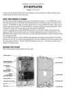
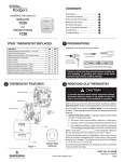
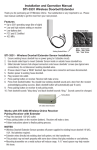
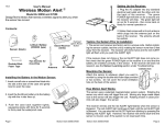
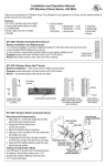
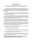
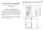
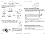
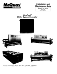
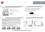
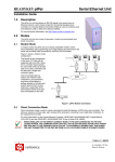
Installation and Operation Manual
STI Wireless Driveway MonitorTM
Part of the Wireless Alert Series
Models: STI-34150 - Battery Power Kit
STI-34100 - Solar Power Kit
STI-34151 - Battery Powered Sensor
STI-34101 - Solar Power Sensor
Thank you for purchasing the STI Wireless Driveway Monitor. Your satisfaction is very important to us.
Please take the time to read this manual carefully to get the most from your new product.
How the products works:
Because of its patented magnetometer sensor transmitter system, the Driveway Monitor will only be
triggered by cars or trucks - not people, animals and so forth. When a vehicle passes the Motion Alert®
Sensor Transmitter next to the driveway, the receiver unit inside the office or home sounds a chime
and flashes the alert light. The earth has a uniform magnetic field around it. A vehicle creates a slight
disturbance in the earth’s field. The sensor transmitter detects this disturbance and transmits a signal
to the receiver.
Before you start:
Refer to this drawing to become familiar with all the parts.
SENSOR
TRANSMITTER
CAP
SENSOR TRANSMITTER
2 “C” BATTERIES
(NOT INCLUDED)
SENSOR
TRANSMITTER
SENSOR
TRANSMITTER
BASE
MOUNTING
TUBE CAP
WALL MOUNT (INCLUDED)
NOT NEEDED FOR POLE
MOUNT INSTALLATION
SENSOR
TRANSMITTER
BOTTOM
MOUNTING
TUBE CAP
12” MOUNTING TUBE
RECHARGEABLE
NiMH BATTERIES
SENSOR TRANSMITTER
BOTTOM SCREWS
WALL MOUNT (INCLUDED)
NOT NEEDED FOR POLE
MOUNT INSTALLATION
12” MOUNTING TUBE
MOUNTING STAKE
MOUNTING STAKE
BATTERY POWERED SENSOR
TRANSMITTER
SOLAR POWERED SENSOR
TRANSMITTER
—1—
12”MOUNTING TUBE
Install batteries into the sensor transmitter
DRIVEWAY
Battery Powered (STI-34150 & STI-34151):
25' OR MORE
NG STAKE
PLACE SENSOR
TRANSMITTER 3' OR
LESS FROM EDGE OF
DOAND
NOT25+
DRIVEWAY
PULL ANTENNA!
FEET OR MORE FROM
STREET.
3' OR
LESS
ACE SENSOR
1. Remove the sensor transmitter cap by turning it counterclockwise.
ANSMITTER 3' OR
WITHOUT
PULLING ON THE BRASS ANTENNA OR ANY WIRES, grasp the outside of
SS FROM2.
EDGE
OF
MOUNTING STAKE
RIVEWAY ANDthe
25'battery/circuit board holder
by the finger notches, twist gently and pull out. Insert
R MORE FROM
STREET.
two
“C” alkaline batteries (not included).
TENNA
3' OR
LESS
SENSITIVITY
ADJUSTMENT
DRIV
25' OR MORE
3. Replace the battery holder/sensor transmitter and sensor transmitter cap.
4. To test or program sensor transmitter, place the sensor transmitter on a table or
counter approximately
5-10 ft.
REMOVE PLASTIC
TABaway from the receiver. Sensor transmitter can be
MITTER CAP
SENSOR
TRANSMITTER
activated byFROM
rotating
and will make a faint clicking noise to verify operation.
BATTERIES
2 “C” BATTERIES
5. Sensor should be(NOT
programmed
INCLUDED) to receiver before mounting outdoors. Refer to
receiver instructions for programming. (Model STI-34150 is factory programmed for
DO NOT REMOVE PLASTIC TAB
your convenience.)
TTER BASE
FINGER NOTCHES
FROM BATTERIES
SENSOR TRANSMITTER
PULL ANTENNA!
Sensitivity Adjustment:
WALL MOUNT (INCLUDED)
12'
MAX
RECHARGEABLE NiMH BATTERIES
SENSOR TRANSMITTER BOTTOM
SCREWS
DO NOT WALL MOUNT (INCLUDED)
PULL ANTENNA!
NOT NEEDED FOR POLE
MOUNT INSTALLATION
RECEIVER
ANTENNA
SENSOR
TRANSMITTER
jumper positionBOTTOM
inside the
NOT (HIGH)
NEEDED may
FOR POLE
The factory default setting
be adjusted by changing the
MOUNT INSTALLATION
SENSITIVITY
sensor transmitter.
ADJUSTMENT
MOUNTING
1. Unscrew cap.
SPEAKER
TUBE CAP
2.
Position
the
jumper
to
desired
sensitivity
(as
shown).
GREEN
BUTTON
ACE
SENSOR
TON
LED
SENSITIVITY
ANSMITTER
•
LOW: Position jumper on the two bottom pegs. FINGER
3' OR
NTING
TUBE
NOTCHES
SENSOR RED LED
ADJUSTMENT
ED FROM
LED EDGE OF
SS
TRANSMITTER
•
MEDIUM:
Completely
remove
jumper
or
hang
on
middle
peg.
SENSOR TRANSMITTER
12”MOUNTING
TUBE
RIVEWAY AND 25'
CAP
2 “C” BATTERIES
R MORE FROM
• STREET.
HIGH: Position jumper on the two top pegs.
STI-34104
TRANSISTOR
(NOT INCLUDED)
INDOOR
3.RECEIVER
Replace cap.
FINGER NOTCHES
OUTPUT JACK
UNTING
BE CAP
Medium Sensitivity Setting:
Low Sensitivity Setting:
UNTING STAKE
•
•
•
SENSOR
TRANSMITTER
BASE
ANTENNA CONNECTOR
•
•
•
POWER CONNECTOR
NNA CONNECTOR
Jumper LocationRECEIVER ANTENNA
MOUNTING
Jumper LocationTUBE CAP
SENSIT
(BA
High Sensitivity Setting:
•
•
•
MOUNTING STAKE
WALL MOUNT (INCLUDED)
Jumper
Location
NOT NEEDED
FOR POLE
S
TRANSM
S
TRANSM
B
MOUNT INSTALLATION
MOUN
TUB
SPEAKER
TENNA
L
H
L
H
RECEIVER
ANTENNA
Solar GREEN
Powered (STI-34100 & STI-34101):12” MOUNTING
TUBE
BUTTON
L
12” MOUN
1. RemoveLED
the bottom of the sensor transmitter by removing the 3 screws on the
RED LED
SENSITIVITY JUMPERS
SENSITIVITY JUMPERS
bottom of the unit.
SPEAKER (BATTERY TYPE)
REMOVE
PLASTIC
(SOLAR
TYPE)TAB
2. Remove the plastic tab between the batteries.
FROM BATTERIES
GREEN
BUTTON
TON
3. Replace the bottom of the unit and secure with the 3 screws.
RANSISTOR
LED Place the sensor
RED LED
UTPUT
MOUNTING STAKE
ED LEDJACK transmitter in direct sunlight for 48 hours.
OR
4. Place batteries in a NiMH (nickel
metal
hydride) battery charger (before using). Once
POWER CONNECTOR
ANTENNA TRANSISTOR
CONNECTOR
STI-34104
charged, return the batteries
12’to the sensor transmitter. Replace the bottom and secure with the 3 screws.
INDOOR RECEIVER
OUTPUT
JACK
PLACE SENSOR
MAX
3’OR transmitter,
5. To test or program sensor
place the 3'sensor
transmitter on a table or counter approximately 5-10 ft. away from
TRANSMITTER
OR
LESS
LESSbe
FROM
EDGE OF by rotating and will make a faint clicking noise to verify operation.
the receiver. Sensor transmitter can
activated
25' OR MORE
DRIVEWAY
AND 25'
POWER CONNECTOR
CONNECTOR
NNA CONNECTOR
DRIVEWAY
6. Sensor should be programmed
to receiver
before
outdoors. ReferANTENNA
to receiver
instructions for programming. (Model
OR MORE
FROM mounting
STREET.
STI-34100 is factory programmed for your convenience.)
L
SENSIT
MOUN
(BA
B
Sensitivity Adjustment:
The factory default setting (HIGH) may be adjusted by changing the jumper position inside
the sensor transmitter.
1. Remove the bottom of the sensor transmitter by removing the 3 screws on the bottom
STI-30104
LAMP CONTROLLER
of the unit.
(OPTIONAL)
2.
Position the jumper to desired sensitivity (as shown below).
AC ADAPTER
• LOW: Position jumper onRECEIVER
the twoANTENNA
leftmost pegs.
• MEDIUM: Completely remove jumper or hang from middle peg.
• HIGH: Position jumper on theSPEAKER
two rightmost pegs.
3. Replace the bottom
of
the
unit
and
secure with the 3 screws.
GREEN
LED
Low Sensitivity Setting:
RANSISTOR
UTPUT JACK
Medium Sensitivity Setting:
RED LED
STI-34104
INDOOR RECEIVER
Jumper Location
—2—
POWER CONNECTOR
ANTENNA CONNECTOR
+
-
B
RECEIVER ANTENNA
SENSITIVITY
ADJUSTMENT
SPEAKER
GREEN
LED
BUTTON
High Sensitivity Setting:RED LED
•
•
•
•
•
•
•
•
•
Jumper Location
BUTTON
+
TRANSISTOR
OUTPUT JACK
POWER CONNECTOR
Jumper Location
ANTENNA CONN
Installation Instructions:
MOUNTING
TUBE CAP
To obtain optimal range:
MOUNTING STAKE
WALL MOUNT (INCLUDED)
MOUNTING STAKE
NOT NEEDED FOR POLE
MOUNT INSTALLATION
The Solar Sensor Transmitter must be placed in an area that receives partial or full sunlight. For both models, be sure the
location of the sensor transmitter is at least 25’ back from the main road. For a typical 12’ wide driveway, it is recommended
12”MOUNTING
TUBE
the sensor transmitter be no more than 3’ away from the driveway
(see drawing).
Additional sensor transmitters may be required
for driveways exceeding 12’. Sensor transmitter may be placed up to 1,000 feet away from receiver; however, range may vary
depending upon environment and use of wireless telephones, wireless routers and other similar devices.
1. Place cap on tube.
2. Insert stake to opposite end of tube.
3. Place the tube (stake side down) into the ground within 3’ of the driveway
and more than 25’ from the road.
4. Gently hammer the cap side of the tube until stake is firmly in the ground.
5. Remove cap and place sensor transmitter on tube.
6. The sensor transmitter should have a clear line-of-site to the receiver to
improve performance.
7. Place the sensor transmitter so the vehicle does not pass between it and
the receiver.
STI recommends the use of the stake and tube included with your Driveway
Monitor. However, if you choose to mount the unit to an alternate mounting
device, please be sure the device is stable. STI does not recommend
mounting the sensor transmitter to a tree or a metal fence or gate.
TROUBLE
The RECEIVER does
not sound when a
vehicle passes.
25' OR MORE
3’OR
LESS
25' OR MORE
12’
MAX
DRIVEWAY
STI-30104
LAMP CONTROLLER
(OPTIONAL)
PLACE SENSOR
AC ADAPTER
TRANSMITTER 3' OR
LESS FROM EDGE OF
DRIVEWAY AND 25'
OR MORE FROM STREET.
GREE
LE
SOLUTION
TRANSISTOR
OUTPUT JACK
STI-30104
1. Check that the receiver is not in Temporary
or Permanent Silent Mode (red LED solid).
LAMP CONTROLLER
(OPTIONAL)
2. Check the sensor transmitter by picking
it up and rotating it. The sensor transmitter should make
AC ADAPTER
POWER CONNECTOR
a “faint clicking” noise.
RECEIVER ANTENNA
3. Check that the sensor transmitter and receiver are within operating distance from each other.
4. Check the sensor transmitter batteries and replace if necessary.
5. Reprogram the receiver using the steps in “Clearing the receiver memory”SPEAKER
and “Program a device
GREEN
into the receiver.”
BUTTON
LED
RED LED
The SENSOR
TRANSMITTER does
not activate when a
car passes.
TRANSISTOR
1. Check that the sensor transmitter and
receiver
OUTPUT
JACK are within operating distance from each other.
2. Change the Sensitivity in the sensor transmitter using the steps in “Sensitivity Adjustment.”
STI-34104
INDOOR
RECEIVER
3. Check that the sensor transmitter and receiver are located so a vehicle does not pass
between
them.
4. Change the location of the sensor transmitter by
placing
it closer to the edgeANTENNA
of the driveway.
POWER
CONNECTOR
CONNECTOR
5. Bring the sensor transmitter close enough to the receiver so the receiver button is visible. Test the
sensor transmitter by passing a steel shovel or large magnet around the sensor transmitter. The
sensor transmitter should make a “faint clicking” noise and the red LED on the receiver should
flash.
6. Check the sensor transmitter batteries and replace if necessary. On the solar powered driveway
monitor, make sure the sensor transmitter is in direct sunlight and has been charged in direct
sunlight for at least 48 hours after replacing batteries. Use only AA (1.2v) NiMH rechargeable
batteries.
7. Reprogram the receiver using the steps in “Clearing the receiver memory” and “Program a device
into the receiver.”
The RECEIVER sounds
when there is no
vehicle passing.
1.
2.
3.
4.
Sensor transmitter mounted firmly and not effected by wind?
Sensor transmitter at least 25’ away from the main road?
Be sure there are no other metal objects near the sensor transmitter that may move.
Reprogram the receiver using the steps in “Clearing the receiver memory” and “Program a device
into the receiver.”
Still having problems
Call STI Technical Support at 800-888-4784 ext 202.
—3—
Important notice:
This product has been tested and complies with the specifications for a Class B digital device, pursuant to Part 15 of the FCC
Rules. These limits are designed to provide reasonable protection against harmful interference in a residential installation. This
equipment generates, uses, and can radiate radio frequency energy and, if not installed and used according to the instructions,
may cause harmful interference to radio communications. However, there is no guarantee that interference will not occur in a
particular installation. If this equipment does cause harmful interference to radio or television reception, which is found by turning
the equipment off and on, the user is encouraged to try to correct the interference by one or more of the following measures: • Reorient or relocate the receiving antenna • Increase the separation between the equipment or devices • Connect the equipment to an outlet other than the receiver’s • Consult a dealer or an experienced radio/TV technician for assistance
Operation is subject to the following two conditions: (1) this device may not cause interference, and (2) this device must accept
any interference, including interference that may cause undesired operation of the device. Changes or modifications not expressly
approved by Safety Technology International, Inc. could void your authority to operate this equipment.
To reduce potential radio interference to other users, the antenna type and its gain should be so chosen that the equivalent
isotropically radiated power (e.i.r.p.) is not more than that permitted for successful communication.
Model 34101
FCC ID: TXL34101
IC: 6335A-34101
Model 34151
FCC ID: TXL34151
IC: 6335A-34151
Warranty information:
Safety Technology International, Inc. warrants to the original consumer/purchaser that this product shall be free of defects in
material and workmanship under normal use and circumstances for a period of one (1) year from the original date of purchase.
Additional Wireless Alert Series Products:
STI-34099
STI-34104
STI-V34104
STI-34108 STI-34101
STI-34151
STI-34201
STI-34301
STI-34401
STI-34501
STI-34601
STI-34701
STI-34751
Single Channel Slave Receiver
4-Channel Receiver
4-Channel Voice Receiver
8-Channel Receiver
Solar Powered Driveway Monitor Sensor
Battery Powered Driveway Monitor Sensor
Wireless Mailbox Alert Sensor
Wireless Garage Sentry Sensor
Wireless Universal Alert Sensor
Wireless Pool Alert Sensor
Wireless Doorbell Button
Indoor Wireless PIR
Outdoor Wireless PIR
STI-6200WIR Wireless Fire Extinguisher Theft Stopper
STI-6200WIR4 Wireless Fire Extinguisher Theft Stopper w/Receiver
STI-6400WIR Wireless Exit Stopper Door Alarm
STI-6400WIR4 Wireless Exit Stopper Door Alarm with Receiver
STI-6517A
Stopper Station Shield with Sound
STI-6517B Stopper Station Shield with Sound and Transmitter
STI-30104
Lamp Controller
STI-30105
Extended Antenna
STI-34105
Voltamax 12VDC (500mA) Power Supply
STI-34106Keyfob
STI-34109Repeater
STI-34188
8-Zone Relay Board
Safety Technology International, Inc.
2306 Airport Rd • Waterford, MI 48327
Phone: 248-673-9898 • Fax: 248-673-1246
[email protected] • www.sti-usa.com
Safety Technology International (Europe) Ltd.
Unit 49G Pipers Road • Park Farm Industrial Estate • Redditch
Worcestershire • B98 0HU • England • Tel: 44 (0) 1527 520 999
Fax: 44 (0) 1527 501 999 • Freephone: 0800 085 1678 (UK only)
E-mail: [email protected] • Web: www.sti-europe.com
Inst. Sht. WirelessDriveway JUNE2013