1
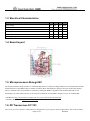
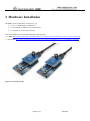
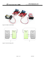
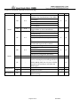
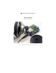
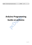
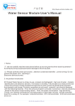
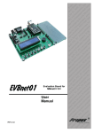
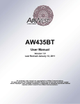
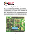
RFBee User Manual v1.1 Table of contents 1 2 3 4 5 Overview ........................................................................................................................................................................... 2 1.1 Licensing .............................................................................................................................................................. 2 1.2 Specifications........................................................................................................................................................ 2 1.3 Electrical Characteristics ...................................................................................................................................... 3 1.4 Board layout ......................................................................................................................................................... 3 1.5 Microprocessor-Atmega168 ................................................................................................................................. 3 1.6 RF Transceiver-CC1101 ....................................................................................................................................... 3 1.7 Pin layout .............................................................................................................................................................. 4 1.8 Schematic.............................................................................................................................................................. 4 Hardware Installation ........................................................................................................................................................ 6 Configuration .................................................................................................................................................................... 8 3.1 Version .................................................................................................................................................................. 8 3.2 Out of the box ...................................................................................................................................................... 8 3.3 AT Commands ...................................................................................................................................................... 8 3.3.1 AT Format: ................................................................................................................................................... 8 3.3.2 Supported commands: ................................................................................................................................ 9 3.3.3 Output format ............................................................................................................................................. 11 3.4 Broadcasting ....................................................................................................................................................... 11 How to update firmware .................................................................................................................................................. 12 Revision History ............................................................................................................................................................. 13 Page 1 of 13 8/27/2010 1 Overview The RFBee is a RF module providing easy and flexible wireless data transmission between devices. It is based on a AVR Atmega168 working as a fully functional Arduino connected via SPI to a TI CC1101 RF transceiver. Features: Range: Indoor/Urban: up to 50m; Outdoor line-of-sight: up to 120m; Receiver Sensitivity: -95dBm RF Data Transmission Rate: 4,800bps; 76,800bps Working Frequency : 868MHz & 915MHz Communication type: Point to Point, or Point to Multipoint. Easy-to-Use Serial Interface and rich extendable ports Easy-to-Use AT Command: Set working mode, Serial Baud Rate, etc. Open source Hardware and Firmware Socket compatible with the Xbee, so you can plug it into any Xbee socket as a quick replacement. Note: only the Rx,Tx, VCC, GND pins are identical to the Xbee. RFbee’s will not communicate with Xbee’s, so RFbee’s need to be used on both ends of the wireless connection. 1.1 Licensing This documentation is licensed under the Creative Commons Attribution-NonCommercial-ShareAlike License 3.0. Source code of the Atmega 168 firmware used in the RFBee is licensed under GPL/LGPL, see source code files for details. 1.2 Specifications Specification Value Microprocessor Atmega168 PCB size 24.38mmx32.94mmx0.8mm Indicators No Power supply 3.3v IO counts 9 ADC input 7(6 multiplexing with IO) Program interface USB Connectivity Socket compatible with XBee Communication Protocol Uart(TTL) Operating Frequency Band ISM 868MHz & 915MHz Outline Dimension 24.38mmx32.94mmx15mm Page 2 of 13 8/27/2010 1.3 Electrical Characteristics Specification Min Typ Max Unit Input voltage 3.0 3.3 3.6 VDC Transmit Current 34.5 mA Receive Current 18.1 mA Idle Current 5.2 mA Power-down Current <0.3 mA Operating Temperature -50 125 °C 1.4 Board layout 1.5 Microprocessor-Atmega168 The Atmega 168 has enough resources to control the RF transceiver while providing complete Uart communication and the default firmware of the RFBee offers a number of options. More importantly the Atmega 168 is one of the most popular MCU’s within the open source hardware community, making the RFBee compatible to the Arduino IDE and its vast knowledge pool. This enables the user to develop custom behavior for the RFBee using the easy to use Arduino IDE. >>Datasheet: http://www.atmel.com/dyn/resources/prod_documents/doc2545.pdf >>Arduino information: http://www.arduino.cc/ 1.6 RF Transceiver-CC1101 The CC1101 is a low-cost sub-1 GHz transceiver designed for very low-power wireless applications. The circuit is mainly Page 3 of 13 8/27/2010 intended for the ISM (Industrial, Scientific and Medical) and SRD (Short Range Device) frequency bands at 315, 433, 868, and 915MHz. The RFBee antenna and firmware are optimized for 868 and 915MHz. >>Datasheet: http://focus.ti.com/docs/prod/folders/print/cc1101.html 1.7 Pin layout PIN 3V3 TX RX PD4 !RESET PB1 PB0 PD7 !DTR GND PC3 PC2 PC1 VREF PC0 ADC7 PD5 PD6 PC5 PC4 # 1 2 3 4 5 6 7 8 9 10 11 12 13 14 15 16 17 18 19 20 Pad Type Supply input Output Input Input/Output Input Input/Output Input/Output Input/Output Input GND Input/Output Input/Output Input/Output Input Input/Output Input Input/Output Input/Output Input/Output Input/Output Description Vcc,+3.3v Uart Tx port Uart Rx port ATmega168 PD4 ATmega168 Reset port ATmega168 PB1 ATmega168 PB0 ATmega168 PD7 Used for programming the ATmega168 GND ATmega168 PC3 ATmega168 PC2 ATmega168 PC1 ATmega168 AREF port ATmega168 PC0 ATmega168 ADC7 ATmega168 PD5 ATmega168 PD6 ATmega168 PC5 ATmega168 PC4 Arduino Pin Number [1] 1(DIO) 0(DIO) 4(DIO) 9(DIO) 8(DIO) 7(DIO) 3(Analog input)/17(DIO) 2(Analog input)/16(DIO) 1(Analog input)/15(DIO) 0(Analog input)/14(DIO) 7(Analog input) 5(DIO) 6(DIO) 5(Analog input)/19(DIO) 4(Analog input)/18(DIO) Note: [1] Pin Number can be used in Arduino functions, like pinMode(),digitalWrite(),analogRead(),etc.. Page 4 of 13 8/27/2010 1.8 Schematic Page 5 of 13 8/27/2010 2 Hardware Installation The RFBee can be connected in various ways, e.g.: to a PC via USB using a UartSB device. to a Seeeduino (or Arduino) via an XbeeShield to any other device having a Uart port Note: the UartSB device and the XbeeShield are sold separately. >> UartSB: http://www.seeedstudio.com/depot/uartsb-v22-a-much-more-powerful-usb-to-serial-converter-p-495.html >> XbeeShield: http://www.seeedstudio.com/depot/xbee%C3%82%C2%AE-shield-v11-by-seeedstudio-p-419.html Figure 1: USB using UartSB Page 6 of 13 8/27/2010 Figure 2: Seeduino via XbeeShield Figure 3: Any device using a Uart Page 7 of 13 8/27/2010 3 Configuration 3.1 Version This section documents the configuration of RFBee firmware version 1.1. You can check the version of your firmware by issuing the ATFV command. 3.2 Out of the box When powered on, RFBee will send “ok” through serial port at 9600 baud. The default operation mode is “Transceive“ and the default sender and receiver address is 0. If you have two RFBee’s, any data submitted to the serial port of RFBee A will be emitted by the serial port of RFBee B. 3.3 AT Commands The configuration of the RFBee can be modified using AT commands. At startup the RFBee is in data mode. To submit AT commands, the RFBee must be switched to command mode by sending three plus signs (“+++”). When the RFBee receives the three plus signs on the serial port it will respond with: “ok, starting command mode”. The RFBee is now in command mode until switched back to data mode (using ATO0 see below) or power reset. 3.3.1AT Format: AT + Comand(ASCII) + parameters (optional, character)+<CR> Where <CR> is Carriage Return which has binary value 13 (0x0D in Hex) . Example: +++ ATBD1<CR> ATBD<CR> ATO0<CR> - Go to command mode, the RFBee will return “ok, starting cmd mode” - Set Uart Baudrate of the RFBee to 19200, returns “ok” on success and otherwise “error”. - Get Uart Baudrate of the RFBee, returns “1” and “ok” on success and otherwise “error”. - Go to datamode, the RFBee will return “ok” and any data send afterwards will be transmitted again. Page 8 of 13 8/27/2010 3.3.2Supported commands: Command Parameter AC 0-2 MA 0-255 DA 0-255 PA 0-7 CF 0-5 Adressing RF Specification Default Type Address Check: determines whether the RFBee checks the incoming packet address against its own address or not. If broadcast is enabled both its own address and the broadcast 0 address will be considered valid. 0:No address check 1:Address check, no broadcast 2:Address check and broadcast My Address: set the RFBee’s own address. Destination Address: set address of the receiver Power Amplifier: Set RF transmitting power. 0:-30dBm 1:-20dBm 2:-15dBm 3:-10dBm 4:0dBm 5:5dBm 6:7dBm 7:10dBm Config: select radio config 0: 915 Mhz, 76,8 Kbps, 2-FSK 1: 915 Mhz, 4.8 Kbps, GFSK, sensitivity 2: 915 Mhz, 4.8 Kbps, GFSK, low current 3: 868 Mhz, 76,8 Kbps, 2-FSK 4: 868 Mhz, 4.8 Kbps, GFSK, sensitivity 5: 868 Mhz, 4.8 Kbps, GFSK, low current Page 9 of 13 0 r/w 0 r/w 0 r/w 7 r/w 0 r/w 8/27/2010 Supported commands continued from previous page: Command Parameter BD 0-3 TH 0-32 OF 0-3 MD 0-3 O 0 SL - Diagnostics FV HV - Miscelaneous RS - Serial Mode Specification Default Type BaudRate: Set Uart Baudrate of the RFBee. 0: 9600bps 0 1: 19200bps 2: 38400bps 3: 115200bps Threshold: Set threshold in bytes that will 1 trigger RFBee to start transmission. Output format (see also section below) 0: payload only 1: source, dest, payload 0 2: payload len, source, dest, payload, rssi, lqi 3: same as 2, but all except for payload as decimal and separated by comma's Mode: Set working mode of the RFBee. 0:transceive 1:transmit only 0 2:receive only 3:lowpower (using Wake-On-Radio) Online: return to data mode Sleep: Put the RFBee to sleep to reduce power consumption, the Atmega will be in SLEEP_MODE_IDLE, the CC1101 in SPWD, activity on the serial port will wake the RFBee again. Firmware version 1.1 Hardware version <x>.<y> Restore: restore the configuration to default settings. Page 10 of 13 8/27/2010 r/w r/w r/w r/w w w r r w 3.3.3 Output format Using ATOF it is possible to change the output format of data packets received. ATOF set to 0: Payload ATOF set to 1: Source address (1 byte) Destination address (1 byte) Payload ATOF set to 2: Source address (1 byte) Destination address (1byte) Payload length (1 byte) Payload RSSI (1 byte) LQI (1 byte) ATOF set to 3: As ATOF2, but now all byte values (except Payload) displayed as decimal and all fields separated by comma’s. RSSI: Received Signal Strength Indicator. One byte signed data, unit dBm. LQI: Link quality indicator. One byte data, see CC1101 datasheet for details. 3.4 Broadcasting When every RFBee has it’s a unique address assigned (e.g. 1,2,3 and 4 if you have 4 RFBees) there are two ways to let all RFBee’s receive the same packets: 1. Set ATAC to 0: this will disable address checking and all RFBee’s will receive all packets sent. Downside of this is that any “private” communication between e.g. 2 and 3 will always show up at 1 and 4. 2. Set ATAC to 2: this will enable address checking including broadcasts. This will enable private communication between RFBee’s (e.g. packets between 2 and 3 will not show up at 1 and 4). The RFBee sending the broadcast must set the destination address to 0. Packets with destination address 0 will be received by all four RFBee’s. Page 11 of 13 8/27/2010 4 How to update firmware You can update the RFbee firmware using the Arduino IDE using the procedure below. This procedure assumes the use of UartSB as this is the easiest way to connect a RFBee to a PC, see the section on Hardware installation for different ways to connect. 1. Connect your RFBee to UartSB, move switches to XBee and 3.3v, then connect it to your computer through a USB cable. 2. Download the source code of the RFBee firmware into your Arduino sketch folder 3. Open the Arduino IDE and open the RFBee_vx_x project. Then select Tools->Board->Arduino Pro or Pro Mini (3.3v, 8MHz) w/ATmega168. Choose the correct serial port from the Tools menu. You can now upload your RFBee firmware. 4. Reapply the configuration changes in the RFBee if they got lost during the update. 5. You could add or modify the firmware upon your demands, as the RFBee is able to work standalone as an Arduino. >>RFBee firmware: http://code.google.com/p/rfbee/downloads/list Page 12 of 13 8/27/2010 5 Revision History Rev. Descriptions V1.0 Initial design, by Icing 2010/03/05 V1.01 Modify AT command DR and MD specifications, by Icing 2010/03/15 V1.02 Correct AC parameter, and firmware update process, by Icing 2010/05/01 V1.1 Major rework due to V1.1 firmware, by Hans and Icing 2010/08/27 Page 13 of 13 Release date 8/27/2010