1
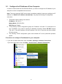
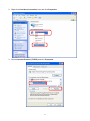
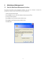
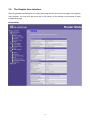
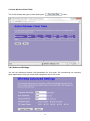
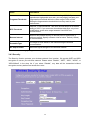
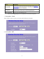
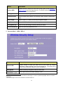
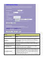
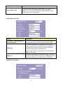
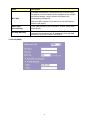
LevelOne User Manual WBR-6802 150Mbps Wireless Travel Router Ver. 1.0 Safety FCC WARNING This equipment may generate or use radio frequency energy. Changes or modifications to this equipment may cause harmful interference unless the modifications are expressly approved in the instruction manual. The user could lose the authority to operate this equipment if an unauthorized change or modification is made. This equipment has been tested and found to comply with the limits for a Class B digital device, pursuant to Part 15 of the FCC Rules. These limits are designed to provide reasonable protection against harmful interference in a residential installation. This equipment generates, uses, and can radiate radio frequency energy and, if not installed and used in accordance with the instructions, may cause harmful interference to radio communications. However, there is no guarantee that interference will not occur in a particular installation. If this equipment does cause harmful interference to radio or television reception, which can be determined by turning the equipment off and on, the user is encouraged to try to correct the interference by one or more of the following measures: 1) Reorient or relocate the receiving antenna. 2) Increase the separation between the equipment and receiver. 3) Connect the equipment into an outlet on a circuit different from that to which the receiver is connected. 4) Consult the dealer or an experienced radio/TV technician for help. CE Declaration of conformity This equipment complies with the requirements relating to electromagnetic compatibility, EN 55022 class B for ITE, the essential protection requirement of Council Directive 89/336/EEC on the approximation of the laws of the Member States relating to electromagnetic compatibility. CE Marking Warning Hereby, Digital Data Communications, declares that this product (Model-no. WBR-6802) is in compliance with the essential requirements and other relevant provisions of Directive 1999/5/EC. The CE-Declaration of Conformity can be downloaded at: http://www.levelone.eu/support.php 2 General Public License This product incorporates open source code into the software and therefore falls under the guidelines governed by the General Public License (GPL) agreement. Adhering to the GPL requirements, the open source code and open source license for the source code are available for free download at http://global.level1.com. If you would like a copy of the GPL or other open source code in this software on a physical CD medium, LevelOne (Digital Data Communications) offers to mail this CD to you upon request, for a price of US$9.99 plus the cost of shipping. 3 Contents 1 2 3 Introduction ······························································································ 5 1.1 Package Contents ·········································································· 5 1.2 Hardware installation steps ····························································· 6 1.3 The Front Panel ············································································· 7 1.4 The Rear Panel ·············································································· 8 Installation and Basic Configuration ···························································· 9 2.1 Operation Mode ············································································· 9 2.2 Connect This Router to Your Network ·············································· 9 2.3 Configure the IP Address of Your Computer ···································· 10 Web-Based Management ··········································································· 13 3.1 Start the Web-Based Management Interface ····································· 13 3.2 The Graphic User Interface ···························································· 14 3.3 Setup Wizard (Router mode and Client mode) ·································· 16 3.4 Wireless······················································································· 17 3.4.1 Basic Settings ·············································································· 17 3.4.2 Advanced Settings ········································································ 19 3.4.3 Security······················································································· 20 3.4.4 Access Control ············································································· 24 3.4.5 Wireless Site Survey (only in Client mode) ········································· 24 3.4.6 WPS Settings ··············································································· 25 3.5 TCP/IP Settings············································································· 27 3.5.1 LAN Interface Setup ······································································ 27 3.5.2 WAN Interface Setup (Router mode and Client mode) ·························· 28 3.6 Firewall Settings (Router mode and Client mode) ····························· 32 MAC Filtering ······················································································· 32 3.7 Management················································································· 33 3.7.1 Status ························································································· 33 3.7.2 Statistics······················································································ 33 3.7.3 Log ···························································································· 34 3.7.4 Upgrade Firmware ········································································ 35 3.7.5 Save/Reload Setting ······································································ 36 3.7.6 Password ···················································································· 36 3.7.7 Logout ························································································ 37 Appendix A: Product Specifications ·································································· 38 Appendix B: Glossary······················································································ 39 4 Default Settings IP Address 192.168.1.1 Password admin Wireless Mode Enable Wireless SSID LevelOne Security None 1 Introduction 1.1 Package Contents Open the box of the 150Mbps Wireless Travel Router and carefully unpack it. The box should contain the following items: WBR-6802 150Mbps Wireless Travel Router Power Adapter USB Cable CD-ROM with Manual and QIG Quick Installation Guide If any item is found missing or damaged, please contact your local reseller for replacement. 5 1.2 Hardware installation steps Decide where to place your Wireless Router You can place your Wireless Router on a desk or other flat surface. For optimal performance, place your Wireless Router in the center of your office (or your home) in a location that is away from any potential source of interference, such as a metal wall or microwave oven. This location must be close to power and network connection. Setup LAN connection Wired LAN connection: Connect an Ethernet cable from your computer’s Ethernet port to one of the LAN ports of the Wireless Router. Wireless LAN connection: Locate the WBR-6802 at a proper position to gain the best transmit performance. LAN WAN POWER PC/IP Device Power ADSL/Cable Modem Interne 3. Setup WAN connection Prepare an Ethernet cable for connecting this product to your cable/xDSL modem or Ethernet backbone. 4. Power on 6 1.3 The Front Panel The front panel of the Wireless Router: Name PWR WPS WLAN Status Indication Green Power on Dark Blink green one time Blink green WPS connecting Dark System stability Off The wireless function is disabled. Flashing The wireless function is enabled. Flashing fast Off WAN / LAN Power off System reboot On Flashing Sending or receiving data over wireless. There is no device linked to the corresponding port or the connection is dropping off. There are devices linked to the corresponding ports but no data transmitted or received. Sending or receiving data over corresponding port. 7 1.4 The Rear Panel The rear panel of the Wireless Router is shown below. LAN WAN POWER LAN: Through this port, you can connect the router to your PCs and the other Ethernet network devices. WAN: This WAN port is where you will connect the cable/DSL Modem, or Ethernet. DC IN: Plug the circle end of the power adapter firmly into the rear panel of the router, and put the other end into an electric service outlet, then the system is ready. WPS/Reset Button: Click this button for once it means to start PBC configuration method, in which users can easy setup WPS connection. If you push the button for more than 5 seconds and then release it, the system will return to factory default setting. In the meantime, system rewrites flash to default value and then system reboot. Approximately 60 seconds later, the whole system parameters have returned to factory default value. If the process has been interrupted by any reason(like power off), the system will fail. Before perform the process, please ensure a safe operating environment! Warning : Incomplete factory setting recovery procedure will cause the Wireless Router malfunction!If you are unfortunately in this situation, do not try to repair it by yourself. Consult your local distributor for help! 8 2 Installation and Basic Configuration This chapter will guide you steps by steps to install and configure the Wireless Router. We suggest you go over the whole chapter first and then do more advanced operation. 2.1 Operation Mode In this device, there are three modes for your selection: AP mode Router mode Client mode Different mode functions different. You can glide the slide switch on the left side of the device to the left hand side (AP mode), middle (Router mode) or right hand side (Client mode) to choose the mode you want. Before installation, please choose an operation mode first and then go on other configurations. 2.2 Connect This Router to Your Network Steps to build up the network: 1. Connect the phone line from the wall socket to the line-in port on the ADSL modem, or the coaxial cable to the line-in port on the cable modem. 2. A---Router Mode: Connect the ADSL or cable modem to the Ethernet WAN port on the back of the Wireless Router by using the UTP cable. B---AP Mode: Connect a router to one of the two ports on the back of this device by using the UTP cable. C---Client Mode: Skip step 1 and Go to steps 3 directly. 3. Plug-in the power adapter to the modem and turn on the power. Install the Ethernet card into the computer by referring to the User Guide that came with the card. 4. Connect the computer to the Wireless Router by using standard twisted-pair Ethernet cable from the computer’s Ethernet card to a 10/100Mbps Ethernet LAN port on the back of the Wireless Router. (In AP/Client mode both the ports can be used as LAN ports) 5. Plug-in the power adapter to the router and the other side to the wall outlet. 9 2.3 Configure the IP Address of Your Computer In order to communicate with this Wireless Router, you have to configure the IP address of your computer to make it compatible with the device. Note: The router supports DHCP server and it is enabled as default. Users who configure his IP address as “Obtain an IP address automatically” may skip the following IP configuration instruction. 1. The default network setting of the device: IP address: 192.168.1.1 Subnet Mask: 255.255.255.0 DHCP Server: Enable 2. In the following TCP/IP configuration guide, the IP address “192.168.1.2” is assumed to be your IP address if you want to specify IP addresses manually. Please DO NOT choose “192.168.1.1” as the IP address, for the IP address “192.168.1.1“has been set as the default IP for this device. 3. The following TCP/IP configuration guide uses windows XP as the presumed operation system. Procedures to configure IP addresses for your computer: 1. If you are in Classic Start menu view, click Start > Settings > Network Connections. If you are in Start menu view, click Start > Control Panel > Network Connections. 10 2. Right-click Local Area Connection item and click Properties. 3. Choose Internet Protocol (TCP/IP) and click Properties. 11 4. You may choose Obtain an IP address automatically (recommend) to get an IP address automatically. Or you can choose Use the following IP address to specify an IP address manually. Please click the OK button after your configuration. 12 3 Web-Based Management 3.1 Start the Web-Based Management Interface The device uses Web as the management interface. You can use a browser to access the management interface easily. Please follow the steps listed below. 1. Open the Internet Web browser. 2. Type 192.168.1.1 into the URL Web address location and press Enter. 3. The Login window appears. - Enter admin in the User Name location (default value). - Enter admin in the Password location (default value). - Click OK button. 13 3.2 The Graphic User Interface After the password authorization, the information page shows up as the home page of the graphic user interface. You may click the menu link on left column of the window to get access to each configuration page. Router Mode: 14 AP Mode: Client Mode: 15 3.3 Setup Wizard (Router mode and Client mode) If you are using the router for the first time, please follow the procedures of the setup wizard to do a step-by-step configuration. Note: The configurations in AP, Router and Client modes are almost the same. The following guide mainly introduces this device under the Router mode environment. Users want to do management in AP/Client mode please refer to the Router mode. The following instruction makes an overall introduction to the Setup Wizard 1. Click “Setup Wizard” on the left menu link, and then click the “Next” button to proceed. 2. Select a WAN access type for the router to connect to the Internet. And then click the “Finish” button. Or you can click “Back/Cancel” for any changing. You may get those parameters from your ISP. WAN Access Type: Static IP, DHCP Client and PPPoE. 16 3.4 Wireless 3.4.1 Basic Settings You can set up the configuration of your Wireless basic settings and monitor the Wireless Clients associate with your router. Items Information Disable Wireless LAN Interface Mark the checkbox to disable interface of Wireless LAN. Multiple AP button is to show and update the wireless settings The for Multiple APs. Click this button to do more configurations. SSID Service set identifier (SSID) for the name of the wireless network. Channel Width Select 20MHz or 40MHz as the wireless channel frequency. Control Sideband Upper, Lower Channel Number Select a channel (Auto, 1~11) for the wireless network of this device. Country It contains USA(FCC), Canada(IC), Europe(ETSI), Spain, France, Japan(MKK) for your selection. Broadcast SSID If you enable "Broadcast SSID", every wireless station located within the coverage of this wireless router can discover this wireless router easily. If you are building a public wireless network, enabling this feature is recommended. Disabling "Broadcast SSID" can be more safe. Associated Client Click "Show Active Clients" button, then an "Active Wireless Client Table" will pop up. You can see the status of all active wireless stations that are connecting to the access point. 17 * Please click on the Apply Changes button or the Reset button at the bottom to save/reset the configurations. 1. Multiple APs This is the window that pops up after clicking the button. Click “Enable” to activate this AP, and then click the button “Show”, “Active Wireless Client Table – AP1” window pops up as the following: 18 2. Active Wireless Client Table This is the window that pops up after clicking the button. 3.4.2 Advanced Settings You can set advanced wireless LAN parameters for this router. We recommend not changing these parameters unless you know what changes will be on this router. 19 Items Information Fragment Threshold This value should remain at its default setting of 2346. If you experience a high packet error rate, you may slightly increase your fragmentation threshold within the value range of 256 to 2346. Setting the fragmentation threshold too low may result in poor performance. RTS Threshold Request To Send threshold. This value should remain at its default setting of 2347. If you encounter inconsistent data flow, only minor modifications to the value range between 0 and 2347 are recommended. Beacon Interval Beacons are packets sent by an access point to synchronize a wireless network. Specify a beacon interval value. Default (100ms) is recommended. Preamble Type The length of CRC blocks in the frames during the wireless communication. RF Output Power Select the signal strength for the wireless network. * Please click on the Apply Changes button or the Reset button at the bottom to save/reset the configurations. 3.4.3 Security The Security function protects your wireless network from invasion. We provide WEP and WPA encryption to secure your wireless network. Please select “Disable”, “WEP”, “WPA”, “WPA2”, or “WPA2-Mixed” in the drop list. If you select “Disable”, any data will be transmitted without encryption and any station can access the router. 20 Items Information Select SSID Please choose a SSID you have set for this router in the Wireless > Basic Settings from the drop-down list. The SSID will be shown on the wireless network for recognizing. Encryption There are 5 modes for you to select: Disable, WEP, WPA, WPA2, and WPA2-Mixed. Please refer to the following description. Show Password Select to show the password or not. * Please click on the Apply Changes button or the Reset button to save/reset the configurations. 1. Security Mode – Disable Select “Disable” means to access your wireless network without any encryption. 2. Security Mode -- WEP 21 Items Information Select SSID Please choose a SSID you have set for this router in the Wireless > Basic Settings from the drop-down list. The SSID will be shown on the wireless network for recognizing. Encryption Select a security encryption mode for this router. Authentication There provide three options for selecting: Open System, Shared Key, Auto. Key Length Select “64-bit” or “128-bit” as the key encryption length. Key Format Select “ASCII 1” or “Hex 2” to setup the key value. Encryption Key Enter the key according to the key format you select. Show Password Select to show the password or not. * Please click on the Apply Changes button or the Reset button to save/reset the configurations. 3. Security Mode – WPA / WPA 2 Items Information Select SSID Please choose a SSID you have set for this router by clicking “Wireless > Basic Settings” from the drop-down list. The SSID will be shown on the wireless network for your recognition. Encryption Select a security encryption mode for this router. WPA/WPA2 Cipher WPA Cipher Suite: the default setting is TKIP. 1 ASCII (American Standard Code for Information Interchange) is a code for representing English letters as numbers from 0-127. 2 Hexadecimal digits consist of the numbers 0-9 and the letters A-F. 22 Suite WPA2 Cipher Suite: the defaulting setting is AES Pre-Shared Key Format To decide the format, select “Passphrase” or “Hex” in the drop list. Pre-Shared Key Enter the “Pre-shared Key” according to the pre-shared key format you select. This is the shared secret between AP and STA. This field must be filled with character longer than 8 and less than 64 lengths. Show Password Select to show the password or not. * Please click on the Apply Changes button or the Reset button to save/reset the configurations. 4. Security Mode – WPA2-Mixed Items Information Select SSID Please choose a SSID you have set for this router by clicking “Wireless > Basic Settings” from the drop-down list. The SSID will be shown on the wireless network for your recognition. Encryption Select a security encryption mode for this router. WPA / WPA2 Cipher Suite The Cipher Suite is mixed (TKIP and AES). Pre-Shared Key Format To decide the format, select “Passphrase” or “Hex” in the drop list. Pre-Shared Key Enter the “Pre-shared Key” according to the pre-shared key format you select. This field must be filled with character longer than 8 and less than 64 lengths. Show Password Select to show the password or not. * Please click on the Apply Changes button or the Reset button to save/reset the configurations. 23 3.4.4 Access Control To restrict the station access authentication of the clients, you can set up the control list in this page. Items Information Wireless Access Control Mode Click the drop list to choose the access control mode. You may select “Allow listed” to give those MAC addresses access to this device or select “Deny Listed” to ban it or select “Disable”. MAC Address & Comment Fill in the MAC address that you wish to control, and give a definition to it. Current Access Control list List the MAC Access Control settings you have added before. Click on the list to change configuration. To Delete the station on the list, mark the check box in the select item and click the “Delete Selected”. If you want to delete all stations on the list, click “Delete All” to remove all of them. * Please click on the Apply Changes button or the Reset button to save/reset the configurations. 3.4.5 Wireless Site Survey (only in Client mode) If you are under the Client mode, click Wireless > Wireless Site Survey in the menu links to display the screen as shown below. This page shows the available wireless network information. When you use this device as a client station (STA), you may connect to other AP or Router. Select one of the networks existing in the list of the site survey table and click “Connect” then your device can share the same 24 network with others successfully. Click the “Refresh” button can scan nearby Router and AP again. 3.4.6 WPS Settings The primary goal of Wi-Fi Protected Setup (Wi-Fi Simple Configuration) is to simplify the security setup and management of Wi-Fi networks. This router supports the configuration setup using PIN configuration method or PBC configuration method through an internal or external registrar. 25 Items Information Disable WPS Click this checkbox to undo WPS. WPS Status You cannot manually select the items here. The WPS Status will change from “UnConfigured” to “Configured” after you enable WPS function and setup a wireless security key for this device. Self-PIN Number If you use this device as a client, you can use this code when trying to connect this device to other AP by using the PIN method. Push Button Communication (PBC) method uses a simple action of pushing a button on both the AP and the new STA to reach the function Push Button Configuration of easy setup WPS connection. You can simply click the button in this GUI page or click the WPS button under the case of the router. After click on the button, please run the client’s WPS and push the PBC button within 2 minutes. Current Key Info This field displays the current key information you configured. Personal Identification Number (PIN) method. Users have to fill in the Client PIN Number PIN code of enrollee device and click the button to make communication between the AP and the enrollee device. After click on the button, please run the client’s WPS and push the PIN button within 2 minutes. *Please click on the Apply Changes button or the Reset button at the bottom to save/reset the configurations. If you are under the Client mode, the interface is different. Click Wireless > WPS in the menu links to display the screen as shown below. In this page you can connect your device to other networks by using PIN or PBC methods . 26 Items Information Disable WPS Mark to disable the WPS, and clear to enable. Self-PIN Number If you use this device as a client, you can use this code when trying to connect this device to other AP by using the PIN method. After the AP or router you share has fill in your self-pin number and click the PIN Configuration button in this GUI page at this moment you can click the minutes to establish the connection. Push Button Configuration 3.5 button in 2 button (or the WPS You can simply click the button) together with the AP or router you want share in 2 minutes for connection. TCP/IP Settings 3.5.1 LAN Interface Setup To set up the configuration of LAN interface, private IP of your router LAN port and subnet mask for your LAN segment. Items Information IP Address The IP of your Router LAN port (default 192.168.1.1). Subnet Mask Subnet Mask of you LAN (default 255.255.255.0). All devices on the network must have the same subnet mask to communicate on the network. 27 Default Gateway DHCP Client Range Enter the “IP Address” of the router in your network. DHCP stands for Dynamic Host Configuration Protocol. It is a protocol for assigning dynamic IP addresses “automatically”. This field asks you to specify the DHCP Client IP address range (default 100~200). You can also click the “Show Client” button to list those connected DHCP clients. Note: in Router/Client mode, DHCP Server default setting is enabled, however in AP mode, DHCP Server default setting is disabled. * Please click on the Apply Changes button or the Reset button at the bottom to save/reset the configurations. Active DHCP Client List This is the window that pops up after clicking the button. It shows the information of IP address, MAC address and expire time of the DHCP clients that have connected with this device. 3.5.2 WAN Interface Setup (Router mode and Client mode) This page allows users to configure those parameters for connecting to Internet. You may select the Internet connection type from the drop list besides “WAN Access Type” and configure the parameters for each mode. There are three modes for your selection: Static, DHCP and PPPoE. 28 Items Information WAN Access Type Select the mode to access the WAN as Static, DHCP Client or PPPoE. MTU Size To Enable the Maximum Transmission Unit of router setup. Any packet over this number will be chopped up into suitable size before sending. Larger number will enhance the transmission performance. Enter the MTU number in the blank to set the limitation. Attain DNS Automatically If your DNS provided by ISP is dynamic, choose “Attain DNS automatically. Set DNS Manually Clone MAC Address To specify the Domain Name System (DNS). The DNS server translates domain names into IP addresses. Enter the DNS provided by your ISP in DNS 1 and DNS 2. There are two ways to clone MAC address. One way is directory input MAC address in text box. Maybe you need to save the MAC Address, you can click 'Manual Add' button and add it to “History MAC Table” for easily backup; another is click 'MAC Clone' button, then it will copy the MAC address from your network card in the computer. Note: The 'History MAC Table' can save maximum three MAC 29 Addresses. History MAC Table To Delete the MAC Address you add before, mark the check box in the select item on the right hand and click the “Delete Selected”. If you want to delete all the MAC Addresses, click “Delete All” to remove all of them. * Please click on the Apply Changes button or the Reset button at the bottom to save/reset the configurations. 1. Static Mode (fixed IP) Items Information IP Address, Subnet Mask and Default Gateway Fill in the IP address, Subnet Mask and Default Gateway that provided by your Internet Service Provider (ISP). MTU Size To Enable the Maximum Transmission Unit of router setup. Any packet over this number will be chopped up into suitable size before sending. Larger number will enhance the transmission performance. Enter the MTU number in the blank to set the limitation (default 1500 bytes). DNS 1~2 To specify the Domain Name System (DNS). The DNS server translates domain names into IP addresses. Enter the DNS provided by your ISP in DNS 1 and DNS 2. 2. DHCP (Auto Config) 30 Items Information MTU Size To Enable the Maximum Transmission Unit of Router setup. Any packet over this number will be chopped up into suitable size before sending. Larger number will enhance the transmission performance. Enter your MTU number in the text-box to set the limitation (default 1492 bytes). Attain DNS Automatically If your DNS provide by ISP is dynamic, choose “Attain DNS automatically. Set DNS Manually To specify the Domain Name System (DNS). The DNS server translates domain names into IP addresses. Enter the DNS provided by your ISP in DNS 1 and DNS 2. 3. PPPoE (ADSL) 31 Items Information User Name&Password Fill in the User Name and password that provided by your ISP. MTU Size To Enable the Maximum Transmission Unit of router setup. Any packet over this number will be chopped up into suitable size before sending. Larger number will enhance the transmission performance. Enter your MTU number in the text-box to set the limitation (default 1452 bytes). Attain DNS Automatically If your DNS provided by ISP is dynamic, choose “Attain DNS automatically. Set DNS Manually To specify the Domain Name System (DNS). The DNS server translates domain names into IP addresses. Enter the DNS provided by your ISP in DNS 1 and DNS 2. 3.6 Firewall Settings (Router mode and Client mode) MAC Filtering The Wireless Router could filter the outgoing packets for security or management consideration. 32 Items Information Enable MAC Filtering Mark to enable the configuration, and clear to disable. MAC Address Fill in the MAC address of wireless stations you want to forbid to access the Internet through the Gateway. Comment Input any text to describe this mapping. Current Filter Table Lists the MAC Filter Settings you have added before. To delete the settings on the list, click the check box in the select item and click the “Delete Selected”. If you want to delete all the MAC addresses, click “Delete All” to remove all of them. Please click on the Apply Changes button or the Reset button at the bottom to save/reset the configurations. 3.7 Management 3.7.1 Status This information page shows the current status and basic settings of this device. You could check if the parameters match your configuration. 3.7.2 Statistics This page shows users the information of data transfer, and monitors the status of this router 33 including receiving and sending packets. To see the latest report, click button. 3.7.3 Log This System Log page shows the information of the current activities on the router. To enable system log function: 1. Mark the “Enable Log” checkbox. 2. To see all information of the system, select the “system all” checkbox. To see wireless information only, select the “wireless” checkbox. 3. Click the button to activate. You could also click the refresh the log information or click the button to clean the log table. 34 button to 3.7.4 Upgrade Firmware Sometimes a new firmware may be issued to upgrade the system of this device. You could upgrade the firmware you got in this page. To upgrade the firmware, please click the button, locate the firmware in your computer and then click the 35 button to execute. 3.7.5 Save/Reload Setting The Save/Reload Setting page allows users to save and upload the configuration settings of the device or restore the factory default configuration. Items Information Save Settings to File Click the settings. button to save the currently configure Click Load Settings from File Reset Settings to Default to select the file that you save, and then to start to update the system configuration click settings. Please wait until it is complete. Click to start to load default settings. 3.7.6 Password To set up the Administrator Account information, enter the Username, New password, and reenter the password on the text box. Don’t forget to click the 36 to save the configuration. 3.7.7 Logout Click Apply Change then you will save the settings and log off the management interface. 37 Appendix A: Product Specifications Standard IEEE 802.11n, IEEE 802.11g, IEEE 802.11b, IEEE 802.3, IEEE 802.3u Interface LAN: One 10/100Mbps RJ-45 port WAN: One 10/100Mbps RJ-45 port One WPS/RESET button One slide switch to control AP/Router/Client mode One USB DC JACK Antenna Internal Antenna WAN Connection Ethernet 10/100 Mbps Cable Connections RJ-45 (10BASE-T): Category 3,4,5 UTP RJ-45 (100BASE-TX): Category 5 UTP Transmission Mode Auto-Negotiation (Full-duplex, Half-duplex) Security 64/128-bit WEP, WPA, WPA2, WPA2-Mixed Network Data Rate Receiver Sensitivity 802.11b: 1,2,5.5, and 11Mbps 802.11g: 6,9,12,18,24,36,48 and 54Mbps 802.11n: up to 150Mbps 802.11n Typical -68 dBm 802.11g Typical -73 dBm 802.11b Typical -84 dBm Transmit Power 16dBm typically @ 802.11b 14dBm typically @ 802.11g 13dBm typically @ 802.11n LED indications 1*WAN, 1*LAN, 1*WLAN, 1*WPS, 1*PWR Channel Range Coverage Temperature Humidity Certification USA 11, Europe 13, Japan 14 Indoor 35~100 meters Outdoor 100~300 meters Operating: 0°C ~ 40°C (32°~104°F) Storage: -20°C ~ 70°C (-4°~158°F) Operating: 10% ~ 90% RH, non-condensing Storage: 5%~90% RH, non-condensing FCC, CE, VCCI Class B 38 Appendix B: Glossary 802.11b - The 802.11b standard specifies a wireless networking at 11 Mbps using direct-sequence spread-spectrum (DSSS) technology and operating in the unlicensed radio spectrum at 2.4GHz, and WEP encryption for security. 802.11b networks are also referred to as Wi-Fi networks. 802.11g - specification for wireless networking at 54 Mbps using direct-sequence spread-spectrum (DSSS) technology, using OFDM modulation and operating in the unlicensed radio spectrum at 2.4GHz, and backward compatibility with IEEE 802.11b devices, and WEP encryption for security. 802.11n - 802.11n builds upon previous 802.11 standards by adding MIMO (multiple-input multiple-output). MIMO uses multiple transmitter and receiver antennas to allow for increased data throughput via spatial multiplexing and increased range by exploiting the spatial diversity, perhaps through coding schemes like Alamouti coding. The Enhanced Wireless Consortium (EWC) was formed to help accelerate the IEEE 802.11n development process and promote a technology specification for interoperability of next-generation wireless local area networking (WLAN) products. DHCP (Dynamic Host Configuration Protocol) - A protocol that automatically configure the TCP/IP parameters for the all the PC(s) that are connected to a DHCP server DNS (Domain Name System) – An Internet Service that translates the names of websites into IP addresses. Domain Name - A descriptive name for an address or group of addresses on the Internet. DSL (Digital Subscriber Line) - A technology that allows data to be sent or received over existing traditional phone lines. ISP (Internet Service Provider) - A company that provides access to the Internet. MTU (Maximum Transmission Unit) - The size in bytes of the largest packet that can be transmitted. NAT (Network Address Translation) - NAT technology translates IP addresses of a local area network to a different IP address for the Internet. PPPoE (Point to Point Protocol over Ethernet) - PPPoE is a protocol for connecting remote hosts to the Internet over an always-on connection by simulating a dial-up connection. SSID - A Service Set Identification is a thirty-two character (maximum) alphanumeric key identifying a wireless local area network. For the wireless devices in a network to communicate with each other, all devices must be configured with the same SSID. This is typically the configuration parameter for a wireless PC card. It corresponds to the ESSID in the wireless Access Point and to the wireless network name. WEP (Wired Equivalent Privacy) - A data privacy mechanism based on a 64-bit or 128-bit or 152-bit shared key algorithm, as described in the IEEE 802.11 standard. Wi-Fi - A trade name for the 802.11b wireless networking standard, given by the Wireless Ethernet Compatibility Alliance (WECA, see http://www.wi-fi.net), an industry standards group promoting interoperability among 802.11b devices. WLAN (Wireless Local Area Network) - A group of computers and associated devices communicate with each other wirelessly, which network serving users are limited in a local area. 40