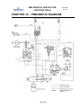
1
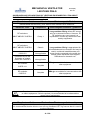
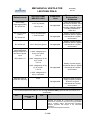
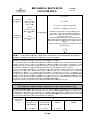
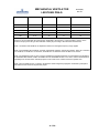
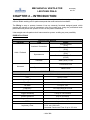
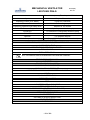
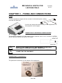
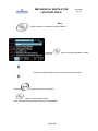
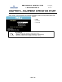
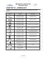
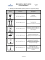
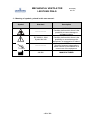
MECHANICAL VENTILATOR PR4 - g R 04-04 (44) REV. 04 GMP CERTIFICATE NBR ISO 9001:2008 EN ISO 13485:2003 + AC 2009 MECHANICAL VENTILATOR LEISTUNG PR4-G - 2 of 50 - R 04-04(44) Rev. 04 MECHANICAL VENTILATOR LEISTUNG PR4-G Manufactured by: LEISTUNG EQUIPAMENTOS LTDA. 202, Joao RopelattoSt City: Jaragua do Sul – Santa Catarina District: Nereu Ramos Postal code 89265-300 Phone: 55 (47) 3371-2741 Fax: 55 (47) 3371-9267 VAT No. 04.187.384/0001-54 I.E: 254.417.108 Op. Auth.: GHL3983MX9H2 GMP Certificate Standard EN ISO 13485:2003 + AC 2009 NBR ISO 9001:2008 Website: www.leistungbrasil.com E-mail: [email protected] Legal Responsible: Marcelo Javier Fernandez TechnicalResponsible: Eng. Fernando Alves Negrão CREA/SC 077160-5 ANVISA registry: Technical Name:Pressure and Volume Lung Ventilator Commercial Name: Lung Ventilator Leistung PR4-g ANVISA Registry No.:80203470005 - 3 of 50 - R 04-04(44) Rev. 04 MECHANICAL VENTILATOR LEISTUNG PR4-G R 04-04(44) Rev. 04 SUMMARY SUMMARY ................................................................................................................................................. 4 GUIDELINES AND DECLARATIONS OF LEISTUNG EQUIPAMENTOS LTDA ABOUT ELECTROMAGNETIC COMPATIBILITY (EMC) .................................................................................... 6 CHAPTER 1 – PRESENTATION ............................................................................................................. 10 WARNINGS, CAUTIONS AND NOTES ............................................................................................... 12 CHAPTER 2 – INTRODUCTION ............................................................................................................. 14 ESPECIFICATIONS ............................................................................................................................. 14 CHAPTER 3 – FIXING AND CONNECTIONS ........................................................................................ 16 FIXING.................................................................................................................................................. 16 CONNECTING TO EXTERNAL POWER SOURCE ............................................................................. 16 VERIFY IF THE CONNECTION OF THE EQUIPMENT IS PROPERLY PERFORMED TO ENSURE A CORRECT OPERATION. ...................................................................................................... 16 VERIFY IF THE JACK IS COINCIDENT WITH THE PLUG BEFORE CONNECTING THE EQUIPMENT. ................................................................................................................................................ 16 CONNECTING TO GAS SUPPLY ........................................................................................................ 16 BREATHING CIRCUIT ......................................................................................................................... 18 CHAPTER 4 – INDICATORS AND CONTROLS .................................................................................... 19 FRONT PANEL .................................................................................................................................... 19 1- LCD 7”DISPLAY ........................................................................................................................... 19 2- ALARMS ....................................................................................................................................... 19 3- DIRECT ACCESS FUNCTIONS................................................................................................... 19 4- CONTROLS AREA ....................................................................................................................... 19 ALARMS ............................................................................................................................................... 21 DIRECT ACCESS FUNCTIONS .......................................................................................................... 22 CONTROLS AREA ............................................................................................................................... 23 CHAPTER 5 – EQUIPMENT OPERATION START ................................................................................ 26 CHAPTER 6 – VENTILATION MODES................................................................................................... 27 VENTILATION MODES–ADULT AND PEDIATRIC ............................................................................. 27 VCV – VOLUME CONTROLLED VENTILATION .................................................................................... 27 INSPIRATORY TIME.................................................................................................................................... 27 BREATHING FREQUENCY ........................................................................................................................ 28 TIDAL VOLUME ............................................................................................................................................ 28 PEEP .............................................................................................................................................................. 28 SENSIBILITY ................................................................................................................................................. 29 PCV – PRESSURE CONTROLLED VENTILATION............................................................................. 29 RISE TIME ..................................................................................................................................................... 30 CONTROLLED PRESSURE ....................................................................................................................... 31 PSV/CPAP – PRESSURE SUPPORT VENTILATION OR CONTINUOUS POSITIVE PRESSURE ... 31 PRESSURE SUPPORT ............................................................................................................................... 32 SIMV (VCV) + PSV - SYNCHRONIZED INTERMITENT MANDATORY VENTILATION BY PRESSURE WITH PRESSURE SUPPORT ............................................................................................................. 32 BACKUP VENTILATION .............................................................................................................................. 33 VENTILATION MODE .................................................................................................................................. 34 APNEA TIME ................................................................................................................................................. 34 CYCLING VARIABLES ................................................................................................................................ 34 - 4 of 50 - MECHANICAL VENTILATOR LEISTUNG PR4-G R 04-04(44) Rev. 04 PEEP .............................................................................................................................................................. 34 NEONATAL VENTILATION MODES ................................................................................................... 34 CONTINUOUS FLOW .................................................................................................................................. 35 NASAL CPAP – CONTINUOUS POSITIVE PRESSURE VENTILATION ............................................ 35 CHAPTER 7 – ALARMS.......................................................................................................................... 36 COLORS AND MEANINGS OF GRAPHICAL INDICATORS ................................................................ 36 HIGH PRIORITY ALARM CONDITION ..................................................................................................... 36 MAXIMUM INSPIRATORY PRESSURE ................................................................................................... 36 MINIMUM INSPIRATORY PRESSURE .................................................................................................... 36 APNEA ALARM ............................................................................................................................................. 37 INTERRUPTED CYCLE .............................................................................................................................. 37 OXYGEN LOW PRESSURE ....................................................................................................................... 37 MICROPROCESSOR .................................................................................................................................. 37 LOW PRIORITY ALARM CONDITION ...................................................................................................... 37 MAXIMUM TIDAL VOLUME ........................................................................................................................ 37 MINIMUM TIDAL VOLUME ......................................................................................................................... 37 MAXIMUM RESPIRATORY FREQUENCY .............................................................................................. 38 PEEP ALARM ................................................................................................................................................ 38 TESTE DE INTEGRIDADE DO SISTEMA DE ALARMES .................................................................... 39 CHAPTER 8 – EXHALATION VALVE ASSEMBLY ............................................................................... 40 CHAPTER 9 – CLEANING,DESINFECTION AND STERILIZATION ..................................................... 41 CHAPTER 10 – SYMBOLOGY ............................................................................................................... 43 3 – MEANING OF SYMBOLS, PRINTED IN THIS USER MANUAL: ................................................... 45 CHAPTER 11 – ACCESSORIES............................................................................................................. 46 CHAPTER 12 – PREVENTIVE MAINTENANCE .................................................................................... 47 CHAPTER 13 – PNEUMATIC DIAGRAM ............................................................................................... 48 CHAPTER 14 –RADFORDTABLE .......................................................................................................... 49 WARRANTY ............................................................................................................................................ 50 - 5 of 50 - MECHANICAL VENTILATOR LEISTUNG PR4-G R 04-04(44) Rev. 04 GUIDELINES AND DECLARATIONS OF LEISTUNG EQUIPAMENTOS LTDA ABOUT ELECTROMAGNETIC COMPATIBILITY (EMC) Manufacturer Guidance and Declarations – Electromagnetic Emission PR4-gis designated for use in electromagnetic ambience as specified bellow. It is recommended that the PR4-g user ensures it be utilized in such ambience. Electromagnetic ambience - guidelines Emission Tests Compliance Lung ventilator PR4-g utilizes RF energy only for its internal functions. However, its RF emissions are very low and it is improbable it causes any interference with nearby equipments. RF emissions ABNT NBR IEC CISPR11 Group 1 RF emissions ABNT NBR IEC CISPR11 Class A Harmonic emissions IEC 61000-3-2 Not applicable Emissions due to the fluctuation of voltage flicker IEC 61000-3-3 Not applicable RF emission CISPR 14-1 RF emission CISPR 15 Complies Complies Lung ventilator PR4-g is appropriated for all establishments but domestic and may be used in residential establishments and those directly connected to the public low voltage power distribution that supplies edifications for domestic use. PR4-gis not suitable for interconnection with other equipment. PR4-gis not suitable for interconnection with other equipment. Para In order to avoid RF interference, the PR4-g should not be used stacked on others equipment. If this is required, it is recommended to be observed the normal use of equipments. Manufacturer Guidance and Declaration – Electromagnetic Immunity PR4-g is intended for use in environment electromagnetic specified below. It is recommended that the client or user of Lung Ventilator LUFT2-g ensures that it is used in such environment. - 6 of 50 - MECHANICAL VENTILATOR LEISTUNG PR4-G Emission tests Test Level ABNT NBR IEC 60601 Electrostatic Discharges (ESD) ± 6 kV by contact IEC 61000-4-2 ± 8 kV by air Fast Transient Burst (“Burst”) ± 2 kV at power lines Not applicable ± 1kvat I/O lines IEC 61000-4-4 Surges ± 1 kV line(s) to line(s) IEC 61000-4-5 ± 2 kV line(s) to ground Power outage, short interruptions and voltage variations on the lines of power input < 5% Ut IEC 61000-4-11 Compliance Level R 04-04(44) Rev. 04 Electromagnetic Environment – Guidances Floors should be wood, concrete or ceramic. If the floors are covered with synthetic material, relative humidity should be at least 30%. Not applicable Quality of power supply should be that of a typical commercial or hospital environment. Not applicable Quality of power supply should be that of a typical commercial or hospital environment. (> 95% voltage drop of Ut) by 0.5 cycles. 40% Ut (60% voltage drop of Ut) by 5 cycles 70% Ut (30% voltage drop of Ut) by 25 cycles. < 5% Ut Not applicable Quality of power supply should be that of a typical commercial or hospital environment. (> 95% voltage drop of Ut) by 5 seconds. Magnetic fields at power line frequency 3A/m Not applicable Magnetic fields at power supply frequency should be that of a typical commercial or hospital environment. Manufacturer Guidance and Declaration – Electromagnetic Immunity The Lung Ventilator PR4-g is intended for use in environment electromagnetic specified below. It is recommended that the client or user of Lung Ventilator PR4-g ensures that it is used in such environment. Immunity tests Test level ABNT NBR IEC 60601 Compliance level Electromagnetic Environment – Guidances Portable and mobile RF communication equipments must not be used close to any part of the lung ventilator PR4-g, including cables, Recommended separation distance (equation with respect to the transmitter frequency. Recommended separation distance: - 7 of 50 - MECHAN M NICAL VENTILA V ATOR LEISTUNG G PR4-G R 04-04 4(44) Rev. 04 d= 1.16 6[P]½ RF Co onducted IEC 61000-46 6 3 Vrms o 80 150 kHz up to MHz out of th he bandsA ISM M d= 1.2 [ P ] ½ d= 1.2 2 [ P ] ½ 80 M MHz up to 800 MHz 10 Vrms o 80 150 kHz up to M MHz within ban ndsA ISM RF Radiated R IEC 61000-46 3 d= 2.3 3 [ P ] ½ 800 M MHz up to 2.5 GHz Not Applicable A 10 V/m 8 MHz up to 2.5 80 GHz Where P is the maximum nominal powe er output of transmitter,, in watts (W), according to transmitter manufacturerr, and d is the recommende ed separation distance, in meters (m). The field inte ensity established by RF tra ansmitter, as determined d byy electromagne etic inspection n on the localc should s be lesss than compliance level in ea ach frequencyy band d D. Interference may m occur arou und the equipment marked with this symbol: NOTE E1 At 80 0 MHz and 800 MHz applies the highest range of frequency. NOTE E2 This guidance ma ay be not applicable in all situations. The electrom magnetic pro opagation is affectted by absorrption and refflection of strructures, objects and peo ople. A The T bandwidth h ISM (Industrry, medical an nd scientific), between b 150 kHz and 80 M MHz are 6.765 5 MHz; 13.553 3 MHz to t 13.564 MHzz; 26.957 MHzz to 27.283 MHz and 40.66M MHz to 40.70M MHz. B The compliance e level in the bandwidth b ISM M between 15 50KHz and 80M MHz and in th he frequency range between n 80MH Hz to 2,5GHz, intends to reduce the prob bability of mob bile and porta able communiccation equipm ments to cause e interfe erence if they are inadverte ently brought to t the patient´´s environmen nt. For this rea ason, an addittional factor of 10/3 iss used to calcculate the reco ommended separation distance for transm mitter in range of frequency.. C The field intenssity establishe ed by fix tran nsmitters, like e base transcceiver station ns, telephone (cellular and d wirele ess), land mo obile radio, am mateur radio, AM and FM M transmitter and TV transsmitter, can´t be predicted d theore etically with accuracy. a To evaluate the e electromagn netic environm mental due to o RF fix tran nsmitters, it iss recom mmended to co onsider a loca al electromagn netic inspection. If the local field intensity where the Lu ung Ventilatorr PR4-g g is located exceeds e the above a applica able RF comp pliance level, the Lung Ve entilator PR4 4-g should be e obserrved in order to o verify the no ormal operatio on. If an unusu ual performancce is observed d, additional procedure p mayy be necessary, such h as reorienting g or replacem ment of Lung ventilator v PR4 4-g. D Abo ove the freque ency range of 150kHz, the fiield intensity should s be sma aller than (v1) V/m. Recomm mended sep paration diistance bettween portable and mob bile RF com mmunicatio on equipments and th he Lung Ve entilator PR R4-g The Lung L Ventila ator PR4-g iss intended fo or use in an electromagne etic environm ment in which h radiated RF F disturrbances are controlled. The T customerr or the userr of the Lung g Ventilatorr PR4-g can help prevent electrromagnetic interference by maintaining a minim mum distance e between p portable and d mobile RF F comm munications equipment e (tra ansmitters) and a the Lung Ventilator PR4-g P recom mmended belo ow, according g to the e maximum ou utput power of o the commu unications equ uipment. Rate ed maximum outp put power of transmitter W Separa ation distance according to frequency f of transmitter m 150 kH Hz to 80 MHz out of Bandwidtth ISM d= 1.16 [ P ] ½ 150 kHz up to o 8 MHz within 80 n b bandwidth ISM M d= 1.2 [ P ] ½ 5 - 8 of 50 Hz up to 80 MH 800 0 MHz d= 1.2 [ P ] ½ 800 MH Hz up to 2.5G GHz MECHANICAL VENTILATOR LEISTUNG PR4-G R 04-04(44) Rev. 04 d= 2.3 [ P ] ½ 0.01 0.11 0.12 0.12 0.23 0.1 0.36 0.37 0.37 0.72 1 1.16 1.2 1.2 2.3 10 3.68 3.79 3.79 7.27 100 11.67 12 12 23 For transmitters rated at a maximum output power not listed above, the recommended separation distance d in metres (m) can be estimated using the equation applicable to the frequency of the transmitter, where P is the maximum output power rating of the transmitter in watts (W) according to the transmitter manufacturer. NOTE 1 At 80 MHz and 800 MHz, the separation distance for the higher frequency range applies NOTE 2 At bandwidth ISM (Industrial, Scientific and Medical), between 150 kHz and 80 Mhz, there are 6.765 MHz to 6.795 MHz; 13.553 MHz to 13.567 MHz; 26.957MHz to 27.283 MHz and 40.66 MHz to 40,70 MHz. NOTE 3 An additional margin of 10/3 is used to calculate the separation distance recommended for transmitters in the bandwidth ISM between 150kHz and 80Mhz and the bandwidth 80 MHz to 2.5 GHz to reduce the interference probability from communication mobile equipment could cause if it be carried unwarned in patient area. NOTE 4 These guidelines may not apply in all situations. Electromagnetic propagation is affected by absorption and reflection from structures, objects and people. - 9 of 50 - MECHANICAL VENTILATOR LEISTUNG PR4-G R 04-04(44) Rev. 04 CHAPTER 1 – PRESENTATION In this User Manual, are presented the necessary information for the correct use of the Lung Ventilator PR4-g. The indications relating to enforcement and regulations, mentioned in this manual, is a guideline, the physician should adapt, as their criterion, the needs of patients. GENERAL MODEL ANVISA Registry MEDICAL DEVICE CLASSIFICATION OPERATION MODE Classification according to type against electrical shock (insulation). PR4-g No. 80203470005 CLASS III Continuous operating CLASS II Internally Energized Device Classification according to type of protection against electrical shock Level of protection against water penetration TYPE B IPX0 EQUIPMENT NOT SUITABLE FOR USE IN THE PRESENCE OF FLAMMABLE ANESTHETIC MIXTURE WITH AIR, OXYGEN OR NITROUS OXIDE. PHYSICAL CHARACTERISTICS PARAMETERS Value Dimensions (Ventilator) Height Width Depth Weight 150 mm 270 mm 230 mm 5.20 kg EXTERNAL ELECTRIC POWER SOURCE NOMINAL VOLTAGE 11.5 V up to 15 V NOMINAL CURRENT NOMINAL POWER INPUT FUSE 1.90A up to 1.5A 30 W (Max.) 2.5A/250V 20 mm SB SLOW REPLACE THE FUSE ONLY WITH OTHER WITH THE SAME CURRENT AND VOLTAGE SPECIFICATIONS. INTERNAL ELECTRIC POWER SOURCE 12 V Nominal Voltage Nominal Capacity Type Autonomy 2.2Ah VRLA (Sealed, does not emit gas) Battery Completely Minimum of 120 minutes - 10 of 50 - MECHANICAL VENTILATOR LEISTUNG PR4-G Capacity affected by temperature Auto-discharge 68ºF (20ºC) Charged 77ºF (25ºC) 104ºF (40ºC) 77ºF (25ºC) 32ºF (0ºC) 5ºF (-15ºC) Capacity after 3 months Capacity after 6 months Capacity after 12 months R 04-04(44) Rev. 04 autonomy 102% 100% 85% 65% 90% 80% 60% Maximum Discharge 48A (5s) Current77ºF (25ºC) Charge Floating 77ºF (25ºC) 13.6 – 13.8V / 1.25A (max). (Constant Voltage) Charging Time Vmin=10.5V 4 Hours (Battery Discharged) Maximum temperature 131ºF (55ºC) Internal fuses 2.5A 20 mm SB SPECIFICATIONS INFORMED BY BATTERY MANUFACTURER. THE INTERNAL BATTERY AND FUSE ARE NOT REPLACEABLE BY OPERATOR. THE SWITCHING FOR INTERNALLY BATTERY OCCURS AUTOMATICALLY WITHOUT THE NECESSITY OF EXTERNAL INTERVENTION, IT DOES NOT INTERFERES THE OPERATION OF THE EQUIPMENT OR THE INSPIRATORY PRESSURE AT OUTPUT PORT TO PATIENT ENVIRONMENTAL SPECIFICATIONS VALUES Operation 10ºC up to 35ºC Environment Temperature Storage – Transport 2ºC up to 40ºC (*) 10% up to 95% Non Operation condensable Relative Humidity 0% up to 95% Non Storage – Transport condensable Operation 66 – 100 kPa Atmospheric Pressure Storage – Transport 66 – 100 kPa PNEUMATIC INPUTS OXYGEN Input DISS 9/16” – 18 PRESSURE From2.8up to6 kg/cm2 FLOW Up to 150 l/min USE ONLY MEDICAL GRADE GAS. THE MEASURE OF VOLUME AND PRESSURE IS STANDARDIZED BY BAROMETRIC PRESSURE AT SEA LEVEL, BODY TEMPERATURE AND WATER VAPOR SATURATE (BTPS) AND THEY ARE ADJUSTED IN FUNCTION OF ALTITUDE. (*) The storage of the lung ventilator for long periods at temperature greater than 27ºc, or without electrical connection for periods greater than 2 months, may affect the internally battery life. - 11 of 50 - MECHANICAL VENTILATOR LEISTUNG PR4-G R 04-04(44) Rev. 04 WARNINGS, CAUTIONS AND NOTES WARNINGS Constant attention of specialized personnel is required when patient is connected. Operation problems require immediate corrective actions. The professional in charge of its use should, using your own criterion and knowledge, apply the equipment at patient needs. Do not use this equipment in the presence of flammable anesthetic gas mixture, explosion or fire risk. Do not use anti-static tubes or electrical conductor in the patient circuit. Do not sterilize the equipment with ethylene oxide. There is a high probability to occur irreversible damage in the ventilator components. The equipment may be affected by High Frequency Electromagnetic Interference (as cellular, wireless telephone, defibrillators, electro-surgical knifes, magnetic resonance, etc.). Use the tables from Guidance of Electromagnetic Emission and Immunity to determine the correctly separation distances. The utilization of accessories and cables that are not specified by LeistungEquipamentosLtda as replacement parts for internal components may result in Emission increase or Immunity reduction of PR4-g. Before first utilization and after utilization in each patient, it is necessary clean the ventilator. To sterilize the accessories, follow the instructions on chapter 9. When the equipment is not in utilization, close de O2 cylinder as a safe procedure. CAUTIONS During the warranty period, the stay or movement of equipment should be performed with the original packaging, with its internal correspondent protection, otherwise will result in loss of warranty. Never sterilize the ventilator, the internal components is not compatible with sterilization technique. Follow the instructions at chapter 9 for equipment cleaning and accessories sterilization. Never operate the equipment exposed to direct heat or sunlight. Never cover or place the equipment in order to block the air entry for cooling. To ensure electrical protections and avoid risk of fire, never change the fuses. If the equipment does not work, contact the Authorized Technical Support. - 12 of 50 - MECHANICAL VENTILATOR LEISTUNG PR4-G R 04-04(44) Rev. 04 The improper replacement of the fuses nullifies warranty and represents a risk for the equipment operation, operator and patient safety. NOTES The ventilator is a medical device that has to be operated by qualified and trained people, supervised by a physician. When the Lung Ventilator PR4-g is in use, an alternative mean of ventilation should always be available. The PR4-g is produced with recyclable materials and should not be thrown into common landfills because it contains toxic materials to nature, for this, contact an authorized dealer. Electric Diagrams, Circuitry Diagrams, component list, repair instructions and training can be provided by LeistungEquipamentosLtda, by agreement between the parts. LeistungEquipamentos Ltda. is a company of continuous improvement in its products and technical specifications can change without notice. - 13 of 50 - MECHANICAL VENTILATOR LEISTUNG PR4-G R 04-04(44) Rev. 04 CHAPTER 2 – INTRODUCTION The Lung Ventilator PR4-g is micro-controlled and developed within the cut edge technology, and offers a reliable working tool for patient transports that need mechanical ventilation. The PR4-g is easy to operate, because it has an extremely functional designed panel, which permits the operator to use all parameters using few control keys, doing the professional work pleasurable and permits the operator to focus on the patient relationship. It has anagile and safe patient circuit interconnection system, avoiding any error possibility. ESPECIFICATIONS VENTILATION MODES TYPE PATIENT MODE Volume Control (VCV) Pressure Control (PCV) Pressure Support (PSV) Continuous Positive Pressure (CPAP) Assisted / Controlled Adult / Pediatric Spontaneous Variables SIMV (VCV) + PSV Assisted / Controlled Neonatal Continuous Flow Spontaneous Nasal CPAP SPECIFICATIONS Backup ventilation PCV or VCV in adult and pediatric FiO2 50% or 100% Inspiratory Time 0.3 to 3 seconds Rise Time 10 to 100 L/min I:E Ratio 5:1 up to 1:99 Frequency 1 to 150 cycles per minute Tidal Volume 10 to 1500 ml Trigger Sensibility -1.0 up to -10.0 cmH2O Control Pressure 2 up to 30 cmH2O Support Pressure 2 up to 30 cmH2O PEEP Inspiratory Flow 0 up to 20 cmH2O - VCV: Automatic Adjustment - PCV: min 120 L/min - Neonatal Continuous Flow: 5 up to 15 L/min - 14 of 50 - MECHANICAL VENTILATOR LEISTUNG PR4-G R 04-04(44) Rev. 04 - Neonatal Inspiratory Flow: 1 up to 100 L/min Apnea 10 up to 45 seconds Inspiratory Pause (VCV Mode) 0.0up to 2.0 seconds Flow waveform Descending ramp Inspiratory pressure inner safety valve Adjusted in 120 H2Ocm Inlet O2 Pressure Regulator Internally incorporated into the equipment STAND BY To maintain the configuration without cycling SCALES Automatic scales adjustment FREEZE For graphics analysis Altitude Compensation 0 up to 6000 m (meters above sea level) OUTPUT PARAMETER INSPIRATORY, PEAK, BASE AND PLATEAU PRESSURE INSPIRATORY TIME SPONTANEOUS BREATHING I:E RATIO TIDALVOLUME TOTAL FREQUENCY ALL THE INDICATORS IS VISUALIZED ON GRAPHIC DISPLAY RESPIRATORY MECHANICS AUTOPEEP PROGRAMMABLE ALARMS MAXIMUM AIRWAY PRESSURE MINIMUM AIRWAY PRESSURE INSPIRATORY MAXIMUM / MINIMUM TIDAL VOLUME APNEA MAXIMUM FREQUENCY AUTOMATIC ALARMS I:E INVERSION PEEP LOW PRESSURE O2 GAS INPUT INTERRUPTED CYCLE MICROPROCESSOR (TECHNICAL FAILURE) GRAPHICS PRESSURE– TIME CURVE IMAGE FREEZING AUTOMATIC SCALES SELECTION OTHER FEATURES ALARMS LOG - 15 of 50 - MECHANICAL VENTILATOR LEISTUNG PR4-G R 04-04(44) Rev. 04 CHAPTER 3 – FIXING AND CONNECTIONS FIXING To fix the equipment support with two screws in the desired place, making sure that it is really firm. Use the two screws that come laterally in the equipment to fix the equipment at the support. CONNECTING TO EXTERNAL POWER SOURCE The electrical connection is in the bottom of the equipment and it has a connector typePlug with the polarity indicated as shown in the figure. NEGATIVE POSITIVE VERIFY IF THE CONNECTION OF THE EQUIPMENT IS PROPERLY PERFORMED TO ENSURE A CORRECT OPERATION. VERIFY IF THE JACK IS COINCIDENT WITH THE PLUG BEFORE CONNECTING THE EQUIPMENT. CONNECTING TO GAS SUPPLY The pneumatic connection is in the bottom of the equipment. - 16 of 50 - MECHANICAL VENTILATOR LEISTUNG PR4-G R 04-04(44) Rev. 04 OXYGEN INLET Male connector DISS 9/16”-18 OXYGEN CONSUMPTION 3 up to 6 l/ min AT THE TIP OF THE PRESSURE TUBE ARE USED CORRESPONDENT FEMALE CONNECTORS IT IS POSSIBLE TO USE AS INPUT GAS AIR OR OXYGEN, BUT WHEN AIR IS USED, THE EQUIPMENT WILL HAVE THE FIO2 FIXED IN 21%. THE THREAD CONNECTORS USED IN THE GAS INLET COMPLIES WITH NBR 11906 AND ISO 5359 STANDARD THAT GIVE THE MINIMUM CONDITIONS FOR THIS KIND OF CONNECTORS. THE EQUIPMENT GAS INPUT IS MADE WITH A RETENTION UNIDIRECTIONAL VALVE, WHICH AVOIDS THE REVERSE FLOW THROUGH INLET PORT. INPUT PRESSURE OXYGEN 2.8 up to 7 kg/cm2 MINIMUM FLOW PROVISION 60l/min. MAXIMUM FLOW 150l/min. EQUIPMENT NOT SUITABLE FOR USE IN THE PRESENCE OF FLAMMABLE ANESTHETIC GAS MIXTURE, DANGER OF EXPLOSION OR FIRE. IT MUST BE USED AIR AND OXYGEN COMPRESSED, CLEAN AND DRY IN ORDER TO AVOID CONTAMINATION THAT AFFECTS THE EQUIPMENT AND MAY GENERATE A BAD OPERATION. THE LUNG VENTILATOR PR4-G HAS AN INTERNAL PRESSURE REGULATOR THAT AVOIDS, FOR THE SPECIFIED PRESSURE RANGE, THE INSPIRATORY PRESSURE LOSSES. DO NOT LET THE INLET GAS PRESSURE BE LESS THAN THE LOW SPECIFIED, THIS MAY CAUSE INSPIRATORY PRESSURE REDUCTION AT PATIENT PORT. THE LUNG VENTILATOR PR4-G DOES NOT HAVE INTERNAL AIR COMPRESSOR, SO WHEN THE INLET GAS ENDS, THE EQUIPMENT STOPS CYCLING. - 17 of 50 - MECHANICAL VENTILATOR LEISTUNG PR4-G R 04-04(44) Rev. 04 BREATHING CIRCUIT The breathing circuit connection is in the bottom of the equipment. Use breathing circuitaccording to the patient type: adult, pediatric or neonatal, the difference is on the tube internal diameter. IN RESPIRATORY CIRCUITS WHICH HAVE WATER DRAIN IN ITS BRANCHS (INSPIRATORY/EXPIRATORY), VERIFY THE HEMERTICITY TO AVOID VOLUME LEAKAGE IN THE CIRCUIT. VERIFY THE CORRECT POSITION OF THE DIAPHRAGM OF THE EXALATORY VALVE. SEE CHAPTER 8. THE CONNECTORS OF THE PATIENT CIRCUIT ARE CONICAL TYPES 22mm AND THEY ARE ACCORDING WITH THE ISO 5356-1(NBR13475) STANDARD, WHICH DETERMINES THE MINIMAL EXIGIBLE CONDITIONS FOR THESE CONNECTOR TYPES. . - 18 of 50 - MECHANICAL VENTILATOR LEISTUNG PR4-G R 04-04(44) Rev. 04 CHAPTER 4 – INDICATORS AND CONTROLS FRONT PANEL 1234- LCD 7”DISPLAY ALARMS DIRECT ACCESS FUNCTIONS CONTROLS AREA - 19 of 50 - MECHANICAL VENTILATOR LEISTUNG PR4-G R 04-04(44) Rev. 04 In the LCD 7” graphic screen, it is shown the selected value, curves and resultant values. The screen is distributed in such a way that allows the operator to locate directly the necessary data, offers a high operability level. The screen is distributed in different areas: A – Ventilation Modes Area Indicates Ventilation Mode and the patient type (adult. Pediatric or Neonatal) the equipment is operating with. B – Dynamic Monitoring and Alarms Area. The parameters resulting from the ventilation can be monitored in a numeric column of orange numbers. The set alarm values appear in red color numbers with smaller font. The tidal volume information is in red color because it is delivered by ventilator in the inspiratory cycle and it is not measured in the expiratory cycle. C – Adjusts Area At the bottom of the screen are the operator adjustable parameters, these values are in white color. D – Function Area In this area are visualized the functions simbology: Trigger mode Oxygen Concentration - 20 of 50 - MECHANICAL VENTILATOR LEISTUNG PR4-G R 04-04(44) Rev. 04 Electrical source type (external 12Vdc orinternal battery) the equipment is working with. Alarm Silence It means the alarm was silenced. Alarms log Means that there are alarms registered in the historic of the equipment. Plateau Pressure E – Graphics Area This area shows only one type of curve: PRESSURE-TIME CURVE This graphic showsthe occurred changes of airway pressure. The airway pressure is measured in(cmH2O) and the time is in seconds. ALARMS In this section are the keys for Silence or Inactive Alarms, when the Silence key is activated an audio-visual warning is shown on the screen. Microprocessor Alarm This alarmis activated in cases of a serious fault that impede the microprocessor to keep the equipment control, when this happens, a light warning is started - 21 of 50 - MECHANICAL VENTILATOR LEISTUNG PR4-G R 04-04(44) Rev. 04 and a continuous audible sound at the same time that inactivate the admission gas valves and open the anti-suffocate valves that permits the entrance of environmental air to breathing tubes. Silence This key is used to silence audible warnings and do not affect the graphic warning in the equipment screen, this silence is for 30 seconds. Pressing this key twice, the silence period will be 60 second. At the end of this period, if the incident that triggered the alarm on has not been corrected, the alarm restarts. Reset This key is used to clean the alarm register (Alarm Historic) and it is also used for cancel non desired adjusts. DIRECT ACCESS FUNCTIONS This keypad includes the most frequently used keys. Stand by Activate the “Stand by” mode, in this mode the ventilator holds the actual parameters configurations and without cycling and no alarms. This “Stand by” mode is shown at screen while it is active. Freeze This key freezes the graphic that are in the display, keeping active the patient monitoring. - 22 of 50 - MECHANICAL VENTILATOR LEISTUNG PR4-G R 04-04(44) Rev. 04 Manual Inspiration By pressing this key, the equipment comes into operation with the ventilator mode and last adjusted parameters. Disable “Stand by” mode and starts a new breathing cycle. CONTROLS AREA In this sector are the keys that permit to execute the sequence Selection, Adjust and Confirmation and the menu access operations in the graphic screen. Directional Keys The directional key permits the operator to move the cursor through the available options at graphic screen and modify the chosen parameter adjusts: A) Move the selection cursor in the screen in order to select a variable to change. B)Once selected and accepted by pressing the key “ENTER”, use this to change the selected value. Vertical selection keys Change the selected parameter and move the selection cursor via MENU Enter Access the selected ventilation variable to adjust and confirm or access a MENU function. - 23 of 50 - MECHANICAL VENTILATOR LEISTUNG PR4-G R 04-04(44) Rev. 04 Menu Direct access the ventilator functions MENU. Pressing enters in the principal Menu, where there are 6 options. Using the Vertical selection keys, select the desired function. Pressing the selected option is accessed. allows to exit functions menu. After 12 seconds the ventilatorexit menu automatically. - 24 of 50 - MECHANICAL VENTILATOR LEISTUNG PR4-G R 04-04(44) Rev. 04 Ventilation Modes Shown at the Ventilator Modes graphic screen list. Move the selection cursor and select the desired mode pressing the Enter key. So, it is shown on the graphical display the values of the new mode to be adjusted and the changing is confirmed by pressing manual inspiration key. Until the mode is not confirmed, the ventilator will keep working based on the previous mode, maintaining all the previous configuration. - 25 of 50 - MECHANICAL VENTILATOR LEISTUNG PR4-G R 04-04(44) Rev. 04 CHAPTER 5 – EQUIPMENT OPERATION START Upon turning on the equipment the following message is shown, with the patient types to be chosen: Adult Pediatric Neonatal Is considered: - Adult: Patients who weight is more than 30 kg. - Pediatric: Patients who weight is between 10 and 30 kg. - Neonatal: Patients who weight is less than 10 kg. - 26 of 50 - MECHANICAL VENTILATOR LEISTUNG PR4-G R 04-04(44) Rev. 04 CHAPTER 6 – VENTILATION MODES VENTILATION MODES–ADULT AND PEDIATRIC VCV – Volume Controlled Ventilation In VCV, PR4-g delivers to patient the programmed tidal volume, integrating the air flow and the inspiration time. Therefore, VCV is flow limited and volume cycled. PR4-g works with square flow curve in VCV, which accelerates rapidly the flow and maintain it constant during inspiration. This wave pattern allows an appropriate I:E ratio. As the flow form is square, the volume has a ramp wave and the pressure presents a scale followed by a ramp. The resultant pressure is free and depends exclusively on physical and mechanical conditions of the respiratory system. VCV is an assisted/controlled ventilation mode and its inspiratory cycles may be triggered by time or pressure. In this mode the following variables must be adjusted: - Inspiratory time (T. Ins); - Respiratory frequency (Freq); - Tidal volume (VT); - PEEP; - Sensibility (Sens); - FiO2. Inspiratory time - 27 of 50 - MECHANICAL VENTILATOR LEISTUNG PR4-G R 04-04(44) Rev. 04 The inspiratory time correspond to the orange color on the graph above. Integrated to current volume, the inspiratory time works as a flow controller, volume cycled, therefore, to perform changes in the velocity of the inspiratory flow the operator must change the variables: inspiratory time and tidal volume. PR4-g is programmed to cycle by square flow wave form. Breathing frequency Refers to ventilation cycles quantity given by PR4-g to patient within the period of one minute. Tidal Volume Tidal volume (V Tidal) represents the volume in liters delivered to patient in each ventilation cycle. PEEP PEEP (Positive End-Expiratory Pressure) is a tool used to recruit and maintain the alveoli open, besides optimizing gases exchanges and to combat lung shunts. - 28 of 50 - MECHANICAL VENTILATOR LEISTUNG PR4-G R 04-04(44) Rev. 04 Some pathologies require specific peep values to recruit the alveoli without damaging them. The use of peep generates hemodynamic repercussions that must be known by the operator. Sensibility During artificial ventilation, a pre determined trigger variable must be reached to initiate the inspiration. In VCV the ventilation may be controlled by time, i.e by respiratory frequency, or controlled by the patient himself who triggers the cycles as his necessity. In PR4-g sensibility is triggered by pressure. The ventilator detects a drop in pressure in the airways, which is produced by the patient effort. This effort may initiate the inspiration if the negative pressure performed exceeds the pressure threshold to trigger it or may not start the cycle, if the pressure does not exceed this threshold, generating only breathing work and asynchrony. The pressure limit is determined by operator, which will indicate always the negative pressure below necessary PEEP value to start ventilating. When this limit is reached, the inspiration valve gets opened and a new ventilation cycle begins. PCV – PRESSURE CONTROLLED VENTILATION In PCV the PR4-g delivers to patient the adjusted pressure, the inspiratory flow is automatically adjusted to maintain the pressure constant during the adjusted inspiratory time. Therefore, PCV is pressure limited and time cycled. PR4-g works with descending flow curve for PCV mode, which starts with its flow in its peak, with progressive reduction of the value along the inspiration. This pattern of wave provides a better distribution of the air in different units of the lung. - 29 of 50 - MECHANICAL VENTILATOR LEISTUNG PR4-G R 04-04(44) Rev. 04 The resultant volume is free and depends only on physical and mechanical conditions of the respiratory system. PCV is an assisted/controlled ventilation mode and the inspiratory cycles may be triggered by time, flow or pressure. In this ventilation mode the following variables must be adjusted: - Rise Time (R. Time); - Inspiratory time (T. Ins); - Respiratory frequency (Freq); - Controlled pressure (Pressure); - PEEP; - Sensibility (Sens); - FiO2. Rise Time Rise Time is the time the ventilator requires reaching the selected pressure. Increase or decrease this time may assist in the comfort of the patient. In LUFT2-g the Rise Time is modulated by flow, i.e the higher the rise time, the shorter the time to reach the adjusted pressure and the shorter the rise time, the longer the time to reach the selected pressure. For an appropriate ventilation, the rise time must be adjusted in order to provide the smallest overshoot possible. - 30 of 50 - MECHANICAL VENTILATOR LEISTUNG PR4-G R 04-04(44) Rev. 04 Controlled Pressure In PCV, the airway pressure level is the main parameter to be adjusted, because it will have a direct influence over the tidal volume available for the patient. To adjust the controlled pressure you must remind that “Pressure” adjustment refers to pressure value over established value for PEEP. PSV/CPAP – PRESSURE SUPPORT VENTILATION OR CONTINUOUS POSITIVE PRESSURE Spontaneous ventilation mode, i.e., triggered and cycled by patient, which the ventilator assists the ventilation through a pre-determined positive pressure maintenance. It allows the patient to control the respiratory frequency and the inspiration time, thus, the inspired air volume. Therefore, the tidal volume depends on inspiration effort, on pre-established pressure support and on respiratory system mechanics. To perform this function, the ventilator upon starting ventilating, increase the pressure in the circuit for a pre-determined pressure level, providing an additional gas flow. Pressure level is maintained constant during whole inspiration by and flow continuous self-adjustment, which decelerates at the same proportion the pressure in insufflated lung parenchyma increases progressively. The inspiration end occurs when the inspiration flow, upon reduction, reaches a critical value, pre-determined for PR4-g in 25% of peak flow. At this moment occurs the cycling which is determined by flow. - 31 of 50 - MECHANICAL VENTILATOR LEISTUNG PR4-G R 04-04(44) Rev. 04 The control variable in this mode is Pressure (Pressure Support) and the tidal volume (VT) is free. The volume variation depends on patient physical conditions and this will be proportional to patient inspiration effort and on adjusted configured support pressure. The following variables must be adjusted in this ventilation mode: - Rise Time (R. Time); - Pressure Support (Pressure); - PEEP; - Sensibility (Sens); - FiO2. For safety, the lung ventilator PR4-g goes to expiratory phase if inspiration time is bigger than 3 seconds, or inspiration pressure reaches 10 cmH2O above expected peak pressure. Pressure Support In PSV mode, pressure level in airway is the main parameter to be adjusted because it will directly affect the tidal volume received by patient. To adjust pressure support it must be remembered that “Pressure” adjustment refers to pressure support value above configured value for PEEP. CPAP mode is activated when offered Pressure Support is reduced to the maximum. SIMV (VCV) + PSV - SYNCHRONIZED INTERMITENT MANDATORY VENTILATION BY PRESSURE WITH PRESSURE SUPPORT Provides the combination of synchronized mandatory ventilation with assisted spontaneous ventilation through pre-configured support pressure, i.e., allow starting weaning process. - 32 of 50 - MECHANICAL VENTILATOR LEISTUNG PR4-G R 04-04(44) Rev. 04 This mode has the function of to decrease mandatory ventilations quantity and to allow the patient to make spontaneous ventilations between each cycle, synchronizing the beginning of mandatory cycle with the inspiration effort of the patient. The following variables must be adjusted in this ventilation mode: - Rise Time (R. Time); - Inspiration time(T. Ins); - Respiratory frequency(Freq); - Tidal volume (VT); - Support pressure (Pressure); - PEEP; - Sensibility (Sens); - FiO2. Backup Ventilation Backup ventilation (Backup) is activated in spontaneous ventilation modes. In the lung ventilator PR4-g backup is available in the modes SIMV (VCV) + PSV and PSV/CPAP. When the selected ventilation mode is SIMV (VCV) + PSV, the ventilator will provide the option to use backup ventilation. After selecting the mode SIMV (VCV) + PSV appears on the screen the option Backup Ventilation. To enable backup ventilation it must be pressed ENTER on YES option. To disable backup ventilation you must move the cursor vertically, select NO and then press ENTER. If the selected ventilation mode is PSV/CPAP, the ventilator goes to Backup Ventilation screen and asks for configuration of the following parameters: - Mode; - Apnea; - Inspiration Time; - Respiratory Frequency; - Tidal Volume or Controlled Pressure. - 33 of 50 - MECHANICAL VENTILATOR LEISTUNG PR4-G R 04-04(44) Rev. 04 To start working in spontaneous mode the operator must accept all the Backup ventilation programming, pressing ENTER key on the “green arrow” in configuration screen. In case of not accepting or pressing RESET the ventilator returns to its previous mode. Backup ventilation mode exit is automatic if the patient retakes spontaneous ventilation, ormanual if the operator selects some assisted/controlled ventilation mode. Ventilation mode Refers to the selected mode to cycle during the period of backup ventilation. You can choose between VCV and PCV. Apnea Time Apnea is the period without spontaneous breathing. Apnea time is the maximum duration the ventilator waits before triggering audiovisual alarm of apnea, starting backup ventilation. Cycling variables For backup ventilation configuration you must set the following variables: Inspiration Time, Respiratory Frequency, Tidal Volume (V Tidal) and Controlled Pressure (P con). Tidal Volume adjustment will be available when selected VCV and P Con will be available when selected PCV. PEEP PEEP level during backup ventilation will be the same as configured in spontaneous modality. Apnea time is not available in controlled modes VCV and PCV. The ventilator never stops working during modes switch. If you do not want to change ventilation mode of the equipment, you must press “RESET” key to cancel the operation. NEONATAL VENTILATION MODES - 34 of 50 - MECHANICAL VENTILATOR LEISTUNG PR4-G R 04-04(44) Rev. 04 Continuous Flow This is a ventilation mode with continuous flow, time cycled and pressure limited. In this mode mandatory cycles are provided to patient, however, between each mandatory cycle the patient can breathe spontaneously due to continuous flow presence. In this ventilation mode the following variables must be adjusted: - Inspiration Time (T. Ins); - Respiratory Frequency(Freq); - Continuous Flow (Flow); - Controlled Pressure (Pressure); - PEEP; - Sensibility (Sens); - FiO2. NASAL CPAP – CONTINUOUS POSITIVE PRESSURE VENTILATION Nasal CPAP is a spontaneous ventilation mode which allows operator to provide pressure and flow continuous and constant in patient circuit. This mode may be applied in neonatology and may be offered to patient through cannulas or nasal prongs. In this ventilation mode the following variables must be adjusted: - Continuous flow (Flow); - PEEP; - FiO2. - 35 of 50 - MECHANICAL VENTILATOR LEISTUNG PR4-G R 04-04(44) Rev. 04 CHAPTER 7 – ALARMS The alarms are used to monitor the relation between the patient and the machine, activating when, for some reason, some parameter exceeds values set up by the operator, creating a risk to the patient. The purpose of this chapter is to define the alarms category, visual indicators and the level of urgency for operator response. The operator can silence momentarily all alarms, keeping the visual indicator. If during this time, a new or different alarm condition happens, the alarm will be activated and Silence will be canceled. COLORS AND MEANINGS OF GRAPHICAL INDICATORS These signals are developed in compliance with valid standards in order to be immediately recognized by the operator that should act to solve the cause. The alarm indication as Warning or Danger to Patient is a Leistung criterion and serves only as orientation, the operator should adapt as his own criterion the patient needs. COLOR RED YELLOW MEANING Danger! An operator action is immediately necessary. Warning! An operator action is needed. When changing the Ventilation Mode, all alarms registry are cleared, but the Alarm Historic is hold. HIGH PRIORITY ALARM CONDITION MAXIMUM INSPIRATORY PRESSURE This alarm is activated if the airway pressure exceeds the established value in Maximum Pressure Limit control. Audiovisual indication of High Inspiratory Pressure is activated. If the cause is resolved, the sound is deactivated and the visual indicator of new alarm register remains on the screen until it is cleared by pressing RESET. This alarm can be silenced. MINIMUM INSPIRATORY PRESSURE This alarm is activated if at the end of the inspiration the airway pressure did not reach a minimum value adjusted in Low Inspiratory Pressure. Audiovisual indication of Low Inspiratory Pressure is activated. If the cause is resolved, the sound is deactivated and the visual - 36 of 50 - MECHANICAL VENTILATOR LEISTUNG PR4-G R 04-04(44) Rev. 04 indicator of new alarm register remains on the screen until it is cleared by pressing RESET. This alarm can be silenced. APNEA ALARM This alarm is activated if the time between two consecutive inspiratory efforts to start the ventilator is longer than the established period of apnea. Audiovisual indication of Apnea is activated. If the patient makes two consecutive breathings, i.e. resuming spontaneous ventilation mode, the sound is deactivated and the visual indicator of new alarm register remains on the screen until it is cleared by pressing RESET. This alarm can be silenced. INTERRUPTED CYCLE Available only on pressure controlled modes (PCV and PSV). It is activated if the inspiration is interrupted by pressure limit variable, indicating to the user the possible cause which may be high Rise Time or airway obstruction. The purpose of this alarm is to prevent hypoventilation or possible bad patient adaptation. OXYGEN LOW PRESSURE When the inlet gas pressure is less than 2,8kg/cm2 this alarm is activated and deactivated when the inlet pressure is reestablished. This alarm cannot be canceled or adjusted, but it is possible to silence it with silence key. MICROPROCESSOR This alarm is activated if a failure occurs which blocks the equipment to control the equipment.A light warning (LED) is activated on the panel and a sound alarm too. The valves that provide air to the patient are deactivated and anti-suffocation valve is enabled. LOW PRIORITY ALARM CONDITION MAXIMUM TIDAL VOLUME This alarm is activated if the tidal volume delivered by the ventilator is greater than the maximum adjusted value for more than three cycles. Audiovisual indication of maximum tidal volume is activated. If the cause is resolved, the sound is deactivated and the visual indicator of new alarm register remains on the screen until it is cleared by pressing RESET. MINIMUM TIDAL VOLUME This alarm is activated if the tidal volume delivered by the ventilator is lesser than the maximum adjusted value for more than three cycles. Audiovisual indication of maximum tidal - 37 of 50 - MECHANICAL VENTILATOR LEISTUNG PR4-G R 04-04(44) Rev. 04 volume is activated. If the cause is resolved, the sound is deactivated and the visual indicator of new alarm register remains on the screen until it is cleared by pressing RESET. MAXIMUM RESPIRATORY FREQUENCY It is activated if the resultant frequency is higher than the fixed value in alarm. Audiovisual indication of maximum frequency is activated. If the cause is resolved, the sound is deactivated and the visual indicator of new alarm register remains on the screen until it is cleared by pressing RESET. PEEP ALARM This alarm is activated if PEEP is different in ± 4cmH2O of the adjusted PEEP.Audiovisual indication of maximum frequency is activated. If the cause is resolved, the sound is deactivated and the visual indicator of new alarm register remains on the screen until it is cleared by pressing RESET. PEEP alarm is activated for pressures over and lower than the adjusted PEEP pressure. DEFAULT ALARMS CONFIGURATION ADULT MODES: VCV , PCV, PSVand SIMV PEDIATRIC MODES: VCV , PCV, PSV and SIMV NEONATAL MODES: CONTINUOUS FLOW P max = 40 cmH2O; P min = 05 cmH2O; Vol max = 0.600 L; Vol min = 0.150 L; Freq. = 30cpm; P max = 30 cmH2O; P min = 05 cmH2O; Vol max = 0.400 L; Vol min = 0.050 L; Freq. = 30 cpm; P max = 20 cmH2O; P min = 03 cmH2O; Freq. = 40 cpm; - DEFAULT ALARMS CONFIGURATION IS ADJUSTED DURING THE EQUIPMENT INITIALIZATION AND IT REFERS TO A MEAN VALUE OF ADJUSTMENT RANGE AJUSTE. - THE PARAMETERS ADJUSTMENTS MUST BE DONE BY THE OPERATOR, CONSIDERING INDIVIDUALLY EACH CLINIC CASE. -IT IS RECOMMENDABLE TO BE VERIFIED BY THE OPERATOR THE LIST OF VERIFICATIONS OF THE ALARMS VALUE, ESPECIALLY IN EVENTUAL OPERATOR SWITCH - AFTER TOTALLY ENERGY / BATTERY LOSS AND FURTHER RETURN, THE EQUIPMENT RESTARTS WITH ITS DEFAULT ALARMS CONFIGURATION - 38 of 50 - MECHANICAL VENTILATOR LEISTUNG PR4-G PATIENT ALARMS VALUES VERIFICATION LIST OPERATION MODE ADULT MODES: VCV , PCV, PSV and SIMV PEDIATRIC MODES: VCV , PCV, PSV and SIMV NEONATAL MODES: CONTINUOUS FLOW R 04-04(44) Rev. 04 CHECK P max P min Vol max Vol min Freq. P max P min Vol max Vol min Freq. P max P min Freq. TESTE DE INTEGRIDADE DO SISTEMA DE ALARMES 1 – Using a test balloon connected to equipment, in “VCV” mode, in the alarms adjustments setup, adjust Pmax Alarm to a value lesser than shownin peak airway pressure value in display. The Maximum Pressure Alarm will start. 2 – Adjust the Pmin Alarm to a value greater than the Peak airway pressure value shown in display and disconnect the test balloon, the alarm will start. 3 – Adjust the MinimumTidal Vol. Alarm to a greater value than shown at “Vt”, the alarm will start. 4 – Adjust the Maximum Tidal Vol. Alarm to a lower value than shown at “Vt”, the alarm will start. 5 – Adjust Freq alarm to a value lower than shown on screen, maximum freq. alarm will start. 6 –Disconnect the oxygen hose from the high pressure inlet gas. It must activate inlet low pressure alarm. - EACH TEST IS INDEPENDENT AND CAN BE TESTED OUT OF THIS ORDER. - THE TIME BETWEEN THE ADJUSTMENT AND THE ALARM ACTIVATION CAN VARY IN EACH TEST. - IT IS RECOMMENDED THESE TESTS TO BE EXECUTED DURING THE PREVENTIVE MAINTENANCE. - 39 of 50 - MECHANICAL VENTILATOR LEISTUNG PR4-G R 04-04(44) Rev. 04 CHAPTER 8 – EXHALATION VALVE ASSEMBLY DIAPHRAGM POSITION To ensure a correct work of expiratory valve, assembly the diaphragm as indicated below. WHEN ADDED COMPONENTS TO BREATHING TUBES, THE PRESSURE GRADIENT THROUGH LUNG VENTILATOR RESPIRATORY SYSTEM, MEASURED AGAINST PATIENT CONNECTION PORT, MAY INCREASE. THE DIAPHRAGM MUST LEAN AGAINST THE COVER OF THE VALVE, FIRST PUT THE DIAPHRAGM ON THE COVER AND ENSURE THAT IT IS WELL PUT, ONLY THEN SCREW THE COVER ON THE VALVES BODY. AT THE END OF THREADING, DO NOT MAKE STRONG ADJUSTMENTS. THE PATIENT CIRCUIT B TYPE IS MADE WITH CERTIFIED MATERIAL THAT ENSURES THE BIOCOMPATIBILITY OF THIS MATERIAL. CERTIFICATE COPY CAN BE REQUESTED DIRECTLY FROM MANUFACTURER THE PATIENT CIRCUIT CONNECTOR COMPLIES WITH THE STANDARD NBR 13476. - 40 of 50 - MECHANICAL VENTILATOR LEISTUNG PR4-G R 04-04(44) Rev. 04 CHAPTER 9 – CLEANING,DESINFECTION AND STERILIZATION The parts in contact with the patient may be completely sterilized. The protocols which define the methods and the frequency must be adapted to the procedure of decontamination and cleaning, here indicated as a guide. The patient circuit and its parts must be replaced with sterilized or disinfected elements. Once disconnected from equipment, the patient circuitmust be dismounted in order to clean all parts (remove blood and other wastes). The indicated methods for disinfections must take care to the thermo sensibility of the components. For equipments with PVC patient circuit is suggested: Ethylene Oxide – 55% Glutaraldehyde Peracetic acid For equipments with silicon patient circuit: Ethylene oxide – 55% Glutaraldehyde Peracetic acid Auto Clave – 121º C psg – 15 minutes. Only for exhalation valve. ETHYLENE OXIDE IS TOXIC, ALL COMPONENTS SHOULD BE PREVIOUSLY DRY BEFORE STERILIZATION, SHOULD BE VENTILATED IN ORDER TO RELEASE THE RESIDUAL GAS, FOLLOW THE MANUFACTURER INSTRUCTIONS. THE EXPIRATORY VALVE ACCEPTS ALL METHODS DESCRIBED. FOR THE PATIENT CIRCUIT, CONSULT MANUFACTURER RECOMMENDATIONS. AVOID THE USE OF PURE ALCOHOL, CLEANSING SOLUTIONS WHICH CONTAIN SOLVENTS, ACETONE, CHLORINATED SUBSTANCES OR CHLOROFORM FOR CLEANING OF THE RESPIRATORY TUBES AND PLASTIC PARTS. - 41 of 50 - MECHANICAL VENTILATOR LEISTUNG PR4-G R 04-04(44) Rev. 04 WHEN AUTOCLAVE THE BREATHING TUBES, THE TEMPERATURE SHOULD NOT PASS THE DESCRIBED VALUE IN ORDER TO AVOID CIRCUIT DAMAGE. THE USE OF ETHYLENE OXYDE MAY APPEARING OF GUMS OR ITS DERIVATIVES. ACCELERATES THE THE VENTILATOR (ITS CASE) MUST NEITHER BE CLEANED WITH ETHYLENE OXIDE NOR IN AUTOCLAVE. - 42 of 50 - MECHANICAL VENTILATOR LEISTUNG PR4-G R 04-04(44) Rev. 04 CHAPTER 10 – SYMBOLOGY 1 - Meaning of the standardized symbols, printed on the equipment, internal and external. Symbol Standard Description IEC 60601-1:1994 Symbol No.417-5032 Alternated Current IEC 60601-1:1994 Symbol No.417-5031 Continuous Current IEC 60601-1:1994 Symbol No.417-5017 Functional Ground Terminal IEC 60601-1:1994 Symbol No.417-5019 Protection Ground Terminal IEC 60601-1:1994 Symbol No.348 Warning! Consult accompanying documents. IEC 60601-1:1994 Symbol No.417-5007 ON (Connected to a internal / external power source) IEC 60601-1:1994 Symbol No.417-5008 OFF (Disconnected from internal / external power source) IEC 60601-1:1994 Symbol No.878-02-02 B Type Equipment IEC 60601-1:1994 Symbol No.417-5172 Class II Equipment IEC 60601-1:1994 Symbol No.878-03-01 Electrical Shock Hazard IEC 417 Symbol No.5016 Fuse ISO 15223:2000 Symbol No.3.3 Consult Accompanying Documents - 43 of 50 - MECHAN M NICAL VENTILA V ATOR LEISTUNG G PR4-G R 04-04 4(44) Rev. 04 2 – Meaniing of the standardize s ed symbols s, printed on o the equipment pac ckage: Symbol Stan ndard Description ISO 780:199 97 (E) No. 1 FR RAGILE Handle carefully 97 (E) No. 3 ISO 780:199 THIS SIDE UP ates the up side of the package Indica ISO 780:199 97 (E) No. 4 OTECT AGAINST SUN NLIGHT PRO The e package m must be kep pt out of direcct sunlight ISO 780:199 97 (E) No. 6 P PROTECT A AGAINST RAIN R The package p mu ust be kept out o of rain SO 780:199 97 (E) No. 14 IS M MAXIMUM STACKING G UP Indiccates the m maximum nu umber of pacckages can be stacked d up for transportt and storag ge IS SO 780:199 97 (E) No. 17 TEMPERA ATURE LIM MIT Indicates the lim mit tempera ature for sto orage and m manipulation n of the pa ackage - 44 of 50 - MECHANICAL VENTILATOR LEISTUNG PR4-G R 04-04(44) Rev. 04 3 – Meaning of symbols, printed in this user manual: Symbol Standard -------------------- IEC 60601-1:1994 Symbol No.348 -------------------- AN 980 Description WARNING! Condition before which there is the possibility to cause damage to operator or others. ATTENTION Condition before which there is the possibility to cause damage the equipment, its accessories or others. NOTE Specifies important observations which need to be considered for a correct use of the equipment. MANUFACTURER - 45 of 50 - MECHANICAL VENTILATOR LEISTUNG PR4-G R 04-04(44) Rev. 04 CHAPTER 11 – ACCESSORIES DESCRIPTION FUNCTION PATIENT CIRCUIT PATIENT-EQUIPMENT INTERFACE NOTE:ONLY THE MODEL INCLUDED WITH THE EQUIPMENT MUST BE USED SUPPORT SHAPE FOR FIXING TO FIX THE EQUIPMENT IN THE MOBILE UNIT O2 GAS INLET HOSE O2GAS INLET USER MANUAL INFORMATION ABOUT OPERATION, REQUIREMENTS AND FUNCTIONS OF THE EQUIPMENT EXHALATION VALVE PATIENT BREATHING CONTROL DC POWER INPUT CABLE CABLE FOR CONNECTION TO THE EQUIPMENT POWER SUPPLY NOTE:THE VALUES OF ELECTRICAL POWER DESCRIBED IN THIS MANUNAL MUST BE RESPECTED Illustrative photos only THE UTILIZATION OF ACCESSORIES AND CABLES WHICH ARE NOT SPECIFIED BY LEISTUNG EQUIPMENTS LTDA. MAY RESULT IN ELECTROMAGNETIC EMISSION INCREASING OR IMMUNITY REDUCTION OF THE EQUIPMENT. - 46 of 50 - MECHANICAL VENTILATOR LEISTUNG PR4-G R 04-04(44) Rev. 04 CHAPTER 12 – PREVENTIVE MAINTENANCE It is mandatory to be performed a preventive maintenance respecting the following chronogram. Maintenance 1st 2nd 3rd 4th 5th Hours of use 1500 hours 3000 hours 5000 hours 7000 hours 9000 hours MAINTENANCE MUST BE DONE BY QUALIFIED PERSONNEL AND RESPECTING THE ACCORDING PROTOCOLS. THE MANUFACTURER IS NOT RESPONSIBLE FOR NORMAL OR SPECIAL DAMAGE DUE TO BAD USE. IT IS RECOMMENDED TO CHANGE THE INTERNAL BATTERY EVERY FOUR YEARS. ALLWAYS BEFORE USING THE EQUIPMENT, CHECK THE BATTERY INTEGRITY, MAKING THE EQUIPMENT TO WORK WITHOUT EXTERNAL POWER SUPPLY. IT IS RECOMMENDED TO BE DONE A VERIFICATION OF THE VENTILATION PARAMETERS OF PR4-G EVERY YEAR, USING CERTIFIED MEASURE PATTERNS. - 47 of 50 - MECHANICAL VENTILATOR LEISTUNG PR4-G CHAPTER 13 – PNEUMATIC DIAGRAM - 48 of 50 - R 04-04(44) Rev. 04 MECHANICAL VENTILATOR LEISTUNG PR4-G R 04-04(44) Rev. 04 CHAPTER 14 –RADFORDTABLE TABLE USED TO FIND THE FREQUENCY ACCORDING TO PATIENT WEIGHT IN YOUNGS AND ADULTS FREQUENCY kg GENDER 8 9 10 11 12 13 14 15 16 17 18 19 20 25 40 M X X X X X X X X X X X 40 F X X X X X X X X X X X 45 M X X X X X X X X X X X 45 F X X X X X X X X X X X 50 M X X X X X X X X X X X X X 50 F X X X X X X X X X X X X X 55 M X X X X X X X X X X X 55 F X X X X X X X X X X X 60 M X X X X X X X X X X X 60 F X X X X X X X X X X X 65 M X X X X X X X X X X X 65 F X X X X X X X X X X X 70 M X X X X X X X X X X X 70 F X X X X X X X X X X X 75 M X X X X X X X X X X X 75 F X X X X X X X X X X X 80 M X X X X X X X X X X X 80 F X X X X X X X X X X X 85 M X X X X X X X X X X X 85 F X X X X X X X X X X X 90 M X X X X X X X X X X X 90 F X X X X X X X X X X X 100 M X X X X X X X X X X X 100 F X X X X X X X X X X X 110 M X X X X X X X X X X X 110 F X X X X X X X X X X X TABLE USED TO FIND THE FREQUENCY ACCORDING TO PATIENT WEIGHT IN PEDIATRICS AND NEONATES FREQUENCY kg GENDER 16 17 18 19 20 22 25 27 30 35 40 45 50 8 X X X X X X X X X X X 8.5 X X X X X X X X X X X 9 X X X X X X X X X X X 9.5 X X X X X X X X X X X 10 X X X X X X X X X 11 X X X X X X X X X 12 X X X X X X X X X 13 X X X X X X X X X 14 X X X X X X X X X 15 X X X X X X X X X 20 M X X X X X X X X X 20 F X X X X X X X X X 25 N X X X X X X X X X 25 F X X X X X X X X X 30 M X X X X X X X X X 30 F X X X X X X X X X 35 M X X X X X X X - 49 of 50 - MECHANICAL VENTILATOR LEISTUNG PR4-G R 04-04(44) Rev. 04 WARRANTY Equipment LEISTUNG brand PR4-g model Series No. ................................. ANVISA No..80203470005 Purchased by:........................................................................................................................... Purchase date:.......................................................................................................................... Chit No:............................................................................................................................ This equipment is guaranteed for 12 (twelve) months after purchase date, where the factory is responsible for any defect or manufacturing failure. The conditions for use, installation and maintenance necessary for this equipment must be followed, respecting technical specifications and installation according to user manual. This warranty is annulled when: a) The equipment identification label was modified or removed; b) The installation of the equipment was not performed according to instruction manual; c) If is discovered that the damages were caused by bad electrical installation, floating or voltage differences which the equipment works with; d) Damages due to hit or accidents of any type after purchase; e) If is discovered intervention of any other person but technical service of LEISTUNG EQUIPAMENTOS LTDA. The installation of the equipment is responsibility of the buyer. LEISTUNG EQUIPAMENTOS LTDA. is not responsible for bad installation and use of the equipment. - 50 of 50 -