1
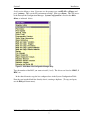
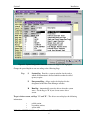
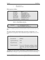
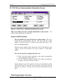
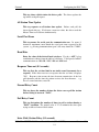
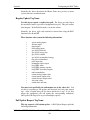
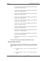
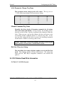
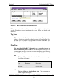
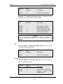
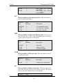
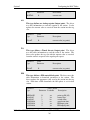
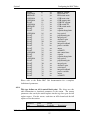
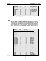
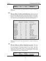
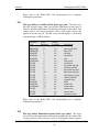
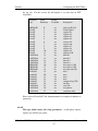
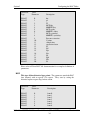
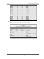
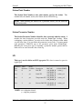
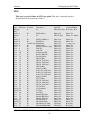
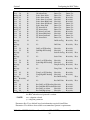
SPARTAN CONTROLS LTD.
USDATA - FISHER ROC DRIVER
USER’S MANUAL
NT - 32 BITS
SUPPORTS ECS
Version 1.0.1
April 1999
IMPORTANT NOTICE
Spartan Controls Ltd. (SCL) reserves the right to revise and improve the software and
documentation at any time and without notice.
SCL makes no warranties, either expressed or implied, regarding the Fisher ROC Driver
computer software package or its merchantability or fitness for any particular purpose.
SCL shall not be liable for technical or editorial omissions made herein; nor shall SCL be
responsible for incidental or consequential damages resulting from the proper or improper
use of these materials nor from the furnishing and performance of this material. The
information contained herein does not represent a commitment on the part of SCL.
This manual is copyrighted and all rights are reserved. This document is furnished under a
license agreement and may not, in whole or part, be copied, photocopied, reproduced,
translated or reduced to any electronic medium or machine readable form without prior
consent, in writing, from Spartan Controls Ltd.
Copyright © 1994 Spartan Controls Ltd. All Rights Reserved.
Spartan Controls Ltd.
305 - 27 Street S.E.
Calgary, Alberta
T2A 7V2
Phone:(403) 207-0700
Fax: (403) 207-0874
Spartan Controls Ltd.
DEFINITIONS
"Spartan Controls" and "SCL" mean an
Alberta Limited Company with respect to
all Programs acquired by Customer.
"Program" means the SCL software
product (executable program,
documentation and/or data).
"Customer" means the person or
organization in whose name the program
was registered during software
authorization.
"Single Machine" means the computer
upon which the program will be installed
and used, as identified in Customer's
Purchase Order or as acknowledged during
software authorization.
LICENSE
Customer may
(a) use the Program on a Single Machine
at any one time;
(b) copy the Program only as reasonably
necessary to support the authorized use,
modification and merger. Each copy of the
Program made by Customer must include a
reproduction of any copyright notice or
restrictive rights legend appearing in or on
the copy of the Program as received from
SCL.
Customer may not
(a) use the Program on more than one
machine at any one time or in a network
environment (except as authorized in a
separate supplemental licensing
agreement);
(b) transfer the Program to any person or
organization outside of Customer or the
corporation of which Customer is a part
without the prior written consent of SCL;
(c) export or re-export, directly or
indirectly, the Program, any associated
documentation or the direct product
thereof, to any country to which such
export or re-export is restricted by law or
regulation of Canada or any foreign
government having jurisdiction without the
prior authorization, if required, of the
Ministry of External Affairs, Ottawa,
Ontario, Canada and the corresponding
agency of such foreign government or
(d) reverse compile or disassemble the
Program for any purpose.
The design of SCL software products
permits the Program to be downloaded or
shared with additional machines for local
execution. A separate license shall be
required for each such machine with which
the Program may be used or a
supplemental agreement granting a
network or site license shall be required for
the entire configuration or installation
within which the Program may be shared.
Title to the Program and all copies thereof,
but not the media on which the Program or
copies may reside, shall be and remain
with SCL or others from whom SCL has
obtained a licensing right.
Customer shall pay when due all property
taxes that may now or hereafter be
imposed, levied or assessed with respect to
the possession or use of the Program or this
license and shall file all reports required in
connection with such taxes.
THE PROGRAM MAY NOT BE USED,
COPIED, MODIFIED, MERGED OR
TRANSFERRED TO ANOTHER
EXCEPT AS EXPRESSLY PERMITTED
BY THESE TERMS AND CONDITIONS.
UPON TRANSFER OF ANY COPY,
MODIFICATION OR MERGED
PORTION OF THE PROGRAM, THE
LICENSE GRANTED HEREIN IS
AUTOMATICALLY TERMINATED.
TERM
The license granted herein is effective upon
delivery of the Product to the Customer
and shall remain in effect until terminated
as provided herein. The license may be
terminated by Customer at any time upon
written notice to SCL. The license may be
terminated by SCL or any third party from
whom SCL may have obtained a respective
licensing right if Customer fails to comply
with any term or condition, including
timely payment of licensing fees and such
failure is not remedied within thirty (30)
days after notice thereof from SCL or such
third party. Upon termination by either
party, Customer shall return to SCL the
Program and all associated documentation,
together with all copies in any form.
LIMITED WARRANTY
SCL warrants that the media on which the
Program is furnished and the encoding of
the Program on the media will be free from
defects in materials and workmanship for a
period of three (3) months from the date of
shipment. If any such media or encoding
proves defective during the warranty
period, SCL will provide a replacement in
exchange for the defective medium.
Except as to the media on which the
Program is furnished, the Program is
provided "as is" without warranty of any
kind, either express or implied. SCL does
Spartan Controls Ltd.
305 - 27 Street S.E.
Calgary, Alberta T2A 7V2
Phone: (403) 207-0700 * Fax: (403) 207-0874
not warrant that the functions contained in
the Program will meet Customer's
requirements or that operation of the
Program will be uninterrupted or error free.
THIS WARRANTY IS GIVEN BY SCL
WITH RESPECT TO THE PROGRAM IN
LIEU OF ANY OTHER WARRANTIES,
EXPRESS OR IMPLIED. SCL AND ITS
VENDORS DISCLAIM ANY IMPLIED
WARRANTIES OF
MERCHANTABILITY OF FITNESS FOR
A PARTICULAR PURPOSE.
RESPONSIBILITY TO REPLACE
DEFECTIVE MEDIA OR REFUND
CUSTOMER'S PAYMENT IS THE SOLE
AND EXCLUSIVE REMEDY
PROVIDED TO THE CUSTOMER FOR
BREACH OF THIS WARRANTY.
LIMITATION OF LIABILITY
IN NO EVENT SHALL SCL OR OTHERS
FROM WHOM SCL HAS OBTAINED A
LICENSING RIGHT BE LIABLE FOR
ANY INDIRECT, SPECIAL,
INCIDENTAL or CONSEQUENTIAL
DAMAGES ARISING OUT OF OR
CONNECTED WITH CUSTOMER'S
POSSESSION OR USE OF THE
PROGRAM, EVEN IF SCL OR SUCH
OTHERS HAS ADVANCE NOTICE OF
THE POSSIBILITY OF SUCH
DAMAGES.
THIRD PARTY DISCLAIMER
Except as expressly agreed otherwise, third
parties from whom SCL may have obtained
a license right do not warrant the Program,
do not assume any liability with respect to
its use and do not undertake to furnish any
support or information relating thereto.
U.S. GOVERNMENT RESTRICTED
RIGHTS
Use, duplication or disclosure by the
Government is subject to restrictions set
forth in subparagraph (a) through (d) of the
Commercial Computer-Restricted Rights
clause at FAR 52.227-19 when applicable
or in subparagraph (C) (1) (ii) of the Rights
in Technical Data and Computer Software
clause at DFARS 252.277-7013
GENERAL
This agreement contains the entire
agreement between the parties with respect
to the use, reproduction and transfer of the
Program. Neither this Agreement nor the
license granted herein is assignable or
transferable by Customer without the prior
written consent of SCL. This Agreement
and the license granted herein shall be
governed by the laws of the Province of
Alberta, Canada.
Spartan Controls Ltd.
This page intentionally left blank.
Spartan Controls Ltd.
305 - 27 Street S.E.
Calgary, Alberta T2A 7V2
Phone: (403) 207-0700 * Fax: (403) 207-0874
ROC Driver User’s Manual
Table of Contents
TABLE OF CONTENTS
Document revision history
ii
1. Introduction
2
1.1 The I/O Interface Module.
2
2. Installing the ROC Driver
6
2.1 INSTALL
6
2.2 Editing with the Configuration Manager Utility.
6
3. Configuring the ROC Tables
12
3.1 Introduction to ROC Table Configuration
12
3.2 ROC Driver Communication Information Screen
13
3.2
13
3.3 ROC Station Control screen
17
3.3
17
3.4 ROC Station Read/Write Information
22
3.4
22
Glossary
41
Index
44
USDATA - FISHER ROC Driver User’s Manual (NT - 32 BITS)
i
Version 1.0.1
ROC Driver User’s Manual
Table of Contents
Document Revision History
Version #
1.0.1
Description
Applies to Versions 1.06, 1.08.1, 1.10.1, 2.30.1
USDATA - FISHER ROC Driver User’s Manual (NT - 32 BITS)
ii
Date
April, 1999
Version 1.0.1
Section 1
Introduction
Section 1
INTRODUCTION
USDATA - FISHER ROC Driver User’s Manual (NT - 32 BITS)
1
Version 1.0.1
Section 1
Introduction
1. Introduction
This manual is designed to provide an overview of operations for the USDATA -Fisher
ROC Driver. It will act as a supplement to other supplied documentation. It is assumed that
the operator has at least basic knowledge of PC functions in the WINDOWS and DOS
environments.
1.1 The I/O Interface Module.
An Input/Output interface module is the communications link that lets
FactoryLink WINDOWS NT talk with any of the Fisher Remote Operations
Controllers (306, 312, 364 and the new ROC 407). It links physically and
electronically to the ROC. You must know how you want to define your data and
how the FactoryLink configuration manager defines data before you configure the
I/O interface module. Throughout this manual we refer to the ROC protocol in
Fisher publication form A4199.
Each ROC has a particular number of Soft Points. A Soft Point is a reserved
block of memory that stores information from a program. The ROC has up to 32
reserved blocks of memory. Each of these 32 Soft Points has 20 Data Points
inside it. Each Data Point is a location for a value. These values helps store the
information compiled by the ROC's program. Ultimately, the Host computer
accesses the information of the program from the Soft Points.
There are several other terms you should know. A Parameter describes the limits
of a given field, address or location. For example, an Analog Input has many
parameters, including Engineering Units, Low AI, Hi AI. Implemented means
active. An implemented point is a point currently in use or ready for use. A Field
Point is a final end device and its characteristics. A Field Point usually monitors
and/or generates information in the field.
You must define Data Points in 4 separate locations for everything to work
properly.
1. You must define the ROC Field Point. You should know the ROC's
configuration or have it on hand. This manual does not include the
configuration details. You will find them in the Fisher GV101 Configuration
Software User Manual, Form A4194.
2. You must define your Communications system to receive common driver
information. Common driver information includes serial port name, baud
rate and response time-outs.
Each piece connects to an individual
communications channel.
3. You must define the Control Points of the ROC station. Each active
station's configuration differs. The fields in this part of the database define the
USDATA - FISHER ROC Driver User’s Manual (NT - 32 BITS)
2
Version 1.0.1
Section 1
Introduction
common points between the individual stations. These points include station
name, ROC address, ROC group, communication status flags, etc.
4. You must use the ROC Station Read/Write Information to define the
individual Data Points. You must make 1 separate database entry for each
point. This entry consists of a tag name, point type, point number, parameter
number, etc.
The Spartan Controls Ltd. ROC Driver uses a standard serial asynchronous
port (RS232C). The communication channel is always open. The first to "talk"
(transmit) is the first to get “heard” (received).
The standard serial asynchronous port attaches to a Personal Computer (PC). The
driver does not support smart communication boards like the IBM Arctic Card. The ROC
driver assumes a Full Duplex circuit is available, although it may actually use Semi- or Halfduplex circuits. As a result, the driver continuously listens for received data. This
discrepancy between Full and Half Duplex circuitry does not affect communication. This
manual assumes all communication channel equipment (i.e. modems, radios) works properly.
USDATA - FISHER ROC Driver User’s Manual (NT - 32 BITS)
3
Version 1.0.1
Section 1
Introduction
This page intentionally left blank.
USDATA - FISHER ROC Driver User’s Manual (NT - 32 BITS)
4
Version 1.0.1
Section 2
Installation
Section 2
INSTALLING THE ROC DRIVER
USDATA - FISHER ROC Driver User’s Manual (NT - 32 BITS)
5
Version 1.0.1
Section 2
Installation
2. Installing the ROC Driver
2.1 INSTALL
The INSTALL command installs the drivers and associated files in the specified
directories. This command installs between 4 and 6 drivers. You can configure whichever
driver you want, as they are all the identical. Follow the steps in Sections 2.2 and 2.3 below.
Note that the INSTALL command does not configure FactoryLink for you.
Place the driver diskette in the appropriate floppy drive of the PC.
From the prompt, type: <INSTALL><Enter>
Example: If the diskette is in A drive, change directory to A by typing < cd a:\ >. Then
type: "INSTALL".
You will see a screen similar to the one below. Follow the prompts. You can abort the
installation factor at any time by pressing one of these key sequences: <Ctrl-c> or <CtrlBreak>.
ROC 364 driver installation (1.0) for Windows NT FactoryLink.
Six drivers will be installed, ROC 1, ROC 2, ROC 3, ROC 4, ROC 5 and ROC 6.
Input (control c) or (control break) to abort at any time.
An authorization number will now be requested, with only three tries allowed.
Spartan Controls Installation Authorization No.? xxxxxxxxxx
Your Company Name (3 to 29 chars.)? xxxxxxxxxxx
File C:\FLNT\ac\r1__.ac exists, overwrite (y,n)? y
For each installation, you need an authorization number from Spartan Controls Ltd.
You can get it by telephoning (403) 207-0700. Ask for the SCADA group. To avoid delays
in the installation process, you should get the authorization number before starting. As it
says on the screen, you have only 3 chances to enter the correct authorization number. If you
fail all 3 times, you will return automatically to the Windows NT prompt.
At the bottom of the screen you see a line asking if you want to overwrite an existing file.
Type "y" or "n". Overwriting existing files while installing the drivers is normally OK.
2.2 Editing with the Configuration Manager Utility.
You can edit the "System Configuration" table with the Configuration Manager Utility.
If you are in Windows NT, open the FactoryLink program group. Click on the FactoryLink
USDATA - FISHER ROC Driver User’s Manual (NT - 32 BITS)
6
Version 1.0.1
Section 2
Installation
Configuration Manager icon. If you are at a dos prompt, type <set FLAP = c:\flapp> and
press <return>. This sets the FL environment variable. Now type <flcm>. This will access
to the FactoryLink Configuration Manager. System Configuration is listed in the Main
Menu, as indicated below.
Figure 2-1: Main Menu of the Configuration Manager Utility
Type the number of the ROC you want to install (1 to 6). The drivers are listed as 1 ROC, 2
ROC, etc.
In the shared domain, copy the last configured row in the System Configuration Table.
Paste the row into the blank line directly after it, creating a duplicate. (To copy and paste,
use the Edit pull-down menu).
USDATA - FISHER ROC Driver User’s Manual (NT - 32 BITS)
7
Version 1.0.1
Section 2
Installation
Figure 2-2: System Configuration Information screen with Copy function highlighted.
Change the pasted duplicate row according to the following flags:
Flags
S
Session flag: Provides a separate window for the task to
which all information is directed which can then be called
up may require.
F
Foreground flag: Allows task to be displayed in the
foreground of the Run-Time Manager window.
R
Run flag: Automatically starts the driver when the system
starts. Set the flag to "R" if you do not want a driver
screen.
To get a driver screen, set flags "S" and "F". The driver screen displays the following
information:
•
•
•
polled station,
responding station,
system time,
USDATA - FISHER ROC Driver User’s Manual (NT - 32 BITS)
8
Version 1.0.1
Section 2
Installation
•
•
driver errors and
communication status.
Fill in tag names as follows:
Task Name
Description
Start Trigger
Task Status
Task Message
Display Status
Display Name
Display Descriptor
ROC x
ROC x 364 Driver
TASKSTART_S[1+y]
TASKSTATUS_S[1+y]
TASKMESSAGE_S[1+y]
TASKDSTATUS_S[1+y]
TASKNAME_S[1+y]
TASKDESC_S[1+y]
where x = driver number (1 up to 6)
where y = current number in tag array
Start Order
N
if installing the first task
N+1 if installing the second task, etc.
where N = a number larger than any currently installed task that may download data to the
ROC
Start Order prioritizes which command lines activate first, starting from 1. This
prioritization is very important as some command lines depend on others in order to work
well.
Priority
201
Executable File
BIN/ROC
Application Directory
blank
Program Directory
blank
Program Arguments
N or n for No printer spooling of driver
information. Any other entry, including a blank
entry, will spool driver information to the
printer.
You should start typical tasks like Alarm Manager and Batch Manager before starting
the ROC driver. Starting these typical tasks first eliminates the chance of downloading
USDATA - FISHER ROC Driver User’s Manual (NT - 32 BITS)
9
Version 1.0.1
Section 2
Installation
default values from the ROC. If you do download the ROC default values, you must
reconfigure the ROC all over again.
USDATA - FISHER ROC Driver User’s Manual (NT - 32 BITS)
10
Version 1.0.1
Section 3
Configuring the ROC Tables
Section 3
CONFIGURING THE ROC TABLES
USDATA - FISHER ROC Driver User’s Manual (NT - 32 BITS)
11
Version 1.0.1
Section 3
Configuring the ROC Tables
3. Configuring the ROC Tables
3.1 Introduction to ROC Table Configuration
We use 3 tables to configure the ROC driver. You access them by clicking on the
ROC Driver you want to configure in the Main Menu.
The ROC Driver Communication Information screen is a single line display. It
configures the general type of information needed by the driver.
The ROC Station Control screen consists of one line of information for each
implemented station. It contains a specific station's configuration information. You define
items such as the communications status tag on this screen.
You define specific point information for a particular station on the ROC Station
Read/Write Information screen. There is one Read/Write screen for each implemented
station. Each implemented point for the station needs a separate line on the Read/Write
screen. Explained below is the configuration information you need.
The TAG NAME entry may have up to 16 characters.
WARNING!!
To store the ROC data correctly, each ROC data type maps to one or more
USDATA type points. For example, the USDATA type FLOAT maps to
Engineering Units (EU). You must observe this mapping restriction for all points
when you build your database. Section 3.4 lists the matching types.
While initializing, the driver builds internal tables from the screen information. The
driver checks each entered tag for adherence to the type restriction. All violations will
appear on the driver screen. The driver will not start until you fix each violation. You fix
violations by redefining the tag type to the USDATA type. Check that the ROC tag type
correctly matches the parameter definition of the type point.
To print out a copy of these errors, remove ´n´ from Program Arguments in the System
Configuration Information screen.
USDATA - FISHER ROC Driver User’s Manual (NT - 32 BITS)
12
Version 1.0.1
Section 3
Configuring the ROC Tables
3.2 ROC Driver Communication Information Screen
Figure 3-1: ROC Driver Communication Information screen.
This screen defines the driver common information in only one line.. See
below for more information on each item.
Interleave Poll Tag Name
This tag identifies the requested interleave station number. The driver
checks this tag location before each poll. The driver polls the station
number stored there when it is between each regular poll request. We
know it as interleave mode.
Interleave mode continues until it has made a total of 30 interleave poll
requests. If you set the station to "0" (zero), it returns to "round robin"
polling.
You can start interleave polling in one of 2 ways:
1. Send a non-data request command to any station, automatically
starting interleave on that station; or
2. Use any USDATA function external to the driver by setting the
interleave scan tag to the desired station.
Set the interleave tag to "0" to cancel it. If you set a new interleave station
while interleaving, you cancel the current interleave station and replace it
with the new station. As before, the new station will interleave for 30
polls.
Polled Station Display Tag Name
USDATA - FISHER ROC Driver User’s Manual (NT - 32 BITS)
13
Version 1.0.1
Section 3
Configuring the ROC Tables
This tag shows which station the driver polls. The driver updates the
tag before each poll request.
All Station Time Update
This tag requests an all-station time update. Before each poll, the
driver checks this tag. If it detects a non-zero value, the driver sends the
Master Time to all stations simultaneously.
Serial Port Name
This tag names the serial port for communication use. Its name (9
characters maximum) must match the serial port name expected by the
system. e.g. If using communications port 2, the entry should be "COM2".
Baud Rate
Enter the value of the desired baud rate here. Use the < ALT-/ > key
combination to choose from the table of valid rates. Valid speeds for ROC
communication are 300, 600, 1200, 2400 and 9600 baud.
Response Time-out (0.1 seconds)
This tag lists the set time limit in one-tenth second increments for a
response. If the driver receives no response after the set limit, it displays
"NO". Response time means the time between transmission of the last
poll character and the time the station receives the first character. e.g.
For a 2 second wait time, enter 20.
Normal Retry Count
This tag shows the number of times the driver can re-poll the station
before setting its status to "FAIL".
Fail Retry Count
This tag determines the number of times to poll a station showing a
"FAIL" condition. The normal value is "1" to minimize the time spent
trying to talk to a known failed station.
Inter (Dial) Station Delay (0.1 seconds)
USDATA - FISHER ROC Driver User’s Manual (NT - 32 BITS)
14
Version 1.0.1
Section 3
Configuring the ROC Tables
This delay time serves 2 purposes, depending on the station's
operation mode.
Polled mode: The driver delays transmission for the length of time
you set. You enter the time in one-tenth second increments i.e.
enter 20 for a 2 second wait time. The set time limit can differ for
each poll.
Dial out mode: The driver waits up to this time limit for Data
Carrier Detector (DCD) after dialing the telephone number. Enter
20 to get the typical value for this delay of 2 seconds.
Same Station Delay (0.1 seconds)
The driver delays transmission between multiple polls on the same
station. Enter the time in one-tenth second increments to determine the
length of the delay. e.g. Enter 20 to produce a 2 second wait time.
Default Configuration
The driver operates in four modes: Polled, Monitor, Unsolicited and
Dial Up. Below we describe each mode.
Polled = 1
POLLED mode: The driver makes poll requests in a continuous
first-to-last poll called a "round robin". Only the interleave and
interstation delay times can change "round robin" polling. The
driver sends out commands when it detects that the user has
changed a value or asked for an action.
Monitor = 0
MONITOR mode: The driver continuously monitors the received
data line and processes the data it gets. You would only set your
driver into this mode if you wanted it in a standby or backup
configuration.
Unsolicited = 2 (UNSOL)
UNSOL mode: The driver continuously monitors the received
data line for a valid station upset request. This mode reports to the
driver the exceptions to normal operation. Once the driver receives
a message like this, it immediately polls the identified station to get
that station's data.
If the Station telephone number is in the ROC station control
table, the driver assumes communication is by telephone. In
USDATA - FISHER ROC Driver User’s Manual (NT - 32 BITS)
15
Version 1.0.1
Section 3
Configuring the ROC Tables
this case, the ROC calls the host machine via the telephone line,
connects, and then allows the ROC to solicit a regular and full poll.
The ROC Station Control Table provides the regular poll tag
allowing periodic station polls. The driver sends out commands
when it detects a changed value.
Dial Out = 3 (DIAL)
Dial Out mode: Dial Out mode replaces the continuous "round
robin" polling with a single poll of all active stations. The driver
automatically Dials Out to connect with each station before each
poll. Once the poll finishes, the driver suspends itself until it
detects a change in the regular poll tag. The driver sends out
commands when it detects a changed value.
For the Dial Out mode to work well, you must meet these
requirements:
•
you must use a Hayes compatible modem;
•
you must configure the modem to disconnect if it
loses Data Terminal Ready (DTR) and supply Data
Carrier Detector (DCD) when connected.
You may choose the mode from those available by using the < ALT-/ >
key combination.
Transmit Turn On Delay (0.01 seconds)
After Requesting To Send (RTS), the driver delays for the set amount
of time before sending character transmissions. Enter the time in one
hundredth second increments. e.g. To produce a 0.2 second wait time,
enter 20. In the case of the Dial Out configuration, the time delay comes
after the driver receives the DCD.
NOTE: The driver has hard coded a number of the more obscure
communication channel parameters to minimize the configuration
required. However, you must make sure your ROC and FL values match
and meet each other´s parameters or you will have a breakdown in
communication. The hard coded parameters are as follows:
Number of data bits = 8
Number of stop bits = 1
Parity = (none)
Global Regular Tag Name
USDATA - FISHER ROC Driver User’s Manual (NT - 32 BITS)
16
Version 1.0.1
Section 3
Configuring the ROC Tables
The Global Regular Tag Name tells the driver it needs to start a
regular poll request when it is in the Unsolicited and Dial Out
operation modes. The driver checks this tag regularly. If it is set, the
driver sets all active regular poll tags. Also, you can use this tag to set
individual poll tags.
Global Full Tag Name
This tag performs the same function as the regular poll above except
it relates to the full update request.
Global History Tag Name
This tag performs the same function as the regular poll above except
it relates to the historical data update request.
Configuration Tag Name (Analog)
When you create a tag a screen pops up and asks you to define the tag
(if you want to redefine the tag later press < Ctrl-t >). That pop-up
screen also asks you to define the default value. When the Driver starts,
the Default Configuration Tag Name value becomes the Configuration Tag
Name value. This tag lets you change the driver's mode. Change the
mode by inputting a value between 0 and 3 inclusive, into the
configuration tag name. If you enter a value less than 0 or greater than 3,
nothing happens.
3.3 ROC Station Control screen
Figure 3-2: ROC Station Control screen.
USDATA - FISHER ROC Driver User’s Manual (NT - 32 BITS)
17
Version 1.0.1
Section 3
Configuring the ROC Tables
The ROC Station Control screen defines parameters common to all
individual stations. The drive polls the stations in numerical order, beginning at
station 1. The driver reserves station 0 for future "all station" applications. The
interleave and polled station tags use the station number as defined by this list.
Do not confuse this Station Number with the station's ROC Unit Number. For
example, the station number is 2 if it is second on the list. The actual unit number
for that station might differ completely, depending on its definition (see Unit
Number below). On-screen, the parameters are listed horizontally, spreadsheet
style. We discuss each parameter below.
Station Name
This 16 character name identifies the station and its associated table
as defined in Section 3.4. You can name it as you wish.
Unit Number
This value identifies the station targeted by the poll. It is part of the
transmit message. The Unit Number should match the "ROC Address" as
shown on the ROC System Variables Display (GV101 Panel).
Group Number
This value identifies the group number of the remote station targeted
by the poll. It is part of the transmit message of the poll. The Group
number should match the "ROC Group" as shown on the ROC System
Variables Display (GV101 Panel).
Communications Status Flag
This tag identifies the storage location for the station's communication
status. The driver sets this value to "0" if communications to the targeted
station are NORMAL. The driver sets this value to "1" if communications
to the targeted station have failed.
Restart Status Tag Name (Digital)
This tag detects an RTU restart. The driver writes "1" to the restart
status tag name. The host time automatically writes to the RTU. The
Restart tag resets to "0".
USDATA - FISHER ROC Driver User’s Manual (NT - 32 BITS)
18
Version 1.0.1
Section 3
Configuring the ROC Tables
Poll Count Tag Name
The driver adds 1 to this tag value each time the driver makes a poll
request to the associated station. This count increases incrementally to
approximately 2.147 * 109 (4 bytes). If you need this value to keep daily
and/or hourly counts, you must use a separate program to reset the values
to zero, among other possibilities.
Incomplete Count Tag Name
The driver adds 1 to this tag each time the driver detects an
Incomplete Response to a poll message. An incomplete message
receives one or more characters but failed to finish the transmission in the
allotted time (see response Time Out value). This count increases
incrementally to approximately 2.147 * 109 (4 bytes). If you need this
value to keep daily and/or hourly counts, you must use a separate program
to reset the values to zero, among other possibilities.
No Response Count Tag Name
The driver adds 1 this tag each time the driver gets NO RESPONSE.
A NO RESPONSE defines itself as a poll message that received no
characters in the allotted time. This count increases incrementally to
approximately 2.147 * 109 (4 bytes). If you need this value to keep daily
and/or hourly counts, you must use a separate program to reset the values
to zero, among other possibilities.
Poll Enable Tag Name
This tag's value lets functions outside the driver start or stop polling
individual stations. The driver checks the status of this tag before
polling. If the tag value is not zero, the driver will not poll the station.
This feature removes stations from the regular poll list for station servicing
or other reasons.
Time Update Tag Name
This tag requests a time update for an individual station. The driver
checks this tag before it polls the target station. If the driver finds a nonzero value, it sends the Master Time to the station. The driver
automatically sets this tag value if it detects a station restart status in the
message returned from the station. In addition, functions outside the
driver may set this value any time it needs to download the Master Time.
USDATA - FISHER ROC Driver User’s Manual (NT - 32 BITS)
19
Version 1.0.1
Section 3
Configuring the ROC Tables
Normally, the driver downloads the Master Time once per day to ensure
system-wide time synchronization.
Regular Update Tag Name
Use this tag to request a regular data poll. The driver uses this flag in
the unsolicited mode to provide a background data poll. This poll ensures
data integrity. In the Dial Out mode, it scans the station.
Normally, the driver polls each station for current data using the ROC
function codes, 0 and 167.
These function codes return the following information:
•
•
•
•
•
•
•
•
•
•
•
•
•
•
•
•
•
•
•
•
system analog inputs
discrete inputs
timed inputs
field analog inputs
gas (AGA) flow rate
gas (AGA) energy rate
gas (AGA) volume
gas (AGA) accumulated energy
raw pulse accumulator
pulse input rate
accumulated pulse input
loop (PID) status
loop (PID) primary setpoint
loop (PID) secondary setpoint
tank accumulation
current analog output value
current timed output value
current discrete output value
soft point values
current date and time
You must ask specifically for information not in the above list. You
do this by requesting a full update and historical and soft point request
tags. After a regular data poll, the driver checks the 3 tags. If set, they
trigger the appropriate poll and update the corresponding definitions.
Once polled, the flag resets to prevent multiple requests.
Full Update Request Tag Name
This tag requests a full station update. A Full Update Request polls the
following information:
USDATA - FISHER ROC Driver User’s Manual (NT - 32 BITS)
20
Version 1.0.1
Section 3
Configuring the ROC Tables
•
all parameters for each implemented DIX type point (Table 22
on page 26 of the ROC manual);
•
all parameters for each implemented DOX type point (Table 23
on page 27 of the ROC manual);
•
all parameters for each implemented AIX type point (Table 24
on page 27 of the ROC manual);
•
all parameters for each implemented AOX type point (Table 25
on page 28 of the ROC manual);
•
all parameters for each implemented PIX type point (Table 26
on page 28 of the ROC manual);
•
all parameters for each implemented PID type point (Table 27
on page 29 of the ROC manual);
•
all parameters for each implemented AGA type point (Table 28
on page 29 of the ROC manual);
•
all parameters for each implemented AGAX type point (Table
30 on page 31 of the ROC manual);
•
all parameters for each implemented FST type point (Table 26
on page 34 of the ROC manual);
•
all the above poll requests made on a per point basis for all
parameters.
The received data only updates implemented point parameters.
Historical Update Tag Name
This tag requests an update of all historical type data points defined
for the station. In this example, the tag value targets specific data for the
poll.
•
Use a number between 1 and 31 as the current month's day
number.
•
Use a number between -1 and -31 as the previous month's day
number.
USDATA - FISHER ROC Driver User’s Manual (NT - 32 BITS)
21
Version 1.0.1
Section 3
Configuring the ROC Tables
AGA Parameter Change Tag Name
This parameter marks changes to the AGA values. This tag sets to a
"1" if the following configured AGA parameters change:
0
3
4
7
8
14
15
16
22
43
44
45
47
48
49
50
51
52
53
Manual Command Tag Name
Normally, the driver checks all incoming commands for all stations
after each station poll finishes. In large systems, the checking process
may take several seconds. Specify a tag name in this column to reduce the
delay. When you type a tag into this column, the driver will process only
an incoming station's commands when it is a non-zero tag value. A nonzero tag value setting tells the driver to process the incoming commands
for that station. It then re-sets the tag value to zero.
NOTE: When using a tag in this column, you must set the tag you
need. Normally you would need a "SEND DATA" button.
Dial Out Character String
This slot defines the station telephone number to use in the Dial Out
mode. The telephone number can have 80 characters. The string must
begin with the "AT" Hayes compatible command or the modem will
ignore it.
3.4 ROC Station Read/Write Information
See Figure 3-3 on following page.
USDATA - FISHER ROC Driver User’s Manual (NT - 32 BITS)
22
Version 1.0.1
Section 3
Configuring the ROC Tables
Figure 3-3: ROC Station Read/Write Information
Each implemented station needs one screen. Each implemented point for a
specific station has a separate input line on this screen. Below, we describe each
input line.
Tag Name
This entry contains the tag name for data storage. The tag may be
either an existing tag previously defined or a new tag created to store data.
In either case the USDATA tag type must correspond to the ROC type
definition described below.
Point Type
You must identify the ROC information as a particular type so the
driver can properly process it. Below are the acceptable point types and
a definition of each type. Select this list when configuring a point by using
the < ALT-/ > key combination.
DI
This type defines a status input point. This data returns as part
of a regular poll request.
USDATA
Type
DIGITAL
Valid
Parameter
Description
0
current status
AI
This type defines an Analog Input point. This data returns as
part of a regular poll request.
USDATA - FISHER ROC Driver User’s Manual (NT - 32 BITS)
23
Version 1.0.1
Section 3
Configuring the ROC Tables
USDATA
Type
FLOAT
Valid
Parameter
Description
0
current value (eng units)
Parameter "0" defines field analog values. Parameters 1 to 5
implement the special system analogs as follows:
USDATA
Type
FLOAT
FLOAT
FLOAT
FLOAT
FLOAT
Valid
Parameter
Description
1
2
3
4
5
TX voltage (eng units)
input voltage (eng units)
AUX 2 voltage (eng units)
AUX 1 voltage (eng units)
board temp (eng units)
NOTE
You can individually implement the above parameters as
desired.
TI
This type defines a digital Timed Input point. This data returns
as part of a regular poll request.
USDATA
Type
FLOAT
Valid
Parameter
Description
0
timed value (eng units)
AGAF
This type defines an AGA Flow type point. This data returns as
part of a regular poll request.
USDATA
Type
FLOAT
FLOAT
Valid
Parameter
Description
0
1
current gas flow (MCF/day)
current
energy
flow
(MMBTU/day)
USDATA - FISHER ROC Driver User’s Manual (NT - 32 BITS)
24
Version 1.0.1
Section 3
Configuring the ROC Tables
FLOAT
2
FLOAT
3
total volume since contract
hour (MCF)
total energy since contract
hour (MMBTU)
ACC
This type defines a pulse input type point. This data returns as
part of a regular poll request.
USDATA
Type
LONGANA
FLOAT
FLOAT
Valid
Parameter
Description
0
1
2
raw accumulator counts
rate / unit time (eng units)
total today (eng units)
PIDF
This type defines an abbreviated PID loop point. Note that you
must use this type to define loop information when you want a
regular update (as opposed to a full update).
USDATA
Type
ANALOG
FLOAT
FLOAT
Valid
Parameter
Description
0
1
2
loop status
primary setpoint
secondary setpoint
TANK
This type defines a Tank type point. This data returns as part of
a regular poll request.
USDATA
Type
FLOAT
Valid
Parameter
Description
0
volume since contract hour
DO
This type defines a Digital control point. The driver updates the
status value into the tag slot from the poll it received. The driver
also uses this table information to send commands.
USDATA
Valid
USDATA - FISHER ROC Driver User’s Manual (NT - 32 BITS)
25
Version 1.0.1
Section 3
Configuring the ROC Tables
Type
DIGITAL
Parameter
Description
0
current state
AO
This type defines an Analog setpoint Output point. The driver
uses this information to send the setpoint to the station. It also
updates the current value as received from the station into the tag
slot.
USDATA
Type
FLOAT
Valid
Parameter
Description
0
current value (eng units)
TO
This type defines a Timed discrete Output point. The driver
uses this table information to send the value to the station. The
driver also updates the tag slot with the current value as received
from the station's response to the regular poll request.
USDATA
Type
FLOAT
Valid
Parameter
Description
0
current value (eng units)
PID
This type defines a PID control block point. The driver uses this
table information to download parameters to the station. The
driver updates the parameter value sent by the station into the tag
slot. Each time a PID downloads the full update is set for that
station.
USDATA
Type
MESSAGE
ANALOG
ANALOG
LONGANA
LONGANA
LONGANA
Valid Down
Parameter Loadable
Description
0
1
2
3
4
5
yes
yes
no
no
yes
yes
point tag ID (10)
control type
switch status
actual scan time
PRI input point
PRI output point
USDATA - FISHER ROC Driver User’s Manual (NT - 32 BITS)
26
Version 1.0.1
Section 3
Configuring the ROC Tables
FLOAT
LONGANA
MESSAGE
LONGANA
LONGANA
FLOAT
LONGANA
MESSAGE
FLOAT
FLOAT
LONGANA
FLOAT
FLOAT
FLOAT
FLOAT
FLOAT
FLOAT
FLOAT
FLOAT
LONGANA
FLOAT
FLOAT
LONGANA
FLOAT
FLOAT
FLOAT
FLOAT
FLOAT
FLOAT
FLOAT
FLOAT
6
7
8
9
10
11
12
13
14
15
16
17
18
19
20
21
22
23
24
25
26
27
28
29
30
31
32
33
34
35
36
yes
yes
yes
yes
yes
yes
yes
yes
yes
yes
yes
yes
yes
yes
yes
yes
no
yes
no
yes
yes
yes
yes
yes
yes
yes
yes
yes
no
yes
no
PRI SW setpoint
PRI switch PV
PRI switch mode
OVR input point
OVR output point
OVR SW setpoint
OVR switch PV
OVR switch mode
setpoint
setpoint change/min
loop period
proportional gain
integral gain
derivative gain
scale factor
integral deadband
process variable
output
switch PV
min control time
setpoint
setpoint change/min
loop period
proportional gain
integral gain
derivative gain
scale factor
integral deadband
process variable
output
switch PV
Please refer to the Fisher ROC 364 documentation for a complete
definition of parameters.
AGA
This type defines an AGA control block point. The driver uses this
table information to download parameters to the station. The current
parameter value sent by the station updates into the tag slot as part of a full
update request. For this reason, each time an AGA downloads the full
update sets for that station.
USDATA
Type
Valid
Parameter
Down
Loadable
Description
USDATA - FISHER ROC Driver User’s Manual (NT - 32 BITS)
27
Version 1.0.1
Section 3
Configuring the ROC Tables
MESSAGE
FLOAT
FLOAT
ANALOG
ANALOG
FLOAT
FLOAT
FLOAT
LONGANA
FLOAT
FLOAT
FLOAT
ANALOG
MESSAGE
ANALOG
FLOAT
FLOAT
FLOAT
FLOAT
FLOAT
FLOAT
FLOAT
FLOAT
FLOAT
FLOAT
FLOAT
FLOAT
FLOAT
FLOAT
FLOAT
FLOAT
FLOAT
FLOAT
FLOAT
FLOAT
FLOAT
FLOAT
FLOAT
FLOAT
FLOAT
FLOAT
FLOAT
FLOAT
ANALOG
ANALOG
0
1
2
3
4
5
6
7
8
9
10
11
12
13
14
15
16
17
18
19
20
21
22
23
24
25
26
27
28
29
30
31
32
33
34
35
36
37
38
39
40
41
42
43
44
yes
yes
yes
yes
yes
yes
yes
yes
yes
yes
yes
yes
yes
yes
yes
yes
yes
yes
yes
yes
yes
yes
yes
yes
yes
yes
yes
yes
yes
yes
yes
yes
yes
yes
yes
yes
yes
yes
yes
yes
yes
yes
yes
no
yes
point tag ID (10)
latitude
elevation
calculation method
options
specific gravity
heating value
grav accel corr
scan period
pipe diameter
orifice diameter
orifice MSRD temp
orifice material
description (30)
alarm code
low alarm
high alarm
viscosity
specific heat ratio
contract pressure
contract temp
diff PR low cutoff
grav correction
nitrogen
carbon dioxide
hydrogen sulfide
water
helium
methane
ethane
Propane
n-butane
i-butane
n-pentane
i-pentane
n-hexane
n-heptane
n-octane
n-nonane
n-decane
oxygen
carbon monoxide
hydrogen
spare
enable stacked DP
USDATA - FISHER ROC Driver User’s Manual (NT - 32 BITS)
28
Version 1.0.1
Section 3
Configuring the ROC Tables
LONGANA
LONGANA
LONGANA
LONGANA
FLOAT
FLOAT
FLOAT
FLOAT
FLOAT
45
46
47
48
49
50
51
52
53
yes
yes
yes
yes
yes
yes
yes
yes
yes
low diff PR number
diff PR number
static PR number
temperature number
low diff PR setpoint
high DP setpoint
HW
PF
TF
Please refer to Fisher ROC 364 documentation for a complete definition of
parameters.
DIX
This type defines an auxiliary status input type point. The driver uses
this type for status points where it needs more information on the point. It
also uses this table information to download parameters to the station. The
current parameter value as received from the station also updates into the
tag slot. For this reason, each time a DIX downloads, the full update sets
for that station.
USDATA
Type
MESSAGE
ANALOG
ANALOG
ANALOG
ANALOG
LONGANA
LONGANA
LONGANA
LONGANA
LONGANA
LONGANA
MESSAGE
LONGANA
FLOAT
FLOAT
FLOAT
FLOAT
FLOAT
FLOAT
FLOAT
FLOAT
Valid
Parameter
Down
Loadable
0
1
2
3
4
5
6
7
8
9
10
11
12
13
14
15
16
17
18
19
20
yes
yes
yes
yes
no
yes
yes
yes
yes
yes
yes
yes
yes
yes
yes
yes
yes
yes
yes
yes
yes
Description
point tag ID (10)
filter
status
modes
alarm code
accum value
on counter
off counter
0% count
100% count
max count
units
scan period
zero eng unit
span eng unit
low alarm
high alarm
lolo alarm
hihi alarm
delta alarm
alarm deadband
USDATA - FISHER ROC Driver User’s Manual (NT - 32 BITS)
29
Version 1.0.1
Section 3
Configuring the ROC Tables
FLOAT
LONGANA
21
22
yes
no
eng unit value
TDI count
Please refer to Fisher ROC 364 documentation for a complete definition of
parameters.
DOX
This type defines an auxiliary status output point. The driver uses this
type for status output points where it needs more information on the point.
It also uses this table information to download parameters to the station.
The driver updates the current parameter from the poll request into the tag
slot. For this reason, the full update sets each time a DOX downloads.
USDATA
Type
MESSAGE
LONGANA
ANALOG
ANALOG
ANALOG
ANALOG
LONGANA
MESSAGE
LONGANA
LONGANA
LONGANA
FLOAT
FLOAT
FLOAT
Valid
Parameter
0
1
2
3
4
5
6
7
8
9
10
11
12
13
Down
Loadable
yes
yes
no
yes
yes
no
yes
yes
yes
yes
yes
yes
yes
yes
Description
point tag ID (10)
time on
spare
status
mode
alarm code
accum value
units (10)
cycle time
0% count
100% count
low reading eng unit
hi reading eng unit
eng unit value
Please refer to Fisher ROC 364 documentation for a complete definition of
parameters.
AIX
This type defines an auxiliary Analog Input type point. The driver
uses this type when it needs more information on the point. It also uses
the table information to download parameters to the station. The driver
updates the current parameter values as received from the full poll of the
station into the tag slot. For this reason, the full update is set for that
station each time it performs an AIX download.
USDATA
Type
Valid
Parameter
Down
Loadable
Description
USDATA - FISHER ROC Driver User’s Manual (NT - 32 BITS)
30
Version 1.0.1
Section 3
Configuring the ROC Tables
MESSAGE
MESSAGE
LONGANA
LONGANA
LONGANA
LONGANA
FLOAT
FLOAT
FLOAT
FLOAT
FLOAT
FLOAT
FLOAT
FLOAT
FLOAT
ANALOG
ANALOG
LONGANA
LONGANA
0
1
2
3
4
5
6
7
8
9
10
11
12
13
14
15
16
17
18
yes
yes
yes
yes
yes
yes
yes
yes
yes
yes
yes
yes
yes
yes
yes
yes
no
no
no
point tag ID (10)
units (10)
scan period
filter
adj a/d 0%
adj a/d 100%
low reading eng unit
hi reading eng unit
low alarm eng unit
hi alarm eng unit
lolo alarm eng unit
hihi alarm eng unit
delta alarm eng unit
alarm deadband
filtered eng unit
mode
alarm code
raw A/D input
actual scan
Please refer to Fisher ROC 364 documentation for a complete definition of
parameters.
AOX
This type defines an auxiliary Analog Output type point. The driver
uses this type when it needs more information on the point. The driver
also uses this table information to download parameters to the station. It
updates the current parameter values (from the station's full update), into
the tag slot. For this reason, the full update is set for that station each time
it performs an AOX download.
USDATA
Type
MESSAGE
MESSAGE
LONGANA
LONGANA
FLOAT
FLOAT
FLOAT
ANALOG
ANALOG
LONGANA
Valid
Parameter
0
1
2
3
4
5
6
7
8
9
Down
Loadable
yes
yes
yes
yes
yes
yes
yes
yes
no
no
Description
point tag id (10)
units (10)
adj a/d 0%
adj a/d 100%
low reading eng unit
hi reading eng unit
eng unit value
mode
alarm code
raw a/d output
USDATA - FISHER ROC Driver User’s Manual (NT - 32 BITS)
31
Version 1.0.1
Section 3
Configuring the ROC Tables
Please refer to the Fisher ROC 364 documentation for a complete
definition of parameters.
PIX
This type defines an auxiliary Pulse Input type point. The driver uses
this type for pulse inputs when it needs more information on the point. It
also uses the table information to download parameters to the station. The
station receives the current parameter from a full update request and
uploads it into the tag slot. For this reason, the full update is set for that
station each time a PIX downloads.
USDATA
Type
MESSAGE
MESSAGE
ANALOG
ANALOG
ANALOG
LONGANA
FLOAT
FLOAT
FLOAT
FLOAT
FLOAT
FLOAT
FLOAT
FLOAT
ANALOG
ANALOG
LONGANA
FLOAT
FLOAT
FLOAT
Valid
Parameter
0
1
2
3
4
5
6
7
8
9
10
11
12
13
14
15
16
17
18
19
Down
Loadable
yes
yes
yes
yes
no
yes
yes
yes
yes
yes
yes
yes
yes
yes
yes
no
yes
no
yes
no
Description
point tag ID (10)
units (10)
rate flag
rate period
type
scan period
conversion
low alarm eng unit
hi alarm eng unit
lolo alarm eng unit
hihi alarm eng unit
delta alarm eng unit
alarm deadband
eng unit value
mode
alarm code
accum value
current rate
today's total
yesterday's total
Please refer to the Fisher ROC 364 documentation for a complete
definition of parameters.
FST
This type defines Funnction Sequence Table type points. The driver
also uses this table information to download parameters to the station. The
current parameter value (received as part of a full update request) updates
USDATA - FISHER ROC Driver User’s Manual (NT - 32 BITS)
32
Version 1.0.1
Section 3
Configuring the ROC Tables
the tag slot. For this reason, the full update is set each time an FST
downloads.
USDATA
Type
MESSAGE
FLOAT
FLOAT
FLOAT
FLOAT
FLOAT
FLOAT
FLOAT
FLOAT
FLOAT
FLOAT
FLOAT
LONGANA
LONGANA
LONGANA
LONGANA
MESSAGE
MESSAGE
MESSAGE
ANALOG
ANALOG
ANALOG
ANALOG
ANALOG
ANALOG
LONGANA
LONGANA
LONGANA
Valid
Parameter
0
1
2
3
4
5
6
7
8
9
10
11
12
13
14
15
16
17
18
19
20
21
22
23
24
25
26
27
Down
Loadable
yes
yes
yes
yes
yes
yes
yes
yes
yes
yes
yes
yes
yes
yes
yes
yes
yes
yes
no
yes
yes
yes
yes
yes
yes
yes
yes
yes
Description
point tag ID (10)
result register
register # 1
register # 2
register # 3
register # 4
register # 5
register # 6
register # 7
register # 8
register # 9
register # 10
timer # 1
timer # 2
timer # 3
timer # 4
message # 1 (30)
message # 2 (30)
message data (10)
misc
misc
misc
misc
compare flag SVD
run flag
code size
inst pointer
execution delay
Please refer to Fisher ROC 364 documentation for a complete definition of
parameters.
AGAX
This type defines more AGA loop parameters. A full update request
updates any AGAX type points.
USDATA - FISHER ROC Driver User’s Manual (NT - 32 BITS)
33
Version 1.0.1
Section 3
Configuring the ROC Tables
USDATA
Type
FLOAT
FLOAT
FLOAT
FLOAT
FLOAT
FLOAT
FLOAT
FLOAT
FLOAT
FLOAT
FLOAT
FLOAT
FLOAT
FLOAT
FLOAT
FLOAT
FLOAT
FLOAT
FLOAT
FLOAT
FLOAT
Valid
Parameter
0
1
2
3
4
5
6
7
8
9
10
11
12
13
14
15
16
17
18
19
20
Description
hw
pf
Tf
MCF/day
MMBTU/day
MCFs today
MMBTUs today
MCFs yesterday
MMBTUs yesterday
Pressure extension
C prime
sample time
expansion factor
Fr
Ftf
Fpv
Fgr
Fb
Fpb
Ftb
Fa
Please refer to Fisher ROC 364 documentation for a complete definition of
parameters.
HIST
This type defines historical type points. The parameters match the ROC
data returned with an opcode 128 request. They start by setting the
historical update request flag for that station.
USDATA
Type
FLOAT
FLOAT
FLOAT
FLOAT
FLOAT
FLOAT
FLOAT
Valid
Parameter
0
1
2
3
4
5
6
Description
hour 0
hour 1
hour 2
hour 3
hour 4
hour 5
hour 6
USDATA - FISHER ROC Driver User’s Manual (NT - 32 BITS)
34
Version 1.0.1
Section 3
Configuring the ROC Tables
FLOAT
FLOAT
FLOAT
FLOAT
FLOAT
FLOAT
FLOAT
FLOAT
FLOAT
FLOAT
FLOAT
FLOAT
FLOAT
FLOAT
FLOAT
FLOAT
FLOAT
FLOAT
FLOAT
FLOAT
MESSAGE
ANALOG
ANALOG
7
8
9
10
11
12
13
14
15
16
17
18
19
20
21
22
23
24
25
26
27
28
29
hour 7
hour 8
hour 9
hour 10
hour 11
hour 12
hour 13
hour 14
hour 15
hour 16
hour 17
hour 18
hour 19
hour 20
hour 21
hour 22
hour 23
daily
min
max
mm-dd-yy
month (1-12)
day (1-31)
Please refer to Fisher ROC 364 documentation for a complete definition of
parameters.
SOFT
This type defines Soft type points. The parameters correspond to the
ROC data returned with an opcode 180 request. They start by setting the
Soft Point update request flag for that station. The driver includes any
Soft Points found in the read and write tables in the regular poll.
USDATA
Type
MESSAGE
LONGANA
FLOAT
FLOAT
FLOAT
FLOAT
FLOAT
FLOAT
Valid
Parameter
Down
Loadable
Description
0
1
2
3
4
5
6
7
yes
yes
yes
yes
yes
yes
yes
yes
point tag ID
integer flag
data #1
data #2
data #3
data #4
data #5
data #6
USDATA - FISHER ROC Driver User’s Manual (NT - 32 BITS)
35
Version 1.0.1
Section 3
Configuring the ROC Tables
FLOAT
FLOAT
FLOAT
FLOAT
FLOAT
FLOAT
FLOAT
FLOAT
FLOAT
FLOAT
FLOAT
FLOAT
FLOAT
FLOAT
8
9
10
11
12
13
14
15
16
17
18
19
20
21
yes
yes
yes
yes
yes
yes
yes
yes
yes
yes
yes
yes
yes
yes
data #7
data #8
data #9
data #10
data #11
data #12
data #13
data #14
data #15
data #16
data #17
data #18
data #19
data #20
DATE
This point type retrieves date and time from the ROC.
NOTE
This value returns as part of the regular poll.
USDATA
Type
Valid
Station
Valid
Parameter
Description
MESSAGE
1
0
DATE
e.g.: 08-21-95 = Aug. 21,
1995
MESSAGE
1
1
TIME
e.g.: 11:43:30
USDATA - FISHER ROC Driver User’s Manual (NT - 32 BITS)
36
Version 1.0.1
Section 3
Configuring the ROC Tables
Station Point Number
The Station Point Number is the point number used in the station. This
number links the number used by the station and the USDATA tag.
NOTE: When building the database for a particular station, you can define the
points in any order.
Station Parameter Number
The Station Parameter Number identifies data associated with the station. It
matches the data descriptions provided under the "Point Type" heading. When
configuring a station database, you only need to define the parameters from which
you will draw data. You can define the parameters in any order. You must match
each parameter's USDATA type to the parameter given under "Point Type".
Matching the wrong data type or inputting a parameter number greater than its
limit causes an error when the driver starts up.
MV
This type is used to define an MVS type point. This data is returned as part of a
regular poll.
USDATA Valid
Down
Type
Parameter Loadable
float
0
yes
float
1
yes
float
2
yes
float
3
yes
Description
Diff. EU
ROC 407
312/364 SI MVS
ai16_0/ai20_0/ *softzz_y
ai24_0/ai28_0
Static EU
ai17_0/ai21_0/ *softzz_y+1
ai25_0/ai29_0
Temperature EU ai18_0/ai22_0/ *softzz_y+2
ai26_0/ai30_0
Reverse Diff. EU ai19_0/ai23_0/
ai27_0/ai31_0
*softzz_y+3
*NOTE: zz = softpoint selected
y = softpoint parameter
USDATA - FISHER ROC Driver User’s Manual (NT - 32 BITS)
37
Version 1.0.1
Section 3
Configuring the ROC Tables
MVX
This type is used to define an MVS type point. This data is currently stored in
the host until the new protocol is added.
USDATA
Type Parameter
Message
Only
Analog 1
Analog
Use
Analog 3
Analog 4
Analog 5
Analog 6
float
7
float
8
float
9
float
10
float
11
float
12
float
13
float
14
float
15
float
16
float
17
float
18
float
19
float
20
float
21
float
22
float
23
float
24
float
25
float
26
float
27
Analog 28
Analog 29
float
30
float
31
float
32
float
33
Analog 34
Analog 35
float
36
float
37
Valid
Loadable
0
Down
Description
No
ROC 407
312/364 SI MVS
MVS Point Tag Host Only Host
No
2
MVS Address
No
Future Use
MVS Config
Future Use
Future Use Future
No
No
312/364 only
No
No
No
No
No
No
No
No
No
No
No
No
No
No
No
No
No
No
No
No
No
No
No
No
No
No
No
No
No
No
No
No
MVS poll Method
MVS Spare
MVS Status
MVS Alarms
MVS Controller voltage
Diff. EU
Static EU
Temperature EU
Reverse Diff. EU
Pressure Effect
DP Cal. Min
DP Cal. Val Point 1
DP Cal. Val Point 2
DP Cal. Val Point 3
DP Cal. Max
Static Cal. Min
Static Cal. Val Point 1
Static Cal. Val Point 2
Static Cal. Val Point 3
Static Cal. Max
TT Cal. Min
TT Cal. Val Point 1
TT Cal. Val Point 2
TT Cal. Val Point 3
TT Cal. Max
Cal Command
Cal Type
Set Valve
Manual DP Valve
Manual PRS Valve
Manual TT Valve
DP Alarm Mode
DP Alarm Alarm
DP Alarm Low Limit
DP Alarm High Limit
Future Use
Future Use
Future Use
Future Use
Future Use
Future Use
Future Use
Future Use
Future Use
Future Use
Future Use
Future Use
Future Use
Future Use
Future Use
Future Use
Future Use
Future Use
Future Use
Future Use
Future Use
Future Use
Future Use
Future Use
Future Use
Future Use
Future Use
Future Use
Future Use
Future Use
Future Use
Future Use
Future Use
Host Only
Host Only
Future Use
Future Use
**softzz_y+4
Future Use
Future Use
Future Use
Future Use
Future Use
Future Use
Future Use
Future Use
Future Use
Future Use
Future Use
Future Use
Future Use
Future Use
Future Use
Future Use
Future Use
Future Use
Future Use
Future Use
Future Use
Future Use
Future Use
Future Use
Future Use
Future Use
Future Use
Future Use
Future Use
Future Use
Host Only
Host Only
USDATA - FISHER ROC Driver User’s Manual (NT - 32 BITS)
38
Version 1.0.1
Section 3
float
float
Analog
Analog
float
float
float
float
Analog
Analog
float
float
float
float
Configuring the ROC Tables
38
39
40
41
42
43
44
45
46
47
48
49
50
51
No
No
No
No
No
No
No
No
No
No
No
No
No
No
DP Alarm Deadband
DP Alarm Fault
Static Alarm Mode
Static Alarm Alarm
Static Alarm Low Limit
Static Alarm High Limit
Static Alarm Deadband
Static Alarm Fault
TT Alarm Mode
TT Alarm Alarm
TT Alarm Low Limit
TT Alarm High Limit
TT Alarm Deadband
TT Alarm Fault
Future Use
Future Use
Future Use
Host Only
Host Only
Host Only
Future Use
Future Use
Future Use
Future Use
Host Only
Host Only
Future Use
Future Use
Future Use
Future Use
Future Use
Host Only
Host Only
Host Only
Future Use
Future Use
Future Use
Future Use
Host Only
Host Only
Future Use
Future Use
Message
Only
Message
Only
float
54
float
55
Message
Only
Message
Only
float
58
float
59
Message
Only
Message
Only
float
62
float
63
Message
Only Host Only
Message
Only
float
66
float
67
float
68
float
69
52
No
Diff Point Tag
Host Only
Host
53
No
Diff Units
Host Only
Host
No
No
56
Diff Low EU Reading
Diff High EU Reading
No
Host Only
Host Only
Host Only
Host Only
Static Point Tag Host Only
Host
57
No
Static Units
Host Only
Host
No
No
60
Static Low EU Reading
Static High EU Reading
No
Host Only
Host Only
Host Only
Host Only
Temp Point Tag Host Only
Host
61
No
Temp Units
Host Only
Host
No
No
64
Temp Low EU Reading
Temp High EU Reading
No
Host Only
Host Only
Host Only
Host Only
Rev Diff Point Tag
Host
65
No
Rev Diff Units
Host
No
No
No
No
Rev Diff Low EU Reading Host Only
Rev Diff High EU Reading Host Only
Rev Diff Low Alarm
Host Only
Rev Diff High Alarm
Host Only
Host Only
Host Only
Host Only
Host Only
Host Only
*Host Only - refers to points currently defined in the host that will be added to
the ROC when the new protocol is written.
**NOTE:
zz = softpoint selected
y = softpoint parameter
Parameters 0 to 51 are defined based on information received from Fisher.
Parameters 52 to 69 have been added to accommodate Spartan’s requirements.
USDATA - FISHER ROC Driver User’s Manual (NT - 32 BITS)
39
Version 1.0.1
Section 3
Configuring the ROC Tables
USDATA - FISHER ROC Driver User’s Manual (NT - 32 BITS)
40
Version 1.0.1
Section 4
Glossary
GLOSSARY
A
ACC:
AGA:
AGAF:
AGAX:
AI:
AIX:
Analog:
AO:
AOX:
A pulse input point.
An international equation to determine flow.
AGA Flow point.
Additional AGA loop parameter point.
Analog Input point.
Auxiliary analog input point.
This term describes a device that measures real values.
Analog setpoint Output point.
Auxiliary Analog Output point.
B
Baud:
The communication speed of the modem in bits per second (bps).
D
Data points:
DATE:
DCD:
Dial Out mode:
DI:
Discrete:
DIX:
DO:
DOX:
Driver:
DTR:
Temporary data storage areas for writing and retrieval.
Point type that retrieves date and time from the ROC.
Data Carrier Detector (modem).
When the driver tries to communicate with the ROCs.
A status input point.
This term describes an "on" or "off" device. It is also known as a
digital device.
Auxiliary status (digital) input point.
Digital control Output point.
Auxiliary status (digital) output point.
Also known as the ROC driver.
Data Terminal Ready (modem).
EU:
Engineering units. Internationally recognized measurements.
Flag:
FloBoss:
FST:
An instruction set. Flag types are Foreground, Run and Session.
The latest step in efficient flow monitoring, listed as the ROC 407.
Function Sequence Table.
E
F
USDATA - FISHER ROC Driver User’s Manual (NT - 32 BITS)
41
Version 1.0.1
Section 4
Glossary
H
Hard Coded:
A program fixed in a driver. To change it, you must change the
program itself.
Hayes compatible
modem:
A modem that uses a well-defined and well-documented command
set.
HIST:
A Historical point.
I
Implement:
Increment:
Input:
Interleave:
I/O:
I/O interface
module:
An item that is active, like a station.
Increasing a value by a set value, usually by one.
Gathering information from a device or monitor.
Alternately polling one station between the others. e.g. Station 1,
2, 1, 3, 1, 4, etc. Station 1 is the interleave station.
Input/Output.
The device driver that lets FactoryLink WINDOWS NT talk to the
ROC.
M
Master Time:
The driver time that synchronizes with the ROC clocks.
N
Non-zero:
A number that is anything but a 0 (zero).
O
Opcode:
Output:
The communication language abbreviation for Operational Code.
Sending instructions and information to a device.
P
Parameters:
PID:
PIDF:
PIX:
Polled mode:
The rules that configure a system.
A PID control block point.
Abbreviated PID loop poin.
Auxiliary pulse input point.
When polls are made continuously in a "round robin".
USDATA - FISHER ROC Driver User’s Manual (NT - 32 BITS)
42
Version 1.0.1
Section 4
Glossary
R
RTS:
ROC:
Round Robin
polling:
Request to Send by the Host Modem.
Remote Operator's Control.
The Host polls each station sequentially and then re-polls each
station in the same order.
S
Serial Port:
A socket for plugging in peripheral hardware.
Shared Domain: An area where both the User and the Host have access.
Soft point:
A temporary memory spot where you write data in the ROC.
SOFT:
Soft point.
Spool:
The PC's preparation to print a file.
T
Tag:
TANK:
TI:
TO:
A location for data that triggers a reaction from the driver.
A tank input point.
Timed Input point.
Timed discrete Output point.
USDATA - FISHER ROC Driver User’s Manual (NT - 32 BITS)
43
Version 1.0.1
Section 5
Index
INDEX
A
ACC, 24
Additional AGA, 20, 33
AGA, 19, 20, tc.
AGA Inputs, 19
AGAF, 23
AGAX, 20, 33
AI, 22
AIX, 20, 29, 30
All Station Time Update, 13
ALT /, 13, 15, 16, 22
Analog Input, 22, 29
Analog Inputs, 19
Analog Output, 19, 30
Analog Setpoint Output Point, 25
AO, 25
AOX, 20, 30
Application Directory, 8
authorization, 5
Auxiliary Analog Input, 20, 29, 30
Auxiliary Analog Output, 20, 30
Auxiliary Pulse, 20, 31
Auxiliary Status Input, 20, 28
Auxiliary Status Output, 20, 29
B
Baud Rate, 2, 13
C
Communications Status, 11, 17
D
DATE, 19, 35
date/time, 19
Default, 14, 16
Delay, 13, 14, 15
Description, 8
DI, 22
dial out mode, 14, 15, 19, 21
Dialout Character String, 21
Digital Control Point, 5, 24
Digital Timed Inputs, 23
Discrete Inputs, 19
Discrete Output, 19, 25
Display Descriptor, 8
Display Name, 8
Display Status, 8
DIX, 20, 28
DOX, 20, 29
USDATA - FISHER ROC Driver User’s Manual (NT - 32 BITS)
44
Version 1.0.1
Section 5
Index
E
Executable File, 8
F
field point, 2
FST Points, 20, 32
full duplex, 3
Full Update Request, 16, 19, etc.
G
Group Number, 17
H
Historical Points, 16, 19, 20, 33
I
IBM Arctic Card., 3
Incomplete Count, 18
INSTALL, 5
installation, 5
Inter (Dial) Station Delay, 14
Interleave, 12, 14, 15, 17
Interleave Poll, 12
Interleave Poll TagXE "Tag" Name, 12
Introduction, 11
L
Loop & PID, 19, 24, etc.
M
Mode, 12, 14, etc.
modems, 3
N
No Response Count, 18
P
PID, 19, 20, etc.
PIDF, 24
PIX, 20, 31
Point Type, 3, 22, 35, 36
Poll Count, 18
Poll Enable, 18
polled mode, 14
Polled Station Display, 13
Polled Station Display TagXE "Tag" Name, 13
Priority, 8
Program Arguments, 8
Program Directory, 8
Pulse Inputs, 19, 24, 31
R
Regular Update, 19
Response Timeout, 13
USDATA - FISHER ROC Driver User’s Manual (NT - 32 BITS)
45
Version 1.0.1
Section 5
Index
Restart Status, 17, 18
Retry Count, 13
ROC DriverXE "driver" Communication Information, 11
ROC Station Control, 11
ROC Station Read / WriteXE "Station Read/Write Information" Information, 11
S
Same Station Delay, 14
SCADA, 5
serial asynchronous port, 3
Serial Port, 2, 13
Serial Port Name, 13
Soft Points, 19, 34
Start Order, 8
Start Trigger, 8
Station, 35
Station Control, 3, 11, 15, 16
Station Name, 3, 17
station number, 12, 13, 17
Station Parameter Number, 36
Station Point Number, 35
Station Read/Write Information, 11, 21
T
tables, 11
Tag, 3, 8, etc.
TAG NAME, 11
Tank Inputs, 19, 24
Task Message, 8
Task Name, 8
Task Status, 8
TI, 23
Time Update, 13, 18
Timed Inputs, 19
Timed Output, 19
Transmit Turn On, 15
U
Unit Number, 14, 17
USDATA - FISHER ROC Driver User’s Manual (NT - 32 BITS)
46
Version 1.0.1