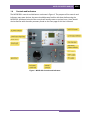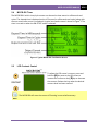
1
MCCB-500 MOLDED-CASE CIRCUIT BREAKER TESTER USER’S MANUAL Vanguard Instruments Company, Inc. 1520 S. Hellman Ave. Ontario, California 91761, USA TEL: (909) 923-9390 FAX: (909) 923-9391 January 2015 Revision 1.0 MCCB-500 USER’S MANUAL REV 1 SAFETY SUMMARY FOLLOW EXACT OPERATING PROCEDURES Any deviation from the procedures described in this user’s manual may create one or more safety hazards, damage the MCCB-500, or cause errors in the test results. Vanguard Instruments Co., Inc. assumes no liability for unsafe or improper use of the MCCB-500. The following safety precautions must be observed during all phases of test setup, test hookups, testing, and test lead disconnection. SAFETY WARNINGS AND CAUTIONS The MCCB-500 shall be used only by trained operators. All circuit breakers under test shall be off-line and fully isolated. SERVICE AND REPAIR • Do not install substitute parts or perform any unauthorized modification to any MCCB-500 test unit. • Repairs must be performed only by Vanguard Instruments Company factory personnel or by an authorized repair service provider. Unauthorized modifications can cause safety hazards and will void the manufacturer’s warranty. EQUIPMENT RATINGS IP Rating: The enclosure for the MCCB-500 an IP rating of 21. Pollution Degree: The MCCB-500 has a pollution rating of 2. Operating Voltage: The MCCB-500 is rated for use with an operating voltage of 120V or 240V, auto-ranging ±10% of selected voltage. Power Cord: The MCCB-500 is supplied with a 16 AWG, 16A power cord with an Amphenol MS3106 style plug. Replacement cable shall have the same or better rating and is available through the manufacturer. VENTILATION REQUIREMENTS The MCCB-500 must be operated with the enclosure lid open. REPLACEMENT FUSES The MCCB-500 uses two 250V/8A Fast Blow fuses (F8A 250V). SAFETY SYMBOLS Indicates that caution should be exercised Indicates location of chassis ground terminal CLEANING To clean the MCCB-500: • Disconnect all cables and turn the unit off. • Use a soft, lint-free cloth to wipe all surfaces clean. • Avoid getting moisture in openings and connectors. • Don't use any cleaning products or compressed air. i REV 1 MCCB-500 USER’S MANUAL TABLE OF CONTENTS CONVENTIONS USED IN THIS DOCUMENT ..................................................................................... 1 1.0 INTRODUCTION .................................................................................................................... 2 1.1 General Description and Features ................................................................................... 2 1.2 Furnished Accessories ...................................................................................................... 3 1.3 MCCB-500 Technical Specifications ................................................................................. 4 1.4 Controls and Indicators .................................................................................................... 5 2.0 FUNCTIONAL DESCRIPTION ................................................................................................. 6 2.1 MCCB-500 AC Current Source.......................................................................................... 6 2.2 MCCB-500 Current Output Control ................................................................................. 7 2.3 Timer Stop Input and Control .......................................................................................... 8 2.4 MCCB-500 Timer .............................................................................................................. 9 2.5 LCD Contrast Control ....................................................................................................... 9 2.6 50/60 Hz Cycle Time Selection ....................................................................................... 10 3.0 OPERATING PROCEDURES ................................................................................................. 11 3.1 Testing the Time Delay of a Low Voltage Circuit Breaker.............................................. 11 LIST OF TABLES Table 1. MCCB-500 Technical Specifications .................................................................................. 4 Table 2. MCCB-500 Current Output ................................................................................................ 6 Table 3. MCCB-500 Overload Current Output ................................................................................ 6 LIST OF FIGURES Figure 1. MCCB-500 Controls and Indicators .................................................................................. 5 Figure 2. Typical MCCB-500 Test Results Screen ............................................................................ 9 Figure 3. Typical MCCB-500 Application ....................................................................................... 11 ii MCCB-500 USER’S MANUAL REV 1 CONVENTIONS USED IN THIS DOCUMENT This document uses the following conventions: • A key, switch, input, or knob on the MCCB-500 is indicated as [KEY], [SWITCH], [INPUT], [KNOB]. • Warning messages are indicated as: Warning message WARNING • Important notes are indicated as: Note details NOTE 1 REV 1 MCCB-500 USER’S MANUAL 1.0 INTRODUCTION 1.1 General Description and Features The Vanguard MCCB-500 is a microprocessor-based high current circuit breaker test set. This unit provides a variable high current source, control, metering, and timing circuitries for testing overload relays and thermal and magnetic circuit breakers. Built-in Timer The MCCB-500's built-in timer displays the test results in milliseconds and cycles. The cycle time (50 or 60 Hz) is selectable by the user. Timer reading range is from 0.1 ms to 2 hours. Timer resolution is 0.1 ms and the timer accuracy is ±0.1% of reading, ±0.1 ms. For mer reading range of 100s ̶ 999s the resolution is 1 ms. For mer reading range of 1000s ̶ 7200s the resolution is 10 ms. NOTE Timer Start Mode: Timer can be started when the current source is turned on. Timer Stop Mode: Timer can be stopped with the removal of the test current or detection of a status change of dry contact or voltage input. Current Source The MCCB-500's current source has 3 outputs: 500A @ 4vac, 125A @ 14Vac, and 25A @ 70Vac. The current sources can output short-duration overload conditions. This feature is convenient for performing instantaneous trip tests of molded case circuit breakers, or testing the time delay characteristics of magnetic overload relays. Test current is measured and displayed on a 128 x 64 pixel back-lit LCD screen that is clearly visible in direct sun light or low light levels. Control switches are used to turn the current source on and off, select the timer stop input type (current mode, dry contact, or wet contact), and control the LCD contrast. A "momentary" mode can turn on the current source, capturing the current reading and displaying the value on the LCD. This feature can be used to set the test current and minimizes the possibility of overheating the device under test. Test current is turned on at the zero crossing point using a solid state device for reliability and precision timing. Built-in Current Meter The MCCB-500 features a built-in current meter that displays the test current (100mA ̶ 3000A). Current reading accuracy is: ±1% of reading, ±2 digits. Test results (current reading and time) are retained after performing a test so that the test results can be reviewed. This is a convenient feature when used with the momentary mode to preset the test current to avoid overheating the circuit breaker. 2 MCCB-500 USER’S MANUAL REV 1 Current Source Thermal Protection Built in thermal sensor allows the microprocessor to monitor the transformer current source operating temperature. 1.2 Furnished Accessories The MCCB-500 comes furnished with the following: • • • • Two 5-foot (1.5m) #2/0 current cables Two 8-foot (2.5m) external timer input cables with alligator clips. One ground cable One power cord 3 REV 1 1.3 MCCB-500 USER’S MANUAL MCCB-500 Technical Specifications Table 1. MCCB-500 Technical Specifications TYPE 500 Ampere current source PHYSICAL SPECIFICATIONS Dimensions: 16”W x 14”H x 13”D (40.6 cm x 35.5 cm x 33.0 cm); Weight: 93 lbs (42.2 kg) INPUT VOLTAGE 100 – 120 Vac or 200 – 240 Vac (factory pre-set), 50/60 Hz INTERNAL CURRENT METER 1A – 3,000A; accuracy: 1% of reading, ±2 digits MEASUREMENT METHOD Isolated CT TIMER STOP INPUTS Voltage input (20V – 300V, dc or peak ac), dry contact input, or removal of test current TIMER READING RANGE 0.1ms – 2 hours (also displayed in cycles); accuracy: 0.1% of reading, ±0.1ms OUTPUT CURRENTS 500A @ 4V, 125A @ 14V, 25A @ 70V DISPLAY back-lit LCD screen (128 x 64 pixels); viewable in bright sunlight and lowlight levels HUMIDITY 90% RH @ 40°C (104°F) non-condensing SAFETY designed to meet IEC61010 (1995), UL61010A-1, CSA-C22.2 standards ENVIRONMENT Operating: -10˚C to 50˚ C (15˚F to +122˚ F); Storage: -30˚ C to 70˚ C (-22˚F to +158˚ F) ALTITUDE 2,000 m (6,562 ft) to full safety specifications CABLES FURNISHED ACCESSORIES WARRANTY two 5-foot (1.5m) #2/0 current cables, two 8-foot (2.5m) external timer input cables with alligator clips, one ground cable, one power cord shipping case one year on parts and labor The above specifications are valid at nominal operating voltage and at a temperature of 25°C (77°F). Specifications may change without prior notice. NOTE 4 MCCB-500 USER’S MANUAL 1.4 REV 1 Controls and Indicators The MCCB-500’s controls and indicators are shown in Figure 1. The purpose of the controls and indicators may seem obvious, but users should become familiar with them before using the MCCB-500. Accidental misuse of the controls will usually cause no serious harm. Users should also be familiar with the safety summary found on the front page of this User’s Manual. Figure 1. MCCB-500 Controls and Indicators 5 REV 1 MCCB-500 USER’S MANUAL 2.0 FUNCTIONAL DESCRIPTION 2.1 MCCB-500 AC Current Source The MCCB-500 provides three AC current outputs. AC test current is set by the [CURRENT CONTROL] knob. This test current is measured and displayed on the LCD screen. The MCCB500’s output current ratings are shown in Table 2 and Table 3 below. Table 2. MCCB-500 Current Output CURRENT OUTPUT 500A @ 4V 125A @ 14V 25A @ 70V Table 3. MCCB-500 Overload Current Output CURRENT ON TIME OFF TIME 40% (200A) Continuous Continuous 100% (500A) 30 minutes 30 minutes NOTE: The MCCB-500 is capable of delivering 2600A instantaneous current. 6 MCCB-500 USER’S MANUAL 2.2 REV 1 MCCB-500 Current Output Control The MCCB-500 current source output is controlled by the [] and [] keys. Three control modes are available: ON-START, OFF, and MOMT. The OFF mode indicates that both the current source output and timer are off. The MOMT mode turns on the current source momentarily. To turn on the current source, press and hold the [] key. The LED indicator next to the “MOMT” label will turn on indicating that the MCCB-500 current source is on. The output current will also be displayed on the LCD screen and the last current reading remains displayed on the screen. The MCCB-500 current output can now be set by turning the [CURRENT CONTROL] knob. Release the [] key to turn off the current source. The ON-START mode turns on the MCCB-500 current source and timer. This initiates a test and is stopped by using the [TIMER STOP] inputs. The test results will be displayed on the LCD screen. The test can also be terminated by pressing the [] key. 7 REV 1 2.3 MCCB-500 USER’S MANUAL Timer Stop Input and Control After a test is started, the MCCB-500 timer can be stopped and the current source turned off using one of three modes: dry contact input, wet contact input, or interruption of the MCCB-500's current output. The [] key is used to select the desired mode. When the DRY CONTACT mode is selected, the MCCB500 will output a DC voltage to the [TIMER STOP] terminals to sense the state of the dry contacts. A change in this dry contact state will stop the timer and turn off the current source. In WET CONTACT mode, the MCCB-500 will sense an AC or DC voltage applied to the [TIMER STOP] terminals. The OFF state is a voltage from 0 to 10 V ac/dc. The ON state is a voltage from 24 to 300 V ac/dc. A change in the voltage state will stop the timer and turn off the current source. In CURRENT mode, an interruption of the MCCB-500's current source output (CB contact opened) will stop the timer and turn off the current source. Both the DRY CONTACT and WET CONTACT modes require an external input to the MCCB-500 via the [TIMER STOP] terminals. The MCCB defaults to CURRENT mode when it is first turned on. NOTE 8 MCCB-500 USER’S MANUAL 2.4 REV 1 MCCB-500 Timer The MCCB-500’s built-in time/cycle counter can be used to time events in milliseconds and cycles. The elapsed time is displayed on the LCD screen (in milliseconds and cycles) along with the test current after a test is completed. A typical test results screen is shown in Figure 2. The timer is turned on when the ON-START mode is selected. Figure 2. Typical MCCB-500 Test Results Screen 2.5 LCD Contrast Control To adjust the LCD screen’s contrast, press and hold the [] key next to the LCD screen to increase the contrast or the [] key to decrease the contrast. Release the key when the desired contrast level has been reached. The MCCB-500 will store the current LCD setting in non-volatile memory. NOTE 9 REV 1 2.6 MCCB-500 USER’S MANUAL 50/60 Hz Cycle Time Selection To toggle between the 50 and 60Hz cycle times, press and hold both the [] and [] keys to the left of the LCD screen. The message "50 Hz Set!" or "60 Hz Set!" will be displayed on the LCD screen. This value is also displayed on the test results screen. 10 MCCB-500 USER’S MANUAL 3.0 OPERATING PROCEDURES 3.1 Testing the Time Delay of a Low Voltage Circuit Breaker REV 1 Figure 3 illustrates a typical connection of the MCCB-500 to a molded case circuit breaker to test its “Open Time Delay”. The MCCB-500 injects a test current through a circuit breaker contact. This current is sensed by the circuit breaker control circuit. The time delay test starts by injecting a preset current to the circuit breaker contact and ends when the circuit breaker contact is opened and interrupts the test current. Figure 3. Typical MCCB-500 Application 11 REV 1 MCCB-500 USER’S MANUAL Use the steps below to test the time delay of a protection relay: a. Connect the Safety Ground to the MCCB-500. b. Connect the AC power cord. c. Connect the Current Cables from the MCCB-500 to the bus as shown in Figure 3. d. Turn the [CURRENT CONTROL] knob to zero. e. Turn on the [POWER SWITCH]. f. Hold the [] key to momentarily turn on the current source. g. Turn the [CURRENT CONTROL] knob to set the desired current. h. Release the [] key. i. Press the [] key to select the ON-START mode and start the test. The MCCB-500 will inject the preset current into the bus and turn on the timer. The timer will stop and the current source will be turned off when the circuit breaker is opened. A typical MCCB500 time delay test results screen is shown below: NOTE 12 In the above test, the timer will be stopped if the current source is interrupted (circuit breaker opened). The test results will be displayed and remain displayed on the screen. If the test is aborted by the operator, the last test results will be displayed and remain displayed on the screen. 1520 S. Hellman Ave • Ontario, CA 91761 • USA Phone: 909-923-9390 • Fax: 909-923-9391 www.vanguard-instruments.com Copyright © 2015 by Vanguard Instruments Company, Inc. MCCB-500 User’s Manual • Revision 1.0 • January 9, 2015 • TA