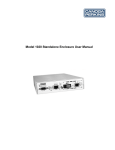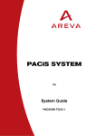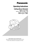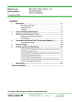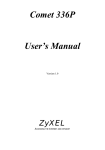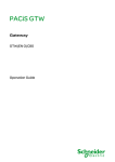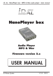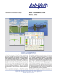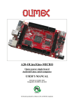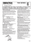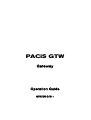
1
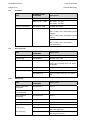
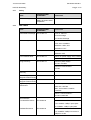
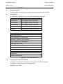
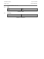
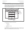
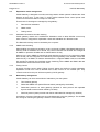
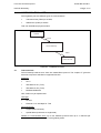
PACiS GTW
Gateway
Operation Guide
GTW/EN O/B11
Operation Guide
PACiS Gateway
GTW/EN O/B11
Page 1/2
PACiS Gateway
CONTENT
Safety & Handling
GTW/EN SA/B11
Technical Data
GTW/EN TD/B11
Introduction
GTW/EN IT/B11
Hardware Description
GTW/EN HW/B11
Functional Description
GTW/EN FT/B11
Glossary
GTW/EN LX/B11
GTW/EN O/B11
Operation Guide
Page 2/2
PACiS Gateway
BLANK PAGE
Safety & Handling
GTW/EN SA/B11
PACiS Gateway
SAFETY & HANDLING
Safety & Handling
GTW/EN SA/B11
PACiS Gateway
Page 1/8
CONTENT
1.
INTRODUCTION
3
2.
SAFETY
4
2.1
Health and Safety
4
2.2
Explanation of symbols and labels
4
2.3
Installing, Commissioning and Servicing
4
2.4
Decommissioning and Disposal
4
3.
GUARANTIES
5
4.
COPYRIGHTS & TRADEMARKS
6
4.1
Copyrights
6
4.2
Trademarks
6
5.
WARNINGS REGARDING USE OF AREVA T&D – AUTOMATION
PRODUCTS
7
GTW/EN SA/B11
Safety & Handling
Page 2/8
PACiS Gateway
BLANK PAGE
Safety & Handling
PACiS Gateway
1.
GTW/EN SA/B11
Page 3/8
INTRODUCTION
The present document is a PACiS GATEWAYS chapter of the documentation binders. It
describes the safety, handling, packing and unpacking procedures applicable to PACiS
GATEWAYS software tools.
GTW/EN SA/B11
Safety & Handling
Page 4/8
2.
SAFETY
WARNING:
2.1
PACiS Gateway
THIS SAFETY SECTION SHOULD BE READ BEFORE COMMENCING
ANY WORK ON THE EQUIPMENT.
Health and Safety
The information in the Safety Section of the product documentation is intended to ensure
that products are properly installed and handled in order to maintain them in a safe condition.
It is assumed that everyone who will be associated with the equipment will be familiar with
the contents of the Safety Section and all Safety documents related to the PC and
Communication networks.
2.2
Explanation of symbols and labels
The meaning of symbols and labels may be used on the equipment or in the product
documentation, is given below.
2.3
Installing, Commissioning and Servicing
Equipment operating conditions
The equipment (PC and communication network supporting PACiS GATEWAYS) should be
operated within the specified electrical and environmental limits.
Fibre optic communication
Where fibre optic communication devices are fitted, these should not be viewed directly.
Optical power meters should be used to determine the operation or signal level of the device.
2.4
Decommissioning and Disposal
Disposal:
It is recommended to avoid incineration and disposal of the PC and the communication
network supporting PACiS GATEWAYS. The products should be disposed of in a safe
manner.
Safety & Handling
PACiS Gateway
3.
GTW/EN SA/B11
Page 5/8
GUARANTIES
The media on which you received AREVA T&D – Automation software are guaranted not to
fail executing programing instructions, due to defects in materials and workmanship, for a
period of 90 days from date of shipment, as evidenced by receipts or other documentation.
AREVA T&D – Automation will, at its option, repair or replace software media that do net
execute programming instructions if AREVA T&D – Automation receive notice of such
defects during the guaranty period. AREVA T&D – Automation does not guaranty that the
operation of the software shall be uninterrupted or error free.
A Return Material Authorisation (RMA) number must be obtained from the factory and clearly
marked on the package before any equipment acceptance for guaranty work.AREVA T&D –
Automation will pay the shipping costs of returning to the owner parts, which are covered by
warranty.
AREVA T&D – Automation believe that the information in this document is accurate. The
document has been carefully reviewed for technical accuracy. In the event that technical or
typographical errors exist, AREVA T&D – Automation reserves the right to make changes to
subsequent editions of this document without prior notice to holders of this edition. The
reader should consult AREVA T&D – Automation if errors are suspected. In no event shall
AREVA T&D – Automation be liable for any damages arising out of or related to this
document or the information contained in it.
Expect as specified herein, AREVA T&D – Automation makes no guaranties, express or
implied and specifically disclaims and guaranties of merchantability or fitness for a particular
purpose.
Customer's rights to recover damages caused by fault or negligence on the part
AREVA T&D – Automation shall be limited to the amount therefore paid by the customer.
AREVA T&D – Automation will not be liable for damages resulting from loss of data, profits,
use of products or incidental or consequential damages even if advised of the possibility
thereof.
This limitation of the liability of AREVA T&D – Automation will apply regardless of the form of
action, whether in contract or tort, including negligence. Any action against AREVA T&D –
Automation must be brought within one year after the cause of action accrues. AREVA
T&D – Automation shall not be liable for any delay in performance due to causes beyond its
reasonable control.
The warranty provided herein dues net cover damages, defects, malfunctions, or service
failures caused by owner's failure to follow the AREVA T&D – Automation installation,
operation, or maintenance instructions; owner's modification of the product; owner's abuse,
misuse, or negligent acts; and power failure or surges, fire, flood, accident, actions of third
parties, or other events outside reasonable control.
GTW/EN SA/B11
Page 6/8
4.
COPYRIGHTS & TRADEMARKS
4.1
Copyrights
Safety & Handling
PACiS Gateway
Under the copyright laws, this publication may not be reproduced or transmitted in any form,
electronic or mechanical, including photocopying, recording, storing in an information
retrieval system, or translating, in whole or in part, without the prior written consent of
AREVA T&D – Automation.
4.2
Trademarks
PACiS, PACiS SCE, PACiS ES, PACiS SMT, PACiS PS, PACiS SCE, T&D EAI, pacis.biz
and pacis.com- are trademarks of AREVA T&D – Automation. Product and company names
mentioned herein are trademarks or trade names of their respective companies.
Safety & Handling
PACiS Gateway
5.
GTW/EN SA/B11
Page 7/8
WARNINGS REGARDING USE OF AREVA T&D – AUTOMATION
PRODUCTS
AREVA T&D – Automation products are not designed with components and testing for a
level of reliability suitable for use in or in connection with surgical implants or as critical
components in any life support systems whose failure to perform can reasonably be
expected to cause significant injuries to a human.
In any application, including the above reliability of operation of the software products can be
impaired by adverse factors, including -but not limited- to fluctuations in electrical power
supply, computer hardware malfunctions, computer operating system, software fitness,
fitness of compilers and development software used to develop an application, installation
errors, software and hardware compatibility problems, malfunctions or failures of electronic
monitoring or control devices, transient failures of electronic systems (hardware and/or
software), unanticipated uses or misuses, or errors from the user or applications designer
(adverse factors such as these are collectively termed "System failures").
Any application where a system failure would create a risk of harm to property or persons
(including the risk of bodily injuries and death) should not be reliant solely upon one form of
electronic system due to the risk of system failure to avoid damage, injury or death, the user
or application designer must take reasonably steps to protect against system failure,
including -but not limited- to back-up or shut-down mechanisms, not because end-user
system is customised and differs from AREVA T&D – Automation' testing platforms but also
a user or application designer may use AREVA T&D – Automation products in combination
with other products.
These actions cannot be evaluated or contemplated by AREVA T&D – Automation; Thus,
the user or application designer is ultimately responsible for verifying and validating the
suitability of AREVA T&D – Automation products whenever they are incorporated in a
system or application, even without limitation of the appropriate design, process and safety
levels of such system or application.
GTW/EN SA/B11
Safety & Handling
Page 8/8
PACiS Gateway
BLANK PAGE
Technical Data
GTW/EN TD/B11
PACiS Gateway
TECHNICAL DATA
Technical Data
PACiS Gateway
GTW/EN TD/B11
Page 1/12
CONTENT
1.
INTRODUCTION
3
1.1
General features
3
2.
INDUSTRIAL PC CHARACTERISTICS
4
2.1
Operating System
4
2.2
Configuration
4
2.3
Communication ports with SCADA
4
2.4
Ethernet Communication port
5
2.5
Rated Values
5
2.6
DC auxiliary supply
5
2.7
AC auxiliary supply
5
2.8
Insulation
6
2.9
Environmental
6
2.10
Mechanical
6
2.11
Safety
7
2.12
EMC TESTS
7
2.13
Wiring
8
3.
SOFTWARE GATEWAY CHARACTERISTICS
9
3.1
Number of Data Points
9
3.2
Response time
9
3.3
UCA2 Avalanche
9
4.
GI74 CHARACTERITICS
10
4.1
Operating System
10
4.2
Configuration
10
4.3
Communication ports with SCADA
10
5.
LIMITS AND PERFORMANCES
11
5.1
Exchanging message with SCADA
11
5.2
UCA2 acquisition
11
5.3
Time Performance
11
6.
SYSTEM DEPENDABILITY
12
6.1
MTBF
12
6.2
Availability
12
GTW/EN TD/B11
Technical Data
Page 2/12
PACiS Gateway
BLANK PAGE
Technical Data
GTW/EN TD/B11
PACiS Gateway
1.
Page 3/12
INTRODUCTION
This document is a chapter of PACiS Gateway documentation binder. It is the chapter
Technical Data (TD) of this Product.
PACiS Gateway is a software package installed on an industrial PC to increase
environmental capabilities. Technical characteristics of this PC are described thereafter.
The GI74 protocol is implemented on a specific platform based also on an industrial PC
described thereafter.
For more information about hardware description see chapter HW. For more information
about connection diagrams see chapter CO.
1.1
General features
A PACiS gateway can manage up to 4 protocols and up to 8 channels.
Different kinds of links are available (list is not limited to the ones given):
•
PSTN MODEM (external device)
•
Radio link through MODEM
•
Ethernet
Features
Limit
Number of devices (UCA2 equipments-Legacy Bus
equipments : C264,C268,HMI,GTW,IED)
256
Binary inputs (SP, DP, SI, 1 among N)
2048/device
Measurements
512/ device
Counters
64/ device
Output controls
1024 /device
Setpoints outputs (binary and analogue)
512 /device
TABLEAU 1 : GENERAL FEATURES
GTW/EN TD/B11
Technical Data
Page 4/12
PACiS Gateway
2.
INDUSTRIAL PC CHARACTERISTICS
2.1
Operating System
Gateway software is intended to run under an industrial PC running under Windows 2000
Operating System with at least 256 Mo of RAM.
Using 256 Mo of RAM you will not needed to have a swap memory i.e. the gateway and the
system will run in RAM.
2.2
Configuration
Reference
Designation
9566085
SYSTEM N° 14969
PC 4U 19'
ICP-RACK305AW
Rack 19" 4 U (413mm) - CE - for bus
14 Slots with handles for carry in
front side
ICP-ACE925AP
Supply 250 W - 84 à 240 VAC Norms PFC
MATROX-G450 32MO PCI
GRAPHIC BOARD PCI 32MO
ICP-ROCKY-3701
Board PIII/CELERON PICMG Socket
370 - 4S/1P
PENTIUM III-866FCPGA
Processor PIII-866 FCPGA FSB 100
MHz
ICP-CF504
Ventilator Slim pour PIII CELERON
SDRAM-32*64 PC133 512MO
MEMORY 256MO SDRAM PC133
DD 40GO UDMA IBM
HARD DISK 40GO UDMA IBM
7200T
CD 52X IDE
CD PLAYER ROM 52X IDE
FDD144
Floppy driver 1,44 Mo
ICP-PX14S2
Passive Bus 14 Slots ISA/PCI ( Slots
PCI on left )
ICP-CB-USB02
Kit of Connection USB 2 Ports
TABLEAU 2 : GATEWAY CONFIGURATION
This configuration complies with the environmental constraints given hereafter.
2.3
Communication ports with SCADA
•
Number of simultaneous protocols: 4
•
Number of serial port by protocols: 2 (main, redundant)
•
Thus 8 ports maximum on one gateway: 2 cards with 4 ports
•
Number of communication port settable by SCE: 8
•
Baud rate (bits/s): from 300 to 19200 settable by SCE
In the industrial PC configuration described below the motherboard has two serial
communication ports. You can use them fort one communication with SCADA plus a
redundant port or two communications with SCADA. For additional communication ports you
will need to add a PCI or an ISA communication card into the PC.
Technical Data
GTW/EN TD/B11
PACiS Gateway
2.4
Page 5/12
Ethernet Communication port
The Ethernet communication port is a 10 / 100 Mbps RJ45 connector.
2.5
Rated Values
TEST
2.6
INTERNATIONAL
STANDARD
Harmonised
Rated Auxiliary Voltage IEC 60255-6
DC
Minimum requirement
Rated Frequency
IEC 60255-6
50 or 60 Hz.
Rated AC Voltage
No Standard
84 à 240 VAC
TEST
INTERNATIONAL
STANDARD
Harmonised
Supply variations
IEC 60255-6
Vn +/- 20%
48 VDC, 110/125 VDC, 220/250 VDC
DC auxiliary supply
Vn + 30% & Vn - 25% for information
Ramp down to zero
/
From Vn down to 0 within 1mn
From Vn down to 0 within 100mn
Ramp up from zero
/
From 0 up to Vn within 1mn
From 0 up to Vn within 100mn
Supply interruption
IEC 60255-11
From 2ms to 100ms at 0,88Vn
40s interruption
IEC 60255-11
/
Reverse polarity
/
Continuous withstand
Ripple (frequency
fluctuations)
IEC 60255-11
12% x Vn AC ripple, frequency = 100Hz
or 120Hz
12% x Vn AC ripple, frequency = 200Hz
for information
2.7
AC auxiliary supply
TEST
INTERNATIONAL
STANDARD
Harmonised
Supply variations
IEC 60255-6
Vn +/- 20%
Dips & Short
interruptions
IEC 61000-4-11
2ms to 20ms
Frequency fluctuations
IEC 60255-6
From 44 to 55Hz
Harmonics Immunity
IEC 61000-4-7
5% over the range 2nd to 17th
50ms to 1s
GTW/EN TD/B11
Technical Data
Page 6/12
2.8
PACiS Gateway
Insulation
TEST
INTERNATIONAL
STANDARD
Harmonised
Dielectric
IEC 60255-5: 2000
2KV, 50Hz, 1mn CM
IEEE C37.90.1: 1989
2KV, 50Hz, 1mn CM
1KV, 50Hz, 1mn DM
Insulation Resistance
IEC 60255-5: 2000
>100MΩ at 500VDC
HV Impulse
IEC 60255-5: 2000
Class 1:
5KV, 1.2/50µs, 0.5J, 500Ω CM on power
supplies
3KV, 1.2/50µs, 0.5J, 500Ω DM on power
supplies
Class 1:
1KV, 1.2/50µs, 0.5J, 500Ω CM on
communications
2.9
Environmental
TEST
INTERNATIONAL
STANDARD
Harmonised
Cold Operating
IEC 60068-2-1
Test Ad: -10°C, 96h
Cold Storage
IEC 60068-2-1
Test Ad: -40°C, 96h
Dry Heat Operating
IEC 60068-2-2
Test Bd:
+40°C, 96h, accurate +55°C, 2h, errors
acceptable
2.10
Dry Heat Storage
IEC 60068-2-2
Test Bd: +70°C, 96h
Damp Heat Operating
IEC 60068-2-3
Test Ca: +40°C, 10 days, 93% RH
IEC 60068-2-30
+25°C to +55°C, 93% RH, 3 cycles of
24h
Mechanical
INTERNATIONAL
STANDARD
Harmonised
Vibration response
(energised)
IEC 60255-21-1
Class 1
Vibration endurance
(non-energised)
IEC 60255-21-1
Class 1
Shock response
(energised)
IEC 60255-21-2
Class 1
Bump (non-energised)
IEC 60255-21-2
Class 1: 10g, 16ms, 2000/axis
Seismic (energised)
IEC 60255-21-3
Class 1
no packaging
IEC 60068-2-31
Test Ec: 2 drops from 50mm corner
drop, and topple test
with packaging
IEC 60068-2-32
Test Ed: 2 drops from 0.5m on each
face, edge and corner
TEST
Drop
Technical Data
GTW/EN TD/B11
PACiS Gateway
2.11
Safety
TEST
Product Safety
2.12
Page 7/12
INTERNATIONAL
STANDARD
CAPIEL draft Product
Safety document under
preparation
Harmonised
CE mark conformity
EMC TESTS
TEST
INTERNATIONAL
STANDARD
Harmonised
Electrostatic Discharge
IEC 61000-4-2
Cover on: Class III:
8KV air discharge
6KV contact discharge
RFI Immunity-radiated
IEC 61000-4-3
Class III:
10V/m, 80 to 1000MHz
Modulation: 1KHz, 80%
Polarisation H & V
ENV 50204
10V/m, 900 to 1800MHz
Modulation: 50%
Fast Transient Burst
IEC 61000-4-4
Class IV on power supply: 4KV, 2.5KHz
Class III on communications: 2KV, 5KHz
Surge Immunity
IEC 61000-4-5
Level 3 on power supply:
2KV CM / 1KV DM
Level 3 on communication:
2KV CM
Conducted RFI
Immunity
IEC 61000-4-6
10Vrms, 150KHz to 80MHz
Power Frequency
IEC 61000-4-8
Magnetic Field Immunity
30A/m continuous
Damped Oscillatory
IEC 61000-4-10
Magnetic Field Immunity
10A/m
High Frequency
Disturbance
Class III on power supply:
IEC 61000-4-12
2.5KV CM / 1KV DM
1MHz, 400 bursts/s & 100KHz,
50 bursts/s
Class II n communications :
1KV CM / 0,5KV DM
RFI Emissions
Conducted Emissions
IEC 60255-25
Class A: 0.15 to 30MHz:
0.15 to 0.5MHz: 79dBµV quasi peak
0.5 to 30MHz: 73dBµV quasi peak
Radiated Emissions
IEC 60255-25
Class A:
30 to 1000MHz: 30dBµV/m at 30m or
40dBµV/m at 10m
GTW/EN TD/B11
Page 8/12
2.13
Technical Data
PACiS Gateway
Wiring
The connection with the PACiS Gateway is full compatible with standard RS232C.
A SCADA communication can be establish on one serial port. One more serial port is
needed for redundancy.
A Null-Modem cable can be connected to a SCADA simulator or a Network Analyser.
For more information about the connection see the chapter CO.
Technical Data
PACiS Gateway
3.
SOFTWARE GATEWAY CHARACTERISTICS
3.1
Number of Data Points
GTW/EN TD/B11
Page 9/12
Refer to § 1.1.
3.2
Response time
Time to receive a response after sending a request: 100ms
3.3
UCA2 Avalanche
The linked list that manage events can memorise 30 000 events by protocol processes.
GTW/EN TD/B11
Technical Data
Page 10/12
PACiS Gateway
4.
GI74 CHARACTERITICS
4.1
Operating System
The GI74 software is intended to run under an industrial PC running under VxWorks.
4.2
Configuration
The industrial PC where the GI74 is running has the following configuration
Reference
Designation
2070368A07
GI74 Supply 48VDC and filter
2070368A08
GI74 Supply 110VDC and filter
2070368A09
GI74 Supply 220VAC and filter
9565913
Serial board BCOM8 (from ASE)
INDUSTRIAL PC base version
Rack AREVA GI74
CPU TEKNOR PCI 946/P3-700
Memory 128 Mo PC100 SDRAM
FDP PICMG PCI-7S version G1
Flash disk IDE 16 Mo
Cable Flash disk + adapter
Floppy driver 3,5”
Cable Floppy
Board reprise unpopulated
Cable LED
Cables COM1/COM2
TABLEAU 3 : GI74 CONFIGURATION
4.3
Communication ports with SCADA
A dedicates communication card assumes communication with SCADA: BCOM8+.
This card can manage up to four communication ports.
Baud rates: 300 to 2400
Technical Data
GTW/EN TD/B11
PACiS Gateway
Page 11/12
5.
LIMITS AND PERFORMANCES
5.1
Exchanging message with SCADA
The responds time to a SCADA request whatever the protocol must be less than 30
milliseconds after the parameter settings phase for the parameters, synchronisation pre and
post transmission times.
5.2
UCA2 acquisition
The gateway must be able to support avalanche of events without lost during a short period
of time.
5.3
Time Performance
Operations
Gateway
Time between DI change of state at bay
computer and gateway reception
500 ms
Time between AI change of value at bay
computer and gateway reception
sampling period + 1 s
Time between gateway control initiation and 750 ms
DO activation
TABLEAU 4 : TIME PERFORMANCES
GTW/EN TD/B11
Technical Data
Page 12/12
PACiS Gateway
6.
SYSTEM DEPENDABILITY
6.1
MTBF
Device
MTBF
Gateway
50 000h
TABLEAU 5 : MTBF
6.2
Availability
Device
MTTR (in minutes)
Gateway
30 to 60
TABLEAU 6 : AVAILABILITY
Introduction
GTW/EN IT/B11
PACiS Gateway
INTRODUCTION
Introduction
PACiS Gateway
GTW/EN IT/B11
Page 1/8
CONTENT
1.
INTRODUCTION
3
2.
INTRODUCTION TO PACIS GATEWAYS' GUIDES
4
2.1
Chapters description
4
2.1.1
Safety Chapter (SA)
4
2.1.2
Introduction Chapter (IT)
4
2.1.3
Functional Description Chapter (FT)
4
2.1.4
Technical Data Chapter (TD)
4
2.1.5
Communications Chapter (CT)
4
2.1.6
HMI, Local control and user interface Chapter (HI)
4
2.1.7
Installation Chapter (IN)
4
2.1.8
Hardware Description Chapter (HW)
4
2.1.9
Connection diagrams Chapter (CO)
4
2.1.10
Commissioning Chapter (CM)
4
2.1.11
Applications Chapter (AP)
5
2.1.12
Maintenance, Fault finding, Repairs Chapter (MF)
5
2.1.13
Glossary Chapter (LX)
5
2.1.14
Problem Analysis Chapter (PR)
5
2.1.15
Logic Diagrams Chapter (LG)
5
2.2
Operation guide
5
2.3
Technical guide
5
3.
INTRODUCTION TO PACIS
6
3.1
What are PACiS Products?
6
3.2
Application and Scope
6
3.3
Gateway environment
7
GTW/EN IT/B11
Introduction
Page 2/8
PACiS Gateway
BLANK PAGE
Introduction
PACiS Gateway
1.
GTW/EN IT/B11
Page 3/8
INTRODUCTION
The present document is a chapter of the PACiS Gateway documentation binder. It
describes the documentation’s chapters you can find in the different guides, the types of
applications and how to use the product. It is the Introduction (IT) chapter of this Product's
manual.
GTW/EN IT/B11
Page 4/8
2.
Introduction
PACiS Gateway
INTRODUCTION TO PACiS GATEWAYS' GUIDES
The guides provide functional and technical descriptions of the product and of a
comprehensive set of functions for the product’s use and applications.
PACiS Gateways guides are divided into two volumes, as follows:
•
Operation Guide: includes information on the application of the product and a
technical description of its features. It is mostly intended for engineers involved in the
selection and application of the product.
•
Technical Guide: contains information on the installation and commissioning of the
product, and also a fault finding section. This volume is intended for site engineers
who are responsible for the installation, commissioning and maintenance of the
product.
2.1
Chapters description
2.1.1
Safety Chapter (SA)
This chapter contains the safety instructions, handling and reception of electronic equipment,
packing and unpacking of parts, Copyrights and Trademarks.
2.1.2
Introduction Chapter (IT)
This is the present document, it contains the description of each chapter of the PACiS
Gateway guides. It presents a brief introduction to PACiS Gateways capabilities.
2.1.3
Functional Description Chapter (FT)
This chapter contains a description of the product. It describes the functions of the PACiS
Gateway.
2.1.4
Technical Data Chapter (TD)
This chapter contains technical data, including accuracy limits, recommended operating
conditions, ratings and performance data. It also lists environment specification, compliance
with technical standards.
2.1.5
Communications Chapter (CT)
This chapter provides detailed information on the communication interfaces of the product,
i.e. it gives the profiles of the implemented protocols.
2.1.6
HMI, Local control and user interface Chapter (HI)
This chapter contains the operator interface description, Menu tree organisation and
browsing, description of LEDs and Setting/configuration software.
2.1.7
Installation Chapter (IN)
This chapter contains the installation procedures.
2.1.8
Hardware Description Chapter (HW)
This chapter contains the hardware product description.
2.1.9
Connection diagrams Chapter (CO)
This chapter contains the external wiring connections.
2.1.10
Commissioning Chapter (CM)
This chapter contains instructions on how to commission the product, including setting and
functionality checks of the product.
Introduction
PACiS Gateway
2.1.11
GTW/EN IT/B11
Page 5/8
Applications Chapter (AP)
This chapter gives a comprehensive and detailed description of the features of the PACiS
Gateways product. This chapter includes a description of common system applications of the
PACiS Gateway, practical examples on how to perform certain basic functions, suitable
settings, a few typical worked examples and information on how to apply the settings to the
product.
2.1.12
Maintenance, Fault finding, Repairs Chapter (MF)
This chapter advises on how to recognise failure modes, fault codes and describes the
recommended actions for repair.
2.1.13
Glossary Chapter (LX)
This chapter contains lexical description of acronyms and definitions.
2.1.14
Problem Analysis Chapter (PR)
This chapter contains identification and resolution of the main problems which can occurs on
the PACiS Gateway.
2.1.15
Logic Diagrams Chapter (LG)
This chapter contains logic diagrams of the PACiS Gateway.
2.2
Operation guide
This binder contains the following chapters: SA, TD, IT, HW, AP, FT, LX
2.3
Technical guide
This binder contains the following chapters: SA, TD, IT, HW, CO, IN, HI, CT, CM, RS, MF,
PR, FT, LD, LX.
GTW/EN IT/B11
Page 6/8
3.
Introduction
PACiS Gateway
INTRODUCTION TO PACiS
T&D – Automation philosophy is to provide a full range of products, computers, gateways
and IEDs products. Each of these products can be used independently, or can be integrated
to form a PACiS system: a Digital Control System (DCS) SCADA system.
3.1
What are PACiS Products?
Driven by worldwide requirements for advanced applications in SCADA, Digital Control
Systems, Automation, control and monitoring, T&D – Automation have designed and
developed a new and comprehensive system: PACiS, specifically intended for the power
process environment and electrical utility industry. It allows building of a customised solution
for Control, Monitoring, Measurement and Automation of electrical processes.
This new generation of products has been specially tailored for the PACiS system. A major
objective for PACiS products is to make this range as easy as possible for the customer to
accept, adapt and integrate into their system and operation.
One of the key features is that this product family is based on a UCA2 client/server
architecture.
3.2
Application and Scope
The Telecontrol Gateway (TG) is the PACiS control system's gateway . It provides the
system with a connection to a Remote Control Point (RCP), located in a dispatching centre
(SCADA), thus allowing the dispatcher to perform remote control and monitoring of the
system from the SCADA.
Main functions of the gateway are:
•
Transmission of remote indications from the system to the control centre.
•
Transmission of remote measurements from the system to the control centre.
•
Transmission of commands to the system, issued from the remote control centre.
TG and RCP communicate together by data exchanges based on a specific communication
protocol. The TG label describes in fact a range of bridges, each supporting a protocol
dedicated to a specific remote control type.
The communication with the SCADA uses a RS232 or Ethernet links.
The TG may be redundant in the PACiS system in order to ensure the quality of service in
case of a communication failure . Moreover, it should be multi-protocol, this means it has to
manage several different protocols in order to communicated with several different SCADAs.
A standardised protocol is used in accordance with the choice of each project's SCADA
supplier.
Introduction
GTW/EN IT/B11
PACiS Gateway
3.3
Page 7/8
Gateway environment
The PACiS gateway is a dedicated device (Windows PC): do not confuse it with the remote
control interface function which may be included in the computers.
DLL Protocol 1
DLL Protocol 1
Kernel
SO UCA2
UCA2 Agency
Gateway
Station Bus
UCA2 Agency
Application i
UCA2 Agency
Application i
Application j
C264
Equipment Simulateur
S0136ENa
FIGURE 1 : GATEWAY ENVIRONMENT
GTW/EN IT/B11
Introduction
Page 8/8
PACiS Gateway
BLANK PAGE
Hardware Description
GTW/EN HW/B11
PACiS Gateway
HARDWARE DESCRIPTION
Hardware Description
PACiS Gateway
GTW/EN HW/B11
Page 1/6
CONTENT
1.
INTRODUCTION
3
2.
HARDWARE DESCRIPTION
4
2.1
Concept
4
2.2
Hardware overview
4
2.3
PACiS Gateway
5
2.3.1
Front panel overview
5
2.3.2
Rear panel description
6
2.3.3
Dimensions
6
2.3.4
Power supply
6
GTW/EN HW/B11
Hardware Description
Page 2/6
PACiS Gateway
BLANK PAGE
Hardware Description
PACiS Gateway
1.
GTW/EN HW/B11
Page 3/6
INTRODUCTION
This document is a chapter of PACiS Gateway documentation binder. It is the chapter
Hardware Description (HW) of this Product.
To get further details about the hardware configuration you can see the User’s Manual
furnish with the industrial PC.
GTW/EN HW/B11
Hardware Description
Page 4/6
PACiS Gateway
2.
HARDWARE DESCRIPTION
2.1
Concept
To increase environmental capabilities of the PACiS Gateway, it runs on an industrial PC. It
is a steel rugged chassis specially designed to work under harsh environment for high
reliability application.
The hardware description of this PC configuration is done hereafter.
This PC is equipped with the following modules:
Reference
Designation
9566085
SYSTEM N° 14969
PC 4U 19'
ICP-RACK305AW
Rack 19" 4 U (413mm) - CE - for bus
14 Slots with handles for carry in
front side
ICP-ACE925AP
Supply 250 W - 84 à 240 VAC Norms PFC
MATROX-G450 32MO PCI
GRAPHIC BOARD PCI 32MO
ICP-ROCKY-3701
Board PIII/CELERON PICMG Socket
370 - 4S/1P
PENTIUM III-866FCPGA
Processor PIII-866 FCPGA FSB 100
MHz
ICP-CF504
Ventilator Slim pour PIII CELERON
SDRAM-32*64 PC133 512MO
MEMORY 256MO SDRAM PC133
DD 40GO UDMA IBM
HARD DISK 40GO UDMA IBM
7200T
CD 52X IDE
CD PLAYER ROM 52X IDE
FDD144
Floppy driver 1,44 Mo
ICP-PX14S2
Passive Bus 14 Slots ISA/PCI (
Slots PCI on left )
ICP-CB-USB02
Kit of Connection USB 2 Ports
TABLEAU 1 : GATEWAY CONFIGURATION
2.2
Hardware overview
Mother board 14 slots ISA/PCI
3 Com Ethernet board
Station Bus (UCA2 devices)
Serial port board (2 ports)
Remote connection to SCADA
CPU board 2 serial ports
Remote connection to SCADA
S0133ENa
FIGURE 1 : HARWARE OVERVIEW
Hardware Description
GTW/EN HW/B11
PACiS Gateway
Page 5/6
2.3
PACiS Gateway
2.3.1
Front panel overview
RESET SWITCH
FILTER COVER
KEYLOCK
POWER SWITCH
EXT. KEYBOARD
POWER LED
HD-LED2
HD-LED1
S0134ENa
FIGURE 2 : FRONT PANEL
•
EXT. KEYBOARD: External Keyboard is optional.
•
HD LED 1and 2: Is the hard disk led that indicates accesses are made to the hard
disk.
•
POWER LED: This led is green to indicate when the PC is powered on.
•
POWER SWITCH: Is a monostable button off the ATX alimentation that is a 3.3 VDC
alimentation. Pushing this button for the first time you will power on the PC pushing
this button the second time you will turn off the alimentation.
•
RESET SWITCH: This button is here to reset the PC.
•
FILTER COVER: See the user’s manual document to know how to replace the filter
cover.
GTW/EN HW/B11
Hardware Description
Page 6/6
2.3.2
PACiS Gateway
Rear panel description
You will needed to take care of keeping some place for wiring connections.
Video card
Ethernet board
USB Mouse
CPU extension
Serial DB 9
connector
14 ISA/PCI slots
Power
Keyboard
connection
PS2 Mouse
RJ 45 Station Bus
connection
Remote SCADA
connection (4 ports)
S0135ENa
FIGURE 3 : REAR PANEL OVERVIEW
2.3.3
Dimensions
431mm x 413.5mm x 176mm
FIGURE 4 : INDUSTRIAL PC DIMENSIONS
2.3.4
Power supply
This industrial PC can be furnished with tree types of power supply, 230 VAC, 110 VDC or
48 VDC. To further details about connection see the chapter CO.
Functional Description
GTW/EN FT/B11
PACiS Gateway
FUNCTIONAL DESCRIPTION
Functional Description
PACiS Gateway
GTW/EN FT/B11
Page 1/10
CONTENT
1.
INTRODUCTION
3
1.1
Scope of the document
3
1.2
Main features
3
2.
PROCESS INTERFACE
4
3.
PACiS GATEWAY MANAGEMENT
5
3.1
Configuration management
5
3.1.1
Configuration tool
5
3.1.2
Downloading tool
5
3.2
Database management
5
3.3
Time management
5
3.4
Exploitation mode management
6
3.4.1
Substation Remote/Local mode checking
6
3.4.2
SBMC mode checking
6
3.4.3
Taking Control
6
3.5
Redundancy management
6
4.
COMMUNICATION LAYER
7
4.1
Telecontrol bus
7
4.2
Station bus
8
4.3
Lost of communication
8
5.
SBUS ACQUISITION
9
5.1
UCA2 acquisition
9
5.2
UCA2 supported Common Class
9
5.3
UCA2 Controls
10
GTW/EN FT/B11
Functional Description
Page 2/10
PACiS Gateway
BLANK PAGE
Functional Description
PACiS Gateway
1.
INTRODUCTION
1.1
Scope of the document
GTW/EN FT/B11
Page 3/10
This document is a chapter of PACiS Gateway documentation binders. It is the functional
description (FT) of the gateway between PACiS system and SCADA. The hardware
description is defined in HW (Hardware) chapter. The product capabilities, performances,
environmental limits are grouped in TD (Technical Data) chapter.
1.2
Main features
The PACiS Gateway is in charge of data exchange between two networks : the PACiS
Network with its UCA2 devices and the dedicated network with remote SCADA (Supervisory
Control And Data Acquisition). Several protocols are implemented to make available
communication with SCADA.
The implemented SCADA protocols are :
•
IEC 60870-5-101
•
IEC 60870-5-104
•
Serial link GI74
•
Modbus
GTW/EN FT/B11
Functional Description
Page 4/10
2.
PACiS Gateway
PROCESS INTERFACE
In PACiS system, direct process acquisition is done by MiCOM C264 Computers and IEDs.
All data are presented on the Station BUS UCA2. The PACiS Gateway get all supervisory
information on SBUS network and stores them into its kernel. Its is then able to transmit data
to SCADA when it ask for them. The PACiS Gateway has several protocols implemented
into DLL. There is one DLL started per communication link with the SCADA to allow possibly
several way of transmission of the same data.
SCADA(s)
Telecontrol B US
Protocol
DLL
Protocol
DLL
Protocol
DLL
Protocol
DLL
Protocolaire
Interface
Stanby
Kernel
Dynalmic
DataB ase
Current
DB
SO API
SO UCA2
UCA 2 API
UCA2
Agency
PACiS Gateway
Station BUS (UCA2 or IED 61850)
Ethernet UCA2
Information Servers
MiCOM C264
PACiS OI
UCA 2 IE D
S0131ENa
FIGURE 1 : GATEWAY ARCHITECTURE
PACiS Gateway is then composed in tree modular parts:
•
Acquisition DLL:
−
UCA2 agency
−
SO UCA2
•
Kernel storing data changes
•
Protocol DLL
To know the data to catch on SBUS and their respective mapping on SCADA Protocol, the
gateway use a current database loaded from its hard disk at start-up. A second or stand-by
database is used for new database download while current is running.
Functional Description
PACiS Gateway
3.
PACiS GATEWAY MANAGEMENT
3.1
Configuration management
GTW/EN FT/B11
Page 5/10
The Configuration files are divided into two main parts:
•
SBUS mapping (Station Bus)
•
TBUS mapping (Telecontrol Bus)
The kernel reads the configuration file during the initialisation phase of the gateway
application. It subscribes to SBUS predefined data, then runs as much Protocol DLL
processes as defined in configuration and product definition (each protocol DLL is under
license).
3.1.1
Configuration tool
To operate the PACiS gateway needs a configuration file or database. It is generated by
PACiS SCE (System Configuration Editor). The generated database has a specific
configuration version incremented when creating or updating the control system.
The database is a zip file that contains all data needed to operate the gateway. It is to be
noticed that there is no on line settings or parameterisation of the PACiS Gateway.
Details of the configuration process are described in the AP chapter.
3.1.2
Downloading tool
PACiS SCE provides a configuration file that has to be downloaded into the gateway
possibly through SBUS Ethernet network. This operation is done thanks to PACiS SMT
(System Management Tool).
Without database or in case of fault the PACiS gateway remains in a maintenance mode.
PACiS SMT has the following features:
3.2
•
to download a stand-by database
•
to switch stand-by database to operational one
•
to change by operator request the operating mode between maintenance and
operational.
Database management
The PACiS gateway has two databases, the current one (operational) and standby one (or
reserved). New database is downloaded over the standby one without interrupting gateway
normal behaviour.
Starting with a current database, PACiS gateway checks database coherency to its inner
needs.
When SBUS communication starts, PACiS gateway checks communication data coherency
between itself and other devices on UCA2.
It checks if UCA2 servers are present on Ethernet, if their database version and system
revisions are the same.
After the database compatibility checking it subscribes on UCA2 network data to transmit to
SCADA.
3.3
Time management
The data received from the SBUS are time tagged from UCA2 servers. Servers are
synchronised.
PACiS gateway supports SCADA synchronisation. Because several protocols can run
simultaneously, this synchronisation is not transmitted to SBUS. The time difference
between system and one SCADA synchronisation link is added to events transmitted to this
particular link.
GTW/EN FT/B11
Functional Description
Page 6/10
3.4
PACiS Gateway
Exploitation mode management
PACiS Gateway is designed to medium and large station where operator interface are often
present at local room, or bay level. To avoid conflict between these control points each
control into the electric station is subject to checking.
Three levels of checkings are managed by the gateway :
3.4.1
•
Remote/Local substation
•
SBMC mode
•
Taking control
Substation Remote/Local mode checking
PACiS gateway checks the Local/Remote Substation mode to allow SCADA control only
when control is configured for exploitation check and Substation is in Remote mode.
The Remote/Local bay mode is checked by the computer.
3.4.2
SBMC mode checking
When leading commissioning operation, a bay can be set in SBMC (Site Based Maintenance
Control). Even if substation is in remote, any control received from SCADA and configured
for SBMC is rejected to SCADA and not transmitted to the bay.
When a bay is set in SBMC (it means that some tests are running on it), the supervisory data
from the bay can be configured to be filtered by PACiS gateway to the SCADA. Since and
while the bay is in SBMC, its data are transmitted to a “suppress SBMC” state to its SCADA
link avoiding to transmit non-significant events. Switching off the SBMC the SBMC data are
transmitted to SCADA with their current value.
3.4.3
Taking Control
A specific SCADA control called “Taking Control” allows the SCADA to switch substation
exploitation mode from Local to Remote and to take control on one SCADA port. Only
controls received on this port will be accepted by PACiS gateway.
3.5
Redundancy management
PACiS Gateway can have several kind of redundancy into the system:
•
Two identical gateway
•
Redundant SBUS with special Ethernet switch (managed by the board)
•
Redundant protocols on same gateway (identical or same protocol with separate
dynamic data to transmit when asked by SCADA)
•
Dual link protocol (same protocol and data on redundant link managed by SCADA)
Acquisitions of system information are sent simultaneously to the two gateways. The SCADA
is in charge of choosing the gateway it wants to communicate with.
Functional Description
GTW/EN FT/B11
PACiS Gateway
4.
Page 7/10
COMMUNICATION LAYER
PACiS gateway has two different types of communications:
•
Telecontrol Bus (T-Bus) to SCADA,
•
Station Bus (S-Bus) to station
That can use different physical means.
SCADA
T-Bus
PACiS Gateway
S-Bus
UCA 2 Devices
S0132ENb
FIGURE 2 : COMMUNICATIONS
4.1
Telecontrol bus
PACiS Gateway behaves as a slave into master/slave protocol. The chapter CT gives the
associate companion standard or supported function.
Protocols:
•
GI-74
•
IEC 60870-5-101 (T101)
•
IEC 60870-5-104 (T104)
•
ModBus MODICON
OPC, DNP3 not yet implemented.
Link layer:
•
RS 232
•
Ethernet 10 or 100 Mbps for T104
Physical support:
•
Copper (DB9 connector)
•
Optical fibber (multimode or singlemode)
Number of communication links: up to four different protocols and up to 2 channels per
protocol can be configured on a per PACiS gateway basis.
GTW/EN FT/B11
Page 8/10
4.2
Functional Description
PACiS Gateway
Station bus
PACiS Gateway behaves mainly as a client of other UCA2 devices : MiCOM Computers,
UCA2 IED, PACiS OI.
Protocols:
•
UCA2,
Link layer: Ethernet 10 or 100 Mbps
Physical support: Copper twisted pair (RJ45 connector)
Number of communication links: one (an Ethernet rail-din switch can be used for redundancy
Ethernet network).
4.3
Lost of communication
PACiS Gateway stores SBUS data changes in its kernel. It is then able to answer quickly to
any kind of query from a remote master. It is a key advantage when communication with
SCADA is subject to disconnection and reconnection (PSTN network).
PACiS Gateway detects TBUS disconnection from SCADA (time out) and provides this
information on UCA2 to the central archiving/logging (or other gateway).
SBUS disconnection or server disconnection is directly detected. From its database,
Gateway set all server data to unknown for its upper SCADA communication. Depending of
TBUS protocol “Unknown” state of data is translated to specific invalid state.
Detection of disconnection, and data invalidity is also transmitted to SCADA when it is an
IED on Legacy BUS under a MiCOM computer that is disconnected. Difference is that
unknown state is then emitted by the UCA2 server and not by gateway itself.
Functional Description
GTW/EN FT/B11
PACiS Gateway
5.
Page 9/10
SBUS ACQUISITION
If server is connected with the same database version the PACiS Gateway subscribes to the
data defined in its database.
5.1
UCA2 acquisition
The PACiS Gateway acquires data from UCA2 Ethernet network using only UCA2 REPORT
mechanism. The Gateway does not translate UCA2 GOOSE.
The UCA2 REPORT acquisition done by the gateway gets:
•
data value
•
data state or quality attribute (validity and several kind of invalid state)
•
time tag of last data value change
•
time tag quality attribute (server synchronised or not when event occur)
Data quality defines if data is valid or several kind of invalidity: unknown when disconnected,
Saturated, Undefined, …. Invalid quality attribute is translated to specific SCADA invalid
coding when correspondence exists.
REPORTS are received with their RFI (Reason For Inclusion): periodic, spontaneous
state/value change or following control… This Reason can be translated with COT (Cause
Of Transmission) or equivalent to SCADA protocols.
Interested readers can refer to SII document for REPORT mechanism.
5.2
UCA2 supported Common Class
PACiS Gateway can pick up the following kind of data or common class on UCA2. Their
conversion to SCADA protocol is function of the protocol used (MODBUS MODICON has no
mechanism for time tag transmission, unknown state on UCA2 is converted by IV bit set on
T101…). The upper communication is detailed in protocol companion standard into the CT
(Communication) chapter.
UCA2 information
UCA2 Class
Comment
Single-point indication (SI)
SI
With time tag, with quality attribute on
DP on time tag
Double-point indication (SIT)
SIT
With/without time tag
Step position indication
(transformers)
AI
With/without time tag
Measurement value (AI)
AI
With/without time tag
WYE
Type: digital, analogue, 1 among N
DELTA
Formats: floating point, scaled,
normalised, integer
Integrated totals (counters)
(Accl)
Accl
With/without time tag
Single control
BO
Direct execute
Double control
DCO
Direct execute
Select Before Operate
SBO
Two step control like select/execute
control
Regulating step control
AO
Direct or Select/execute
TABLEAU 1 : DATA MANAGEMENT
GTW/EN FT/B11
Page 10/10
5.3
Functional Description
PACiS Gateway
UCA2 Controls
PACiS Gateway supports Common Class expressed before (BO, DCO, SBO). Basically it
writes the corresponding control onto the server common class and waits control termination
(possibly with NACK codes) to translate it to upper SCADA control termination.
PACiS System defines Bypass controls on common control class by specific attribute.
Bypass control has usually no equivalence on common SCADA protocol, also each bypass
control that may need to be defined is treated as a specific protocol control.
Glossary
GTW/EN LX/B11
PACiS Gateway
GLOSSARY
Glossary
PACiS Gateway
GTW/EN LX/B11
Page 1/6
CONTENT
1.
INTRODUCTION
3
2.
LEXICAL
4
GTW/EN LX/B11
Glossary
Page 2/6
PACiS Gateway
BLANK PAGE
Glossary
PACiS Gateway
1.
GTW/EN LX/B11
Page 3/6
INTRODUCTION
The present document is a PACiS Gateway chapter of the documentation binder. It is the
lexical chapter (LX) of this Product.
GTW/EN LX/B11
Glossary
Page 4/6
2.
PACiS Gateway
LEXICAL
AC
Alternative Current
AccI
Accumulator Input
AI
Analogue Input
AO
Analogue Output
API
Application program interface
ASDU
Data Unit of Application Service
ASE
Applied System Engineering
BD
Data Base
BO
Binary Output
CR
Change Request
DAC
Data Acquisition component of the GPT
DBID
Databases Identity Brick
DCO
Double Control Output
DELTA
Phase to phase delta values
DI
Device Identity Brick
DIAG
Diagnostic Brick
DLL
Dynamic Link Library. Available on Windows 2000.
A feature that allows executable code modules to be loaded on demand and
linked at run time. This enables the library-code fields to be updated
automatically, transparent to applications, and then unloaded when they are
no longer needed.
DSL
Software Specification Document
DVP
Design Validation Plan
ECDD
Coherent Extract of Distributed Data
FR
Fault Report
GLOBE
GLOBE Brick
GPT
Generic Protocol Translator software, supplied by ASE
GTW
Gateway
OMM
Operating Mode Management
RA
Anomaly Report
RCC
Remote Control Computer
RCP
Remote Control Point
SCADA
Supervisory Control And Data Acquisition
SCE
System Configuration Editor
SI
Status Input Single Bit
SIG
Status Input Group
SIT
Status Input Double Bit
SO
Sub-driver interface
SVTF
Software Validation Test Folder
TBC
To Be Completed
Glossary
GTW/EN LX/B11
PACiS Gateway
Page 5/6
TC
Telecontrol
TG
Telecontrol Gateway
TM
Analogue Measurement
TS
Logic position
WYE
3 phases + neutral AI values
GTW/EN LX/B11
Glossary
Page 6/6
PACiS Gateway
BLANK PAGE
Publication: GTW/EN O/B11