1
Enhanced OS-9 for
the GraphicsClient
Board Guide
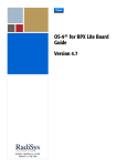
Version 1.2
Intelligent Products For A Smarter World
Copyright and Publication Information
Copyright ©2000 Microware Systems Corporation. All Rights Reserved. Reproduction of
this document, in part or whole, by any means, electrical, mechanical, magnetic, optical,
chemical, manual, or otherwise is prohibited, without written permission from Microware
Systems Corporation.
This manual reflects version 1.2 of Enhanced OS-9 for StrongARM.
Revision:
Publication date:
C
April 2000
Disclaimer
The information contained herein is believed to be accurate as of the date of publication.
However, Microware will not be liable for any damages including indirect or consequential,
from use of the OS-9 operating system, Microware-provided software, or reliance on the
accuracy of this documentation. The information contained herein is subject to change
without notice.
Reproduction Notice
The software described in this document is intended to be used on a single computer
system. Microware expressly prohibits any reproduction of the software on tape, disk, or
any other medium except for backup purposes. Distribution of this software, in part or
whole, to any other party or on any other system may constitute copyright infringements
and misappropriation of trade secrets and confidential processes which are the property of
Microware and/or other parties. Unauthorized distribution of software may cause damages
far in excess of the value of the copies involved.
For additional copies of this software/documentation, or if you have questions concerning
the above notice, please contact your OS-9 supplier.
Trademarks
OS-9, OS-9000, DAVID, and MAUI are registered trademarks of Microware Systems
Corporation. SoftStax, FasTrak, UpLink, and Hawk are trademarks of Microware Systems
Corporation. All other product names referenced herein are either trademarks or
registered trademarks of their respective owners.
Address
Microware Systems Corporation
1500 N.W. 118th Street
Des Moines, Iowa 50325
515-223-8000
2
Enhanced OS-9 for the GraphicsClient Board Guide
Ta bl e o f C o n t e n t s
Chapter 1: Installing and Configuring Enhanced OS-9 for StrongARM
11
11
11
12
12
13
15
16
17
19
20
23
25
26
27
Requirements and Compatibility
Host Hardware Requirements (PC Compatible)
Host Software Requirements (PC Compatible)
Target Hardware Requirements
Java Hardware Requirements
OS-9 for StrongARM Architecture
Configure Board Switch Settings
Installing the Flash Device
Connecting the Reference Board to the Host
Configuring the ATA Card
Creating and Configuring an OS-9 ROM Image
Connecting the Reference Board to an Ethernet Network (Optional)
Pinging the Reference Board
Creating a new OS-9 Coreboot Image in Flash Memory (Optional)
Making a Coreboot Image with an EPROM programmer
Chapter 2: Board Specific Considerations
30
34
34
35
35
36
36
37
38
9
29
Low-Level System Modules
Boot Options
Booting from FLASH
Booting from PCMCIA ATA Card
Booting from PCMCIA Ethernet Card
Booting over Serial Communications Port via kermit
Restart Booter
Break Booter
High-Level System Modules
Enhanced OS-9 for GraphicsClient Board Guide
3
38
39
39
39
40
40
40
41
41
41
41
41
42
43
43
43
44
44
44
45
45
45
45
45
46
46
46
46
46
48
55
57
58
4
CPU Support Modules
System Configuration Module
Interrupt Controller Support
Real Time Clock
Ticker
Abort Handler
Generic IO Support modules (File Managers)
Pipe Descriptor
RAM Disk Support
Descriptors for Use with RAM
Serial and Console Devices
Descriptors for Use with sc1100
Descriptors for use with sc16550
Descriptors for Use with scllio
PCMCIA Support for IDE Type Devices
Descriptors for Use with rb1003
PCMCIA Support for 3COM Ethernet card
Descriptors for Use with spe509_pcm
Network Configuration Modules
SMC91C94 Ethernet Support
Descriptor for Use with spe91c94
Network Configuration Modules
UCB1200 Support modules.
Descriptors for Use with spucb1200
Maui Graphical Support modules
Descriptors for Use with gx_sa1100
Descriptors for Use with sd_ucb1200
MAUI configuration modules
MAUI protocol modules
OS9 Vector Mappings
GraphicsClient GPIO Usage
GPIO Interrupt Polarity
Port Specific Utilities
Enhanced OS-9 for GraphicsClient Board Guide
65
Memory Remapping
Chapter 3: OS-9 ROM Image Overview
72
72
75
76
79
80
82
82
82
83
83
84
84
84
84
84
85
85
85
85
Types of ROM Images
Coreboot Image
ROMCore
Bootfile Image
Coreboot and Bootfile Image
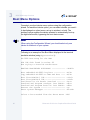
Boot Menu Options
Debuggers
Microware Hawk™
RomBug
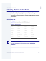
Including Options in Your Build
ROM Utility Set
RomBug in Bootfile (p2init)
User State Debugging Modules
Enable Disk Support Modules
Disk Utilities
SoftStax Support Modules
NFS Client Support Module
Keyboard Support
Mouse Support
User Modules
Appendix A: The Fastboot Enhancement
88
89
89
89
90
90
90
71
87
Overview
Implementation Overview
B_QUICKVAL
B_OKRAM
B_OKROM
B_1STINIT
B_NOIRQMASK
Enhanced OS-9 for GraphicsClient Board Guide
5
91
92
92
92
B_NOPARITY
Implementation Details
Compile-time Configuration
Runtime Configuration
Appendix B: MAUI Driver Descriptions
96
96
97
97
98
99
100
101
102
102
102
103
104
104
105
106
107
107
108
108
108
109
109
111
113
113
114
6
95
GraphicsClient Objects
MAUI objects
GX_SA1100 LCD Graphic Driver Specification
Board Ports
Device Capabilities
Display Resolution
Coding Methods
Viewport Complexity
Memory
Location
Build the Driver
Build the Descriptor
GX_SA1101 VGA Graphic Driver Specification
Device Capabilities
Display Resolution
Coding Methods
Viewport Complexity
Memory
Location
Build the Driver
Build the Descriptor
SD_UCB1200 Sound Driver Specification
Device Capabilities
Gain Capabilities Array
Sample Rates
Number of Channels
Encoding and Decoding Formats
Enhanced OS-9 for GraphicsClient Board Guide
115 SPUCB1200 driver for the UCB1200 Codec
115
Capabilities
115
Descriptors
116
UCB
116
Audio
116
Touch Screen
117
GPIO
118
Telecom
118
Supporting Modules
119 MP_UCB1200 MAUI Touch screen Protocol Module
119
Overview
119
Data Format
119
Data Filter
120
Raw Mode
120
cdb.touch
121
Compile Time Options
122
Calibration Application
122
Assumptions/Dependencies
122
Command Line Options
123
Coordination with Protocol Module
123
Compiling
Product Discrepancy Report
Enhanced OS-9 for GraphicsClient Board Guide
125
7
8
Enhanced OS-9 for GraphicsClient Board Guide
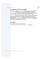
Chapter 1: Installing and Configuring
E nh a nc e d O S- 9 fo r St ro n g A R M
This chapter describes installing and configuring Enhanced OS-9 on
the ADS SA-1100 Microprocessor Reference Platform (GraphicsClient).
Before you begin, verify that the following actions have been performed:
•
You successfully installed the Enhanced OS-9 for StrongARM
CD-ROM onto your host PC.
•
You are familiar with your board’s features and capabilities.
•
You have followed the start-up procedure for your SA-1100
evaluation board as stated in the Graphics Client User’s Manual.
This chapter includes the following sections:
•
Requirements and Compatibility
•
OS-9 for StrongARM Architecture
•
Configure Board Switch Settings
•
Installing the Flash Device
•
Connecting the Reference Board to the Host
•
Configuring the ATA Card
•
Creating and Configuring an OS-9 ROM Image
•
Connecting the Reference Board to an Ethernet Network
(Optional)
•
Creating a new OS-9 Coreboot Image in Flash Memory
(Optional)
9
1
Installing and Configuring Enhanced OS-9 for StrongARM
More In
fo More
Informatio
n More Inf
ormation M
ore Inform
ation More
-6-
For More Information
The Graphics Client User’s Manual is provided by Applied Data
Systems, Inc. (ADS document #100110-40025). You can download a
copy of this document from www.flatpanels.com.
Note
These procedures can be performed with other StrongARM reference
platforms. You will need to modify the procedures as necessary for your
particular target platform.
10
Enhanced OS-9 for the GraphicsClient Board Guide
1
Installing and Configuring Enhanced OS-9 for StrongARM
Requirements and Compatibility
Host Hardware Requirements (PC Compatible)
Your host PC should have the following:
•
Windows 95, Windows 98, or Windows NT
•
A minimum of 32MB of free disk space (an additional 235MB of free
disk space is required to run PersonalJava Solution for OS-9)
•
An Ethernet network card
•
A PCMCIA card reader/writer
•
At least 16MB of RAM
Note
If you are a PersonalJava Solution for OS-9 licensee and you plan to
use the Java JCC to pre-load your Java classes, you may need as
much as 64MB of RAM. Refer to the document Using
JavaCodeCompact for a complete discussion of using the JCC.
Host Software Requirements (PC Compatible)
Your host PC should have a terminal emulation program (such as
Hyperterminal that comes with Microsoft Windows 95, Windows 98,
and Windows NT).
Enhanced OS-9 for the GraphicsClient Board Guide
11
1
Installing and Configuring Enhanced OS-9 for StrongARM
Target Hardware Requirements
Your reference board requires the following hardware:
•
Enclosure or chassis with power supply
•
A RS-232 null modem serial cable
•
LCD screen, keyboard, and mouse (for use with mwMAUI)
Java Hardware Requirements
Your reference board must have the following to run PersonalJava
Solution for OS-9:
12
•
16MB of RAM
•
4MB of FLASH (Boot)
•
LCD Display
Enhanced OS-9 for the GraphicsClient Board Guide
1
Installing and Configuring Enhanced OS-9 for StrongARM
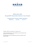
OS-9 for StrongARM Architecture
The source and example code and makefiles for Enhanced OS-9 for
StrongARM are located in the following directory. The directory
structure is shown in Figure 1-1.
\mwos\OS9000\ARMV4\PORTS\GRAPHICSCLIENT\
Figure 1-1 OS-9 for StrongARM Directories
BOOTS
CMDS
BOOTOBJS
INIT
DD
MAUI
CDB
INSTALL
PCF
PCMCIA
RB1003
PICLIB
DESC
NODISK
GX_SA1100
BMP
RAM
INI
MP_MSPTR
PIPE
LIB
RB1003
PORTBOOT
MP_XTKBD
HOST3
SC1110
MP_UCB1200
SPF
SC16550
TOUCH_CAL
WINDOWS
SCLLIO
SYSTEMS
INITS
PORTBOOT
MAUI
ROM
SPF
Enhanced OS-9 for the GraphicsClient Board Guide
13
1
Installing and Configuring Enhanced OS-9 for StrongARM
Figure 1-1 OS-9 for StrongARM Directories (continued)
RBF
ROM
SCF
SPF
SYSMODS
UTILS
CNFGDATA
RAM
SC1100
ETC
RTC
ABORT
SC16550
SP91C94
TICKER
PCMCIA
SCLLIO
SPE509
CNFGFUNC
RB1003
COMMCNFG
CONSCNFG
IDE
IO1100
SPUCB120
LLCIS
LLE509
PORTMENU
ROMCORE
TIMR1100
USEDEBUG
14
Enhanced OS-9 for the GraphicsClient Board Guide
1
Installing and Configuring Enhanced OS-9 for StrongARM
Configure Board Switch Settings
Set the jumpers according to the GraphicsClient User’s Manual
supplied by Applied Data Systems (ADS document # 100110-40025).
Note
In most cases you can use the default factory jumper settings.
Enhanced OS-9 for the GraphicsClient Board Guide
15
1
Installing and Configuring Enhanced OS-9 for StrongARM
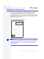
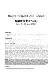
Installing the Flash Device
The first stage in configuring your reference board is to install the
pre-loaded FLASH device included in your Enhanced OS-9 for
StrongARM package. This device includes a coreboot system that has
been pre-configured to get your board up and running quickly. Install the
FLASH device in socket U22.
Figure 1-2 Installing the Flash Devices
PCMCIA Socket
U22
Note
If you need to reprogram the flash devices or create new flash devices,
see the Creating a new OS-9 Coreboot Image in Flash Memory
(Optional) section.
16
Enhanced OS-9 for the GraphicsClient Board Guide
1
Installing and Configuring Enhanced OS-9 for StrongARM
Connecting the Reference Board to the Host
Connect an RS-232 null modem cable from the reference board to the
serial port of a Windows 95, Windows 98, or Windows NT system.
Step 1.
Connect the serial cable to the J10 connector (or the DB9 connector
that connects to J10) on the reference board. The J10 connector is the
SA1100 serial port 3 (SP3).
Step 2.
Connect the other end of the serial cable to the Host PC.
Step 3.
On the Windows desktop, click on the Start button and select
Programs -> Accessories -> Hyperterminal.
Step 4.
Click the Hypertrm icon and enter a name for your Hyperterminal
session.
Step 5.
Select an icon for the new Hyperterminal session. A new icon is created
with the name of your session associated with it. The next time you
want to establish the same session, follow the directions in Step 3 and
look for the icon you created in Step 4.
Step 6.
Click OK
Step 7.
In the Phone Number dialog, go to the Connect Using box, and select the
communications port to be used to connect to the reference board.
The port selected is the same port that you connected to the serial
cable from the reference board.
Step 8.
Click OK
Step 9.
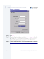
In the Port Settings tab, enter the following settings:
Bits per second = 19200
Data Bits = 8
Parity = None
Stop bits = 1
Flow control = XOn/XOff
Enhanced OS-9 for the GraphicsClient Board Guide
17
1
Installing and Configuring Enhanced OS-9 for StrongARM
Figure 1-3 Port Settings
Step 10. Click OK.
Step 11. Go to the Hyperterminal menu and select Call -> Connect from the
pull-down menu to establish your terminal session with the reference
board. If you are connected, the bottom left of your Hyperterminal
screen will display the word connected.
Step 12. Turn on the reference board. The OS-9 bootstrap message is displayed.
18
Enhanced OS-9 for the GraphicsClient Board Guide
1
Installing and Configuring Enhanced OS-9 for StrongARM
Configuring the ATA Card
You can use your ATA card to validate that your reference board is
operational without requiring the connection to the host machine:
To configure the ATA card:
Step 1.
From a DOS prompt on the host machine, navigate to the following
directory:
MWOS\OS9000\ARMV4\PORTS\GRAPHICSCLIENT\BOOTS\SYSTEMS\PORTBOOT
and run os9make.
Step 2.
On the host machine, copy the files located in the following directory:
MWOS\OS9000\ARMV4\PORTS\GRAPHICSCLIENT\BOOTS\SYSTEMS\PORTBOOT\os9kboot
into the root directory to the ATA card
Step 3.
Install the card in the single PCMCIA socket on the reference board
Step 4.
Turn on the reference board. After a few seconds an OS-9 shell prompt
will appear on your terminal.
Enhanced OS-9 for the GraphicsClient Board Guide
19
1
Installing and Configuring Enhanced OS-9 for StrongARM
Creating and Configuring an OS-9 ROM Image
The OS-9 ROM image enables booting from PCMCIA IDE type cards.
Use the Configuration Wizard to create an OS-9ROM Image to save in
the root directory of the PCMCIA card. The Configuration Wizard was
installed on your host PC during the Enhanced OS-9 for StrongARM
installation process.
Note
Enhanced OS-9 for StrongARM also supports ATA Flash cards.
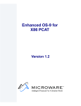
To use the Configuration Wizard, perform the following steps:
Step 1.
Click the Start button on the Windows desktop.
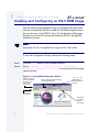
Step 2.
Select Programs -> Enhanced OS-9 for StrongARM ->
Microware Configuration Wizard. You should see the following
opening screen:
Figure 1-4 StrongARM Configuration Wizard
Select the directory
where your MWOS
file structure is
installed on
your Host PC
Select Advanced Mode for modifying
an existing ROM image
Select Use Wizard
when building a
ROM image for the
first time
Select the
board model
Enter the file
name for the
build you
are creating
20
Enhanced OS-9 for the GraphicsClient Board Guide
1
Installing and Configuring Enhanced OS-9 for StrongARM
Step 3.
Select the path where the MWOS directory structure is located from the
MWOS location button.
Step 4.
Select the target board from the Port Selection pull-down menu.
Step 5.
Name the ROM Image in the Configuration Name field.
Step 6.
Select Advanced Mode and click OK. The Main Configuration window
is displayed.
Step 7.
Select Configure -> Bootfile -> NetWork Configuration.
Note
If you intend to use the Target board across a network, you need to
configure the Ethernet settings. Be sure the Enable SoftStax radio
button is selected in the SoftStax Setup tab.
Use the Configuration Wizard help for information on the settings.
Step 8.
Leave the other options at the default settings.
Step 9.
Select Configure -> Build Image to display the Master Builder
screen.
Step 10. Click Build. This will build a boot image that can be placed on the
PCMCIA card.
Step 11. Insert the PCMCIA IDE card into the PCMCIA slot of your computer.
Step 12. Click Save As to save the file os9kboot to the root directory of the
PCMCIA IDE card.
Step 13. Turn off the power to the reference board.
Enhanced OS-9 for the GraphicsClient Board Guide
21
1
Installing and Configuring Enhanced OS-9 for StrongARM
!
WARNING
Inserting and removing a PCMCIA card with the power on is not
supported in this release. Damage may occur to the PCMCIA card if it is
inserted or removed while power is applied to the board.
Step 14. Remove the PCMCIA IDE card from the computer.
Step 15. Position the PCMCIA card so that the end with the connector holes is
facing the PCMCIA socket and the label is facing up.
Step 16. Slide the card into the socket of the reference board until the card
snaps onto the connector pins and the eject button pops out.
Note
The GraphicsClient design does not provide enough current for the
TypeIII PCMCIA (double height).
Step 17. Apply power to the board. The reference board will boot from the IDE
PCMCIA card and you should see the “$” prompt.
22
Enhanced OS-9 for the GraphicsClient Board Guide
1
Installing and Configuring Enhanced OS-9 for StrongARM
Connecting the Reference Board to an
Ethernet Network (Optional)
Enhanced OS-9 for StrongARM supports using the onboard
SMC91C94 or a 3COM Etherlink III - LAN PC Card for mwSoftStax
TCP/IP connections. Also, Enhanced OS-9 for StrongARM provides
system level support for telnet, FTP, and NFS.
To use Ethernet networking, you must create a bootfile that has the
Ethernet options enabled and insert an Ethernet PCMCIA card into the
reference board if you choose to use a PCMCIA Ethernet card.
Step 1.
Click the Start button on the Windows desktop.
Step 2.
Select Programs -> Enhanced OS-9 StrongARM ->
Microware Configuration Wizard. You should see the opening
screen.
Step 3.
Click OK. The configuration screen is displayed.
Step 4.
Select Configure -> Bootfile -> NetWork Configuration.
The network options dialog box appears.
Step 5.
Change the network settings as needed. See the Configuration Wizard
help for more information on the network settings.
Step 6.
Create a new Bootfile by following the directions in the Creating and
Configuring an OS-9 ROM Image section.
Step 7.
Turn off the power to the reference board.
!
WARNING
Inserting and removing a PCMCIA card with the power on is not
supported in this release. Damage may occur to the PCMCIA card if it is
inserted or removed while power is applied to the board.
Step 8.
Position the PCMCIA IDE card so that the end with the PCMCIA female
connector is facing PCMCIA socket and the label is facing up.
Enhanced OS-9 for the GraphicsClient Board Guide
23
1
Installing and Configuring Enhanced OS-9 for StrongARM
Slide the PCMCIA IDE card into the socket until the card snaps onto the
pins and the eject button pops out.
Step 9.
Connect the 10 Base T connector into J9 if using the onboard Ethernet.
or
Position the Ethernet PCMCIA card so that the end with the PCMCIA
female connector is facing the PCMCIA socket and the label is facing
up.
Slide the PCMCIA Ethernet card into the socket until the card snaps
onto the pins and the eject button pops out.
Step 10. Restart your reference board.
Step 11. Test the Ethernet connection by pinging the reference board.
If the ping operation fails, you will have to check the following items:
•
is the board connected to a live Ethernet port?
•
is the Ethernet cable defective?
•
are the network settings for the reference board correct?
Note
There is only one PCMCIA socket on the ADS Graphics Client board. In
order to use the 3COM PCMCIA Ethernet card, you must first burn an
Ethernet enabled OS-9 ROM image into the 16MB on-board Flash. See
the pflash utility for more information.
Another option is to create a new EEPROM part with bootp, along with
an appropriate server.
24
Enhanced OS-9 for the GraphicsClient Board Guide
1
Installing and Configuring Enhanced OS-9 for StrongARM
Pinging the Reference Board
Windows 95, Windows 98, and Windows NT include a Ping command
that can be used to test the Ethernet connection for the reference
board.
Step 1.
Go to the DOS prompt.
Step 2.
Type ping <IP Address>.
The IP Address is the address you assigned to the evaluation board
in either the Coreboot module or the Bootfile module. The address is
typed without the <> brackets.
If the ping was successful, you will see the following response:
Reply from <IP Address>: bytes=xx time =xms TTL= xx
If the ping was unsuccessful, you will see the following response:
Request timed out.
Enhanced OS-9 for the GraphicsClient Board Guide
25
1
Installing and Configuring Enhanced OS-9 for StrongARM
Creating a new OS-9 Coreboot Image in Flash
Memory (Optional)
If you want to use ROM Ethernet services such as System State
Debugging, you must create a new coreboot image. The coreboot
image that was shipped with the reference board does not allow you to
perform System State Debugging because the IP address in Flash
ROM is set to “0.0.0.0”. You can create the coreboot image with an
EPROM programmer.
Note
Re-creating the Coreboot image is required only when system state
debugging is desired.
26
Enhanced OS-9 for the GraphicsClient Board Guide
1
Installing and Configuring Enhanced OS-9 for StrongARM
Making a Coreboot Image with an EPROM programmer
This section describes creating the Coreboot Image. When you are
done creating the coreboot image, please refer to your EPROM
programmer’s instructions to learn how to load the Coreboot image into
the EPROM.
Step 1.
Click the Start button on the Windows desktop.
Step 2.
Select Programs -> Enhanced OS-9 StrongARM ->
Microware Configuration Wizard. You should see the following
opening screen:
Figure 1-5 StrongARM Configuration Wizard
Select the directory
where your MWOS
file structure is
installed on
your Host PC
Select Advanced Mode for modifying
an existing ROM image
Select Use Wizard
when building a
ROM image for the
first time
Select the
board model
Enter the file
name for the
build you
are creating
Step 3.
Give the boot image a name in the Configuration Name field.
Step 4.
Select Advanced Mode and click OK. The configuration screen is
displayed.
Step 5.
Make any necessary changes to the coreboot settings.
Step 6.
Select Configure->Build Image to display the Master Builder
screen.
Step 7.
Select the Coreboot Only Image setting and click Build.
Enhanced OS-9 for the GraphicsClient Board Guide
27
1
Installing and Configuring Enhanced OS-9 for StrongARM
Step 8.
Click Save As to save the coreboot image to a directory of your
choosing. If you do not have that directory on the drive, you can create
it.
Step 9.
Transfer the coreboot image to the EPROM with the EPROM
programmer. You will need to follow the documentation for the EPROM
programmer to complete this step.
28
Enhanced OS-9 for the GraphicsClient Board Guide
C h a p t e r 2 : B o a rd S p e c i f i c
Considerations
This chapter contains information that is specific to the INTEL SA-1100
Microprocessor Reference Platform (GraphicsClient) reference board. It
includes the following sections:
More In
fo More
Informatio
n More Inf
ormation M
ore Inform
ation More
-6-
•
Low-Level System Modules
•
Boot Options
•
High-Level System Modules
•
OS9 Vector Mappings
•
GraphicsClient GPIO Usage
•
Port Specific Utilities
•
Memory Remapping
For More Information
For general information on porting OS-9, see the OS-9 Porting Guide.
29
2
Board Specific Considerations
Low-Level System Modules
More In
fo More
Informatio
n More Inf
ormation M
ore Inform
ation More
-6-
For More Information
For a complete list of OS-9 modules common to all boards, see the
OS-9 Device Descriptor and Configuration Module Reference
manual.
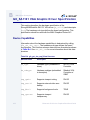
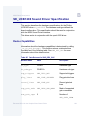
The following low-level system modules are tailored specifically for the
ADS SA1100 GraphicsClient platform. The functionality of these
modules can be altered through changes to the configuration data
module (cnfgdata). Table 2-1 provides a list and brief description of
the modules.
These modules can be found in the following directory:
MWOS/OS9000/ARMV4/PORTS/GRAPHICSCLIENT/CMDS/BOOTOBJS/ROM
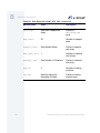
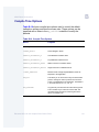
Table 2-1 GraphicsClient-Specific Low-Level System Modules
30
Module Name
Description
cnfgdata
Contains the low-level configuration data.
cnfgfunc
Provides access services to cnfgdata data.
commcnfg
Inits communication port defined in cnfgdata.
conscnfg
Inits console port defined in cnfgdata.
ide
IDE boot support module. PCMCIA compatible.
io1100
Provides polled serial driver support for the low-level
system.
Enhanced OS-9 for the GraphicsClient Board Guide
2
Board Specific Considerations
Table 2-1 GraphicsClient-Specific Low-Level System Modules
Module Name
Description
llcis
Inits the PCMCIA interface including cards.
lle509
Provides low-level ethernet services via 3COM
PCMCIA card.
portmenu
Inits booters defined in the cnfgdata.
romcore
Board specific initialization code.
splash
Provides way to init LCD screen with a compressed
image.
tmr1_1100
Provides low-level timer services via time base
register.
usedebug
Inits low-level debug interface to RomBug, SNDP, or
none.
The following low-level system modules provide generic services for
OS9000 Modular ROM. Table 2-2 provides a list and brief description of
the modules.
These modules can be found in the following directory:
MWOS/OS9000/ARMV3/CMDS/BOOTOBJS/ROM
Table 2-2 Generic Services Low-Level System Modules
Module Name
Description
bootsys
Booter registration service module.
console
Provides console services.
Enhanced OS-9 for the GraphicsClient Board Guide
31
2
Board Specific Considerations
Table 2-2 Generic Services Low-Level System Modules (continued)
32
Module Name
Description
dbgentry
Inits debugger entry point for system use.
dbgserve
Provides debugger services.
excption
Provides low-level exception services.
flshcach
Provides low-level cache management services.
hlproto
Provides user level code access to protoman.
llbootp
Booter which provides bootp services.
llip
Provides low-level IP services.
llslip
Provides low-level SLIP services.
lltcp
Provides low-level TCP services.
lludp
Provides low-level UDP services.
llkermit
Booter which uses kermit protocol.
notify
Provides state change information for use with LL
and HL drivers.
override
Booter which allows choice between menu and auto
booters.
parser
Provides argument parsing services.
pcman
Booter which reads MS-DOS file system.
protoman
Protocol management module.
Enhanced OS-9 for the GraphicsClient Board Guide
2
Board Specific Considerations
Table 2-2 Generic Services Low-Level System Modules (continued)
Module Name
Description
restart
Booter which cause a soft reboot of system.
romboot
Booter which allows booting from ROM.
rombreak
Booter which calls the installed debugger.
rombug
Low-level system debugger.
sndp
Provides low-level system debug protocol.
srecord
Booter which accepts S-Records.
swtimer
Provides timer services via software loops.
Enhanced OS-9 for the GraphicsClient Board Guide
33
2
Board Specific Considerations
Boot Options
Following are the default boot options for the reference board. You can
select these by hitting the space bar when the Now Trying to Override
Autobooters message appears on the console port when booting.
You can configure these booters by altering the default.des file at
the following location:
MWOS/OS9000/ARMV4/PORTS/GRAPHICSCLIENT/ROM
Booters can be configured to be either menu or auto booters. The auto
booters automatically try and boot in order from each entry in the auto
booter array. Menu booters from the defined menu booter array are
chosen interactively from the console command line after getting the
boot menu.
Booting from FLASH
When the romcnfg.h has a ROM search list defined the options ro
and lr appear in the boot menu. If no search list is defined N/A appears
in the boot menu. If an OS9 bootfile is programmed into flash in the
address range defined in ports default.des file the system can boot and
run from flash.
34
ro
rom boot—the system runs from the FLASH
bank.
lr
load to ram—the system copies the flash image
into ram and runs from there.
Enhanced OS-9 for the GraphicsClient Board Guide
2
Board Specific Considerations
Booting from PCMCIA ATA Card
The system can boot from a PC formatted PCMCIA hard card which
resides in the PCMCIA slot.
ide0
The file os9kboot is searched for in slot 0. If
found it is copied to system RAM and runs from
there.
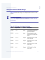
Booting from PCMCIA Ethernet Card
The system can boot using the BootP protocol using an Ethernet card
and eb option.
eb
Ethernet boot—a PCMCIA card which supports
ethernet will use the bootp protocol to transfer
in a bootfile into RAM and the systems runs
from there.
Enhanced OS-9 for the GraphicsClient Board Guide
35
2
Board Specific Considerations
Booting over Serial Communications Port via kermit
The system can down-load a bootfile in binary form over its serial
communication port at 115200 using the kermit protocol. The speed of
this transfer depends of the size of the bootfile, but expect at least a 3
minute wait, dots will show the progress of the boot. The
communications port is located at header J7 and uses the SA1100’s
SP1 UART.
ker
kermit boot—The os9kboot file is sent via the
kermit protocol into system RAM and runs from
there.
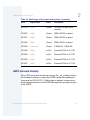
Restart Booter
The restart booter allows a way to restart the bootstrap sequence.
q
36
quit—quit and attempt to restart the booting
process.
Enhanced OS-9 for the GraphicsClient Board Guide
2
Board Specific Considerations
Break Booter
The break booter allows entry to the system level debugger (if one
exists). If the debugger is not in the system the system will reset.
break
break—break and enter the system level
debugger rombug.
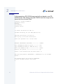
Example boot session and message.
OS-9000 Bootstrap for the ARM
ATA IDE disk found in socket 00
Now trying to Override autobooters.
BOOTING PROCEDURES AVAILABLE ------------- <INPUT>
Boot embedded OS-9000 in-place ----------Copy embedded OS-9000 to RAM and boot ---Boot from PCMCIA-1 IDE ------------------Boot from PCMCIA-0 IDE ------------------Load bootfile via kermit Download -------Restart the System ----------------------Enter system debugger --------------------
<N/A>
<N/A>
<ide1>
<ide0>
<ker>
<q>
<break>
Select a boot method from the above menu: ide0
Wait for IDE drive ready.
IDE Model
:
ATA_FLASH
Number Heads
: 0x0002
Total Cylinders
: 0x03d8
Sectors Per Track
: 0x0020
Checking Partitions
Fat Type
File Name
File Size
Start Cluster
Reading Bootfile....
:
:
:
:
:
0
0x16
OS9KBOOT
0x000fdeb0
0x00003a57
Boot Address
Boot Size
: 0xc002c850
: 0x000fdeb0
OS-9000 kernel was found.
A valid OS-9000 bootfile was found.
$
Enhanced OS-9 for the GraphicsClient Board Guide
37
2
Board Specific Considerations
High-Level System Modules
The following OS-9 system modules are tailored specifically for your
Intel SA1100 GraphicsClient board and peripherals. Unless otherwise
specified, each module is located in a file of the same name in the
following directory:
MWOS/OS9000/ARMV4/PORTS/GRAPHICSCLIENT/CMDS/BOOTOBJS
CPU Support Modules
These files are located in the following directory:
MWOS/OS9000/ARMV4/CMDS/BOOTOBJS
38
kernel
The kernel provides all basic services for the
OS-9 system.
cache
Provides cache control for the CPU cache
hardware. The cache module is in the file
cach1100.
fpu
Provides software emulation for floating point
instructions.
ssm
The System Security Module provides support
for the Memory Management Unit (MMU) on
the CPU.
vectors
Provides interrupt service entry and exit code.
The vectors module is found in the file
vect110.
Enhanced OS-9 for the GraphicsClient Board Guide
2
Board Specific Considerations
System Configuration Module
These files are located in the following directory:
MWOS/OS9000/ARMV4/PORTS/GRAPHICSCLIENT/CMDS/BOOTOBJS/INITS
init
Descriptor module with high level system
initialization information.
nodisk
Same as init, but used in a disk-less system.
Interrupt Controller Support
This module provides extensions to the vectors module by mapping the
single interrupt generated by an interrupt controller into a range of
pseudo vectors which are recognized by OS-9 as extensions to the
base CPU exception vectors.
More In
fo More
Informatio
n More Inf
ormation M
ore Inform
ation More
-6-
For More Information
The mappings are described in the OS9 Vector Mappings section.
irq1100
P2module that provides interrupt acknowledge
and dispatching support for the SA1100 pic.
irqtc
P2module that provides interrupt acknowledge
and dispatching support for the GraphicsClient
pic (vector range 0xB1-0xC0).
Real Time Clock
rtc1100
Driver that provides OS-9 access to the
SA1100 on-board real time clock.
Enhanced OS-9 for the GraphicsClient Board Guide
39
2
Board Specific Considerations
Ticker
tk1100
Driver that provides the system ticker based on
the SA1100 Operating System Timer.
Abort Handler
abort
P2module which provides a way to enter the
system-state debugger via the GPIO[0]
interrupt triggered by GraphicsClient switch S1,
1.
Generic IO Support modules (File Managers)
These files are located in the following directory:
MWOS/OS9000/ARMV3/CMDS/BOOTOBJS
40
ioman
Provides generic io support for all IO device
types.
scf
Provides generic character device management
functions.
rbf
Provides generic block device management
functions for OS-9 specific format.
pcf
Provides generic block device management
functions for MS-DOS FAT format.
spf
Provides generic protocol device management
function support.
mfm
Provides generic graphics device support for
MAUI.
pipeman
Provides a memory FIFO buffer for
communication.
Enhanced OS-9 for the GraphicsClient Board Guide
2
Board Specific Considerations
Pipe Descriptor
This file is located in the following directory:
MWOS/OS9000/ARMV4/PORTS/GRAPHICSCLIENT/CMDS/BOOTOBJS/DESC
Pipeman descriptor that provides a RAM based
FIFO which can be used for process
communication.
pipe
RAM Disk Support
RBF driver which provides a RAM based virtual
block device.
ram
Descriptors for Use with RAM
These files are located in the following directory:
MWOS/OS9000/ARMV4/PORTS/GRAPHICSCLIENT/CMDS/BOOTOBJS/DESC/RAM
r0
RBF descriptor which provides access to a ram
disk.
r0.dd
Same as r0 except with module name dd (for
use as the default device).
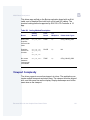
Serial and Console Devices
sc1100
SCF driver which provides serial support the
SA1100’s SP1 and SP3 ports when configured
as UARTS.
Descriptors for Use with sc1100
term1/t1
Descriptor modules for
use with sc1100 and SP1.
GraphicsClient Board header: J7
Enhanced OS-9 for the GraphicsClient Board Guide
41
2
Board Specific Considerations
term3/t3
Default Baud Rate:
19200
Default Parity:
None
Default Data Bits:
8
Default Handshake:
Software
Descriptor modules for use
with sc1100 and SP3.
GraphicsClient Board header: J2
sc16550
Default Baud Rate:
115200
Default Parity:
None
Default Data Bits:
8
Default Handshake:
Software
SCF driver which provides serial supports a
16550 compatible modem card.
Descriptors for use with sc16550
t0m
Descriptor modules for use with the external
PCMCIA card
sc16550
GraphicsClient Board header: J11 PCMCIA
slot
42
Default Baud Rate:
9600
Default Parity:
None
Default Data Bits:
8
Default Handshake:
Software
Enhanced OS-9 for the GraphicsClient Board Guide
2
Board Specific Considerations
Descriptors for Use with scllio
vcons/term
Descriptor modules for use with scllio in
conjunction with a low-level serial driver. Port
configuration and set up follows what is
configured in cnfgdata for the console port. It is
possible for scllio to communicate with a true
low-level serial device driver like io1100, or with
an emulated serial interface provided by
iovcons. See the OEM manual for more
information.
PCMCIA Support for IDE Type Devices
rb1003
RBF/PCF driver that provides driver support for
IDE/EIDE devices. This driver is used to provide
disk support for PCMCIA ATA FLASH.
Descriptors for Use with rb1003
hc1/hc1fmt and hc1.dd
RBF Descriptor modules for use\
with PCMCIA slot #0
GraphicsClient Board header:J11
hc1fmt:
format enabled
hc1.dd:
module name of dd
mhc1/mhc1.dd
PCF Descriptor modules for use with PCMCIA
slot #0
GraphicsClient Board header:J11
mhc1.dd:
Enhanced OS-9 for the GraphicsClient Board Guide
module name of dd
43
2
Board Specific Considerations
PCMCIA Support for 3COM Ethernet card
These files are located in the following directory:
MWOS/OS9000/ARMV4/PORTS/GRAPHICSCLIENT/CMDS/BOOTOBJS/SPF
spe509_pcm
SPF driver to support ethernet for a 3COM
EtherLink III PCMCIA card.
Descriptors for Use with spe509_pcm
spe30
SPF descriptor module for use with PCMCIA
slot #0 (J11)
Network Configuration Modules
inetdb/inetdb2/rpcdb
44
Enhanced OS-9 for the GraphicsClient Board Guide
2
Board Specific Considerations
SMC91C94 Ethernet Support
These files are located in the following directory:
MWOS/OS9000/ARMV4/PORTS/GRAPHICSCLIENT/CMDS/BOOTOBJS/SPF
spe91c94
SPF driver to support ethernet for the
SMC91C94 chip.
Descriptor for Use with spe91c94
spsm0
SPF descriptor module for use with
SMC91C94 at J9.
Network Configuration Modules
inetdb/inetdb2/rpcdb
UCB1200 Support modules.
These files are located in the following directory:
MWOS/OS9000/ARMV4/PORTS/GRAPHICSCLIENT/CMDS/BOOTOBJS/SPF
spucb1200
SPF driver that supports the on-board Phillips
UCB1200 chip. This device communicates to
the SA1100 over SP4 using MCP.
Descriptors for Use with spucb1200
ucb
SPF descriptor module that provides access to
UCB1200.
ucb_touch
SPF descriptor module used with the touch
screen.
Enhanced OS-9 for the GraphicsClient Board Guide
45
2
Board Specific Considerations
Maui Graphical Support modules
These files are located in the following directory:
MWOS/OS9000/ARMV4/PORTS/GRAPHICSCLIENT/CMDS/BOOTOBJS/MAUI
gx_sa1100
MFM MAUI driver module with support for the
GraphicsClient LCD panel.
Descriptors for Use with gx_sa1100
gfx
MFM MAUI descriptor module for
GraphicsClient LCD.
sd_ucb 1200
MFM MAUI driver module that provides
PCM/mu-law sound support via the ucb1200.
Descriptors for Use with sd_ucb1200
snd
MFM MAUI descriptor module for UCB1200
sound functions.
MAUI configuration modules
cdb
MAUI configuration data base module.
cdb_ptr
Serial mouse configuration data base module.
cdb_touch
Touch screen configuration data base module.
MAUI protocol modules
46
mp_kybrd
Keyboard protocol module
mp_msptr
Serial mouse protocol module.
mp_ucb1200
ucb1200 protocol module.
Enhanced OS-9 for the GraphicsClient Board Guide
2
Board Specific Considerations
More In
fo More
Informatio
n More Inf
ormation M
ore Inform
ation More
-6-
For More Information
The MAUI drivers are described in more detail in Appendix B: MAUI
Driver Descriptions.
Enhanced OS-9 for the GraphicsClient Board Guide
47
2
Board Specific Considerations
OS9 Vector Mappings
This section contains the vector mappings for the OS9 GraphicsClient
implementation of the SA1100.
The ARM standard defines exceptions 0x0-0x8. The OS-9 system
maps these 1-1. External interrupts from vector 0x6 are expanded to
the virtual vector rage shown below by the irq1100 module.
Note
Vectors can be virtually remapped from a ROM at physical address 0,
into DRAM at virtual address 0. This speeds up interrupt response time
and is enabled by defining the first cache list entry as a sub 1 Meg size.
More In
fo More
Informatio
n More Inf
ormation M
ore Inform
ation More
-6-
For More Information
See the 1100 hardware documentation for more information on
individual sources.
Table 2-3 and Table 2-4 show the OS9 IRQ assignment for the
GraphicsClient SA1100 board.
Table 2-3 IRQ Assignments and ARM Functions
48
OS9 IRQ #
ARM Function
0x0
Processor Reset
0x1
Undefined Instruction
0x2
Software Interrupt
Enhanced OS-9 for the GraphicsClient Board Guide
2
Board Specific Considerations
Table 2-3 IRQ Assignments and ARM Functions (continued)
OS9 IRQ #
ARM Function
0x3
Abort on Instruction Prefetch
0x4
Abort on Data Access
0x5
Unassigned/Reserved
0x6
External Interrupt
0x7
Fast Interrupt
0x8
Alignment error
Table 2-4 IRQ Assignments and SA1100 Specific Functions
OS9 IRQ #
SA1100 Specific Function (pic)
0x40
GPIO[0] Edge Detect (IRQ Input from GraphicsClient
PIC.)
0x41
GPIO[1] Edge Detect
0x42
GPIO[2] Edge Detect
0x43
GPIO[3] Edge Detect
0x44
GPIO[4] Edge Detect
0x45
GPIO[5] Edge Detect
0x46
GPIO[6] Edge Detect
Enhanced OS-9 for the GraphicsClient Board Guide
49
2
Board Specific Considerations
Table 2-4 IRQ Assignments and SA1100 Specific Functions (continued)
50
OS9 IRQ #
SA1100 Specific Function (pic)
0x47
GPIO[7] Edge Detect
0x48
GPIO[8] Edge Detect
0x49
GPIO[9] Edge Detect
0x4a
GPIO[10] Edge Detect
0x4b
OR of GPIO edge detects 27 - 11
0x4c
LCD controller service request
0x4d
UDC service request (0)
0x4e
SDLC service request (1a)
0x4f
UART service request (1b) (SP1)
0x50
UART/HSSP service request (2)
0x51
UART service request (3) (SP3)
0x52
MCP service request (4a)
0x53
SSP service request (4b)
0x54
DMA controller channel 0
0x55
DMA controller channel 1
0x56
DMA controller channel 2
0x57
DMA controller channel 3
Enhanced OS-9 for the GraphicsClient Board Guide
2
Board Specific Considerations
Table 2-4 IRQ Assignments and SA1100 Specific Functions (continued)
OS9 IRQ #
SA1100 Specific Function (pic)
0x58
DMA controller channel 4
0x59
DMA controller channel 5
0x5a
OS timer 0
0x5b
OS timer 1
0x5c
OS timer 2
0x5d
OS timer 3
0x5e
One Hz clock tick
0x5f
RTC als alarm register
0x60
GPIO[11] Edge Detect (the vector 0x4b OR is broken
out here to make each one distinct)
0x61
GPIO[12] Edge Detect
0x62
GPIO[13] Edge Detect
0x63
GPIO[14] Edge Detect
0x64
GPIO[15] Edge Detect
0x65
GPIO[16] Edge Detect
0x66
GPIO[17] Edge Detect
0x67
GPIO[18] Edge Detect
0x68
GPIO[19] Edge Detect
Enhanced OS-9 for the GraphicsClient Board Guide
51
2
Board Specific Considerations
Table 2-4 IRQ Assignments and SA1100 Specific Functions (continued)
OS9 IRQ #
SA1100 Specific Function (pic)
0x69
GPIO[20] Edge Detect
0x6a
GPIO[21] Edge Detect
0x6b
GPIO[22] Edge Detect
0x6c
GPIO[23] Edge Detect
0x6d
GPIO[24] Edge Detect
0x6e
GPIO[25] Edge Detect
0x6f
GPIO[26] Edge Detect
0x70
GPIO[27] Edge Detect
Table 2-5 shows the GraphicsClient Pic functions.
Table 2-5 GraphicsClient Pic Functions
52
OS9 IRQ #
GraphicsClient Function (GraphicsClient Pic)
0xb1
RESERVED
0xb2
RESERVED
0xb3
RESERVED
0xb4
RESERVED
0xb5
RESERVED
0xb6
RESERVED
Enhanced OS-9 for the GraphicsClient Board Guide
2
Board Specific Considerations
Table 2-5 GraphicsClient Pic Functions (continued)
OS9 IRQ #
GraphicsClient Function (GraphicsClient Pic)
0xb7
PCMCIA slot 0 Ready/IRQ
0xb8
RESERVED
0xb9
UCB 1200
0xba
SMC 91C94 Ethernet
0xbb
RESERVED
0xbc
PCMCIA Card A detect
0xbd
RESERVED
0xbe
Board Switch
0xbf
IRQ SSP
0xc0
IRQ BAT FAULT
Enhanced OS-9 for the GraphicsClient Board Guide
53
2
Board Specific Considerations
Note
Fast Interrupt Vector (0x7)
The ARM4 defined fast interrupt (FIQ) mapped to vector 0x7 is handled
differently by the OS-9 interrupt code and can not be used as freely as
the external interrupt mapped to vector 0x6. To make fast interrupts as
quick as possible for extremely time critical code, no context information
is saved on exception and FIQs are never masked. This requires any
exception handler to save and restore its necessary context if the FIQ
mechanism is to be used. This requirement means that a FIQ handler’s
entry and exit points must be in assembly, as the C compiler will make
assumptions about context. In addition, no system calls are possible
unless a full C ABI context save has been done first. The OS-9 IRQ
code for the SA1100 has assigned all interrupts as normal external
interrupts and the user must re-define a source as an FIQ to make use
of this feature.
54
Enhanced OS-9 for the GraphicsClient Board Guide
2
Board Specific Considerations
GraphicsClient GPIO Usage
Table 2-6 shows GPIO usage of the GraphicsClient board in an OS9
system.
More In
fo More
Informatio
n More Inf
ormation M
ore Inform
ation More
-6-
For More Information
See the ADS Graphics Client User’s Manual for available alternate
pin functions.
Table 2-6 GPIO Usage of the GraphicsClient Board
GPIO
Signal Name
Direct
Description
GPIO0
/IRQ
Input
Falling edge interrupt from
external peripheral
GPIO1
SWITCH
Input
External signal to wake
processor up during sleep
mode.
GPIO2
GREEN3
Output
LCD Green bit 3 in 16 bit
color mode=20
GPIO3
GREEN4
Output
LCD Green bit 4 in 16 bit
color mode
GPIO4
GREEN5
Output
LCD Green bit 5 in 16 bit
color mode
GPIO5
RED0
Output
LCD Red bit 0 in 16 bit
color mode
Enhanced OS-9 for the GraphicsClient Board Guide
55
2
Board Specific Considerations
Table 2-6 GPIO Usage of the GraphicsClient Board (continued)
56
GPIO
Signal Name
Direct
Description
GPIO6
RED1
Output
LCD Red bit 1 in 16 bit
color mode
GPIO7
RED2
Output
LCD Red bit 2 in 16 bit
color mode
GPIO8
RED3
Output
LCD Red bit 3 in 16 bit
color mode
GPIO9
RED4
Output
LCD Red bit 4 in 16 bit
color mode
GPIO10
SSP_TXD
Output
SSP Port transmit
GPIO11
SSP_RXD
Input
SSP Port Receive
GPIO12
SSP_SCLK
Output
SSP Port Clock
GPIO13
SSP_SFRM
Output
SSP Port Frame
GPIO14
CTS1
Input
CTS SA1100 uart 1 (not
needed)
GPIO15
RTS1
Output
RTS SA1100 uart 1 (not
needed)
GPIO16
CTS2
Input
CTS SA1100 uart 2 (not
needed)
GPIO17
RTS2
Output
RTS SA1100 uart 2 (not
needed)
GPIO18
CTS3
Input
CTS SA1100 uart 3 (not
needed)
Enhanced OS-9 for the GraphicsClient Board Guide
2
Board Specific Considerations
Table 2-6 GPIO Usage of the GraphicsClient Board (continued)
GPIO
Signal Name
Direct
Description
GPIO19
RTS3
Output
RTS SA1100 uart 3 (not
needed)
GPIO20
LED0
Output
SMD LED D3 on board
GPIO21
LED1
Output
SMD LED D2 on board
GPIO22
LED2
Output
SMD LED D1 on board
GPIO23
IRDA ON
Output
0 IRDA On, 1 IRDA Off
GPIO24
LED4
In/Out
External GPIO on J7, P38
GPIO25
LED5
In/Out
External GPIO on J7, P36
GPIO26
LED6
In/Out
External GPIO on J7, P34
GPIO27
LED7
In/Out
External GPIO on J7, P32
GPIO Interrupt Polarity
When GPIO’s are used as interrupt sources, the _pic_enable() function
will set default polarity to rising edge (GRER) along with enabling the
interrupt at the SA1100 PIC. If falling edge is required, software must
assert the appropriate bit in the GFER and negate the corresponding bit
in the GRER.
Enhanced OS-9 for the GraphicsClient Board Guide
57
2
Board Specific Considerations
Port Specific Utilities
The following port specific utilities are included:
58
•
pcmcia
•
pflash
•
touch_cal
•
ucbtouch
Enhanced OS-9 for the GraphicsClient Board Guide
2
Board Specific Considerations
pcmcia
Syntax
pcmcia [<opts>]
options
-s=
socket: socket [default all sockets]
-d
de-iniz socket(s)
-i
iniz socket(s)
-v
verbose mode
-x
dump CIS/Config information
-?
Print this help message
Description
pcmcia provides the ability to initilize or deinitilize a PCMCIA card after
the system has booted. It also displays a PCMCIA cards CIS structure.
Enhanced OS-9 for the GraphicsClient Board Guide
59
2
Board Specific Considerations
Example
$ pcmcia -x -s=0
ATA IDE disk found in socket0
Dump CIS Window for Socket #0
Addr
0 1 2 3 4 5 6 7
-------- -- -- -- -- -- -- -- -28000000 01 03 d9 01 ff 1c 04 03
28000020 04 01 4e 00 01 15 2b 04
28000040 43 4f 4d 50 4f 4e 45 4e
28000060 20 20 00 43 46 20 41 54
28000080 00 ff 21 02 04 01 22 02
280000a0 05 01 03 00 02 0f 1b 09
280000c0 22 1b 06 00 01 21 b5 1e
280000e0 55 64 f0 ff ff 22 1b 06
28000100 82 41 98 ea 61 f0 01 07
28000120 01 21 b5 1e 35 1b 0d 83
28000140 03 01 ee 22 1b 06 03 01
28000160 ff ff ff ff ff ff ff ff
28000180 ff ff ff ff ff ff ff ff
280001a0 ff ff ff ff ff ff ff ff
280001c0 ff ff ff ff ff ff ff ff
280001e0 ff ff ff ff ff ff ff ff
Dump Config Window for Socket #0
Addr
0 1 2 3 4 5 6 7
-------- -- -- -- -- -- -- -- -28000200 43 00 02 00 00 00 00 00
28000220 00 00 00 00 00 00 00 00
28000240 00 00 00 00 00 00 00 00
28000260 00 00 00 00 00 00 00 00
28000280 00 00 00 00 00 00 00 00
280002a0 00 00 00 00 00 00 00 00
280002c0 00 00 00 00 00 00 00 00
280002e0 00 00 00 00 00 00 00 00
28000300 00 00 00 00 00 00 00 00
28000320 00 00 00 00 00 00 00 00
28000340 00 00 00 00 00 00 00 00
28000360 00 00 00 00 00 00 00 00
28000380 00 00 00 00 00 00 00 00
280003a0 00 00 00 00 00 00 00 00
280003c0 00 00 00 00 00 00 00 00
280003e0 00 00 00 00 00 00 00 00
60
8
-d9
01
54
41
01
c0
35
01
f6
41
21
ff
ff
ff
ff
ff
9
-01
56
53
20
01
40
1b
01
03
98
b5
ff
ff
ff
ff
ff
A
-ff
49
20
00
22
a1
0b
21
01
ea
1e
ff
ff
ff
ff
ff
B
-18
4b
20
56
03
21
c1
b5
ee
61
35
ff
ff
ff
ff
ff
C
-02
49
20
2e
02
55
41
1e
22
70
14
ff
ff
ff
ff
ff
D
-df
4e
20
31
04
55
99
35
1b
01
00
ff
ff
ff
ff
ff
E
-01
47
20
30
5f
08
21
1b
06
07
ff
ff
ff
ff
ff
ff
F
-20
20
20
32
1a
00
55
0d
02
76
ff
ff
ff
ff
ff
ff
0 2 4 6 8 A C E
----------------...............
..N...+..VIKING
COMPONENTS
.CF ATA .V.102
..!..."..."..._.
.........@.!UU..
"....!..5...A.!U
Ud..."....!..5..
.A..a......."...
.!..5...A..ap..v
..."....!..5....
................
................
................
................
................
8
-00
00
00
00
00
00
00
00
00
00
00
00
00
00
00
00
9
-00
00
00
00
00
00
00
00
00
00
00
00
00
00
00
00
A
-00
00
00
00
00
00
00
00
00
00
00
00
00
00
00
00
B
-00
00
00
00
00
00
00
00
00
00
00
00
00
00
00
00
C
-00
00
00
00
00
00
00
00
00
00
00
00
00
00
00
00
D
-00
00
00
00
00
00
00
00
00
00
00
00
00
00
00
00
E
-00
00
00
00
00
00
00
00
00
00
00
00
00
00
00
00
F
-00
00
00
00
00
00
00
00
00
00
00
00
00
00
00
00
0 2 4 6 8 A C E
----------------C...............
...............
................
................
................
................
................
................
................
................
................
................
................
................
................
................
Enhanced OS-9 for the GraphicsClient Board Guide
2
Board Specific Considerations
pflash
Program Strata Flash
Syntax
pflash [options]
Options
-f[=]filename
input filename
-eu
erase used space only (default)
-ew
erase whole flash
-ne
don’t erase flash
-r
program resident flash (default)
-p0
program PCMCIA slot 0
-p1
program PCMCIA slot 1
-ncis
don’t emit cis for PCMCIA flash cards
-b[=]addr
specify base address of flash (hex) for part
identification (replaces -r,-p0,-p1)
-s[=]addr
specify write/erase address of flash(hex)
defaults to base address)
-u
leave flash unlocked
-i
print out information on flash
-nv
don’t verify erase or write
-q
no progress indicator
Description
The pflash utility allows the programming of Intel Strata Flash parts. The
primary use will be in the burning of the OS-9 ROM image into the
on-board flash parts at U25/U26. This allows for booting using the lr/bo
booters and allows for booting with out a PCMCIA card. The pflash
utility also can be used to burn OS-9 ROM images into Intel Value
Series PCMCIA cards, which internally use StrataFlash parts. This
allows for booting using a PCMCIA slot and the f0 booter.
Enhanced OS-9 for the GraphicsClient Board Guide
61
2
Board Specific Considerations
Example
In this example an OS-9 ROM image was built and placed on an ATA
PCMCIA card. After booting using the PCMCIA card, the image can be
burned into the on-board Flash.
$ pflash -f=/mhc1/os9kboot
Unlocking Device
Erasing
Programming
Locking Device
$
<<< Reset the Board via SW1 >>>
OS-9000 Bootstrap for the ARM (Edition 62)
ATA IDE disk found in socket 00
Now trying to Override autobooters.
Press the spacebar for a booter menu
BOOTING PROCEDURES AVAILABLE ---------- <INPUT>
Boot embedded OS-9000 in-place -------Copy embedded OS-9000 to RAM and boot Boot from PCMCIA-0 IDE ---------------Restart the System --------------------
<bo>
<lr>
<ide0>
<q>
Select a boot method from the above menu: lr
Now searching memory ($08000000 - $08ffffff) for an OS-9000
Kernel...
An OS-9000 kernel was found at $08000000
A valid OS-9000 bootfile was found.
$
62
Enhanced OS-9 for the GraphicsClient Board Guide
2
Board Specific Considerations
touch_cal
Touchscreen Calibration Program
Syntax
touch_cal <options>
Options
-f[=]<name>
Output filename
-c
Only run calibration if output filename does not
exist
-m[=]<font_module>
Use given UCM font module to display text
Description
The touch_cal utility will present a text message on the LCD screen
as well as points for the user to press. After the points are pressed, the
protocol module mp_ucb1200 will be updated with the new calibration
information.
Example
$ touch_cal
Found touch screen device ’/ucb_touch/mp_ucb1200’
Enhanced OS-9 for the GraphicsClient Board Guide
63
2
Board Specific Considerations
ucbtouch
Syntax
ucbtouch <>
Description
The ucbtouch utility prints the raw x,y and pressure values at a set
sample rate.
Press the touch screen and observe the output on your console. The
utility is helpful in determining whether your touch screen is connected
properly.
Example
$ ucbtouch
Touch[00000]:
Touch[00001]:
Touch[00002]:
Touch[00003]:
Touch[00004]:
Touch[00005]:
Touch[00006]:
Touch[00007]:
Touch[00008]:
Touch[00009]:
Touch[00010]:
Touch[00011]:
Touch[00012]:
Touch[00013]:
64
Touch=0x30c3
Touch=0x30c3
Touch=0x30c3
Touch=0x30c3
Touch=0x30c3
Touch=0x30c3
Touch=0x30c3
Touch=0x30c3
Touch=0x30c3
Touch=0x30c3
Touch=0x30c3
Touch=0x30c3
Touch=0x30c3
Touch=0x30c3
X1=00328
X1=00329
X1=00329
X1=00329
X1=00329
X1=00329
X1=00329
X1=00329
X1=00329
X1=00329
X1=00329
X1=00328
X1=00329
X1=00329
Y1=00321
Y1=00325
Y1=00321
Y1=00321
Y1=00319
Y1=00321
Y1=00327
Y1=00321
Y1=00321
Y1=00322
Y1=00319
Y1=00321
Y1=00315
Y1=00322
P=
P=
P=
P=
P=
P=
P=
P=
P=
P=
P=
P=
P=
P=
28
28
28
29
29
28
28
28
29
28
28
28
28
29
X=329 Y=322
X=330 Y=326
X=330 Y=322
X=330 Y=322
X=330 Y=320
X=330 Y=322
X=330 Y=328
X=330 Y=322
X=330 Y=322
X=330 Y=323
X=0 Y=0
X=-1 Y=2
X=0 Y=-4
X=0 Y=3
Enhanced OS-9 for the GraphicsClient Board Guide
2
Board Specific Considerations
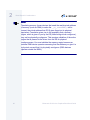
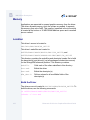
Memory Remapping
Note
For this release of Enhanced OS-9 for StrongARM, only the SA-1100
Brutus reference board uses memory remapping. This section does not
apply to the default ADS board port.
Edition 4.0 of Enhanced OS-9 for ARM supports the translation of
memory from a physical address into a virtual one. This feature makes
the ARM SA1100’s four DRAM banks appear contiguous, which makes
allocating larger amounts of memory possible. This is critical for
applications like JAVA. It also enables custom configuration of the
memory map for your system. The memory translation table for the
system is defined in the following files:
•
$MWOS/OS9000/ARMV4/PORTS/BRUTUS/ROM/ROMCORE/vvectors.a
•
$MWOS/OS9000/ARMV4/PORTS/BRUTUS/ROM/ROMCORE/virt1100.d.
When the system comes up, SSM uses this table's information to
provide the standard OS-9 per process protection. This translation is
possible if the ARM SSM edition #18 or greater is used and the
low-level ROM has been compiled to translate memory—which is the
default setting.
Enhanced OS-9 for the GraphicsClient Board Guide
65
2
Board Specific Considerations
Note
Translating memory forces devices that need the real physical address
of memory (such as DMA) to make the _os_transadd() call to
convert the virtual address that OS-9 gives them into its physical
equivalent. Translation gives rise to the possibility that a memory
region, which is given to you by the OS (while being virtual contiguous),
may not be physically contiguous. This requires validation of the entire
region that is passed to the driver from the OS for physical
contiguousness. You must validate the memory region because an
external DMA device operates assuming that the address you give it is
a physical one and that it is physically contiguous (DMA devices
operate outside the MMU).
66
Enhanced OS-9 for the GraphicsClient Board Guide
2
Board Specific Considerations
Below is example C code demonstrating how a simple, fictitious DMA
driver might use the _os_transadd() call. The ARM SSM will install
the f_transadd system call, which is accessible though the
_oscall() mechanism. The _os_transadd() C binding in
os_lib.l currently contains an old and incompatible version, so a
temporary version _os_transadd_t() is given below.
Sample Code which Utilizes the f_transadd Function
#include
#include
#include
#include
#include
#include
#include
#include
#include
#include
<types.h>
<srvcb.h>
<funcs.h>
<virtual.h>
<sysglob.h>
<svctbl.h>
<srvcb.h>
<funcs.h>
<memory.h>
<errno.h>
/* _os_transadd_t is used instead of _os_transadd because
this function has yet to be integrated into Ultra C. An
older, unused function may be defined which will not work.
You are encouraged to use the _oscall interface or use
transadd_t() function below.
*/
error_code _os_transadd_t(u_int32 *, u_int32, void **, void *);
error_code init(void);
error_code term(void);
#define TO_EXTERNAL (0)
#define TO_LOCAL
(1)
/* local->external bus address */
/* external->local bus address */
#define HARDWARE_DEP0 ((u_int32 *) 0xB0000010)
#define HARDWARE_DEP1 ((u_int32 *) 0xB0000014)
u_int32 DMAbase;
u_int32 VDMAbase;
void *Resv;
/* Physical address */
/* Virtual address */
/* Reserved field
*/
volatile u_int32 *DMAbase_reg1 = HARDWARE_DEP0;
volatile u_int32 *DMAsize_reg1 = HARDWARE_DEP1;
u_int32 size;
/* DMA base reg */
/* Count size */
error_code init()
{
error_code err;
u_int32 dmasize;
size = 0x1000;
/* size of buffer to xfer (4k) */
Enhanced OS-9 for the GraphicsClient Board Guide
67
2
Board Specific Considerations
/* Allocate memory region which will be used by DMA */
if ((err = _os_srqmem(&size, (void **)&VDMAbase, MEM_ANY)) != SUCCESS)
return(err);
dmasize = size;
DMAbase = VDMAbase;
/* Set up to call _os_transadd
/* Set up to call _os_transadd
*/
*/
/* Get physical address for hardware use */
if (!(err = _os_transadd_t(&dmasize, TO_EXTERNAL, (void **)&DMAbase, Resv)))
{
/* No error, check return variables as needed */
if ( size != dmasize) /* Is region covered by one translation. */
{
/* DMA controllers will not work if the memory transfer block
* is not physically contiguous. Some error logic needs to be here
* to parse a possible over-sized request block using loops of the
* _os_transadd call to find a region which is physically contiguous
* _or_ to break up the region into multiple DMA transactions
* (scatter-gather DMA), or to error out (may not be any usable
* contiguous memory). Since the current translations happen only
* on 1 Meg boundaries, it is unlikely that your allocation will not
* be physically contiguous.
*
* One way to guarantee that this passes is to assign a separate
* color node to a region you know to be physically contiguous.
* See the LCD driver example for the BRUTUS board.
*/
_os_srtmem(size, &VDMAbase);
/* return memory */
return(E_IBA);
/* return error for simple case */
}
else /* The whole region is translated setup up simple controller */
{
*DMAbase_reg1 = DMAbase;
/* set base address register */
*DMAsize_reg1 = dmasize;
/* set up size to transfer
*/
/* .
.
.
*/
return(SUCCESS);
/* It’s done, leave */
}
}
/* _os_transadd returned an error (E_IBA or E_UNKSVC) */
else
{
/* In this case memory exists but is not being translated, so
* virtual = physical, and you should use the "virtual" address.
*
* To get here, either SSM has not installed f_transadd, so there
* is NO translating going on, or SSM could not find a matching
* translation for the address you gave it in the translist. In
* either case, the system gave you this memory so it is probably
* good, and NO translation is being done on the region.
*/
68
Enhanced OS-9 for the GraphicsClient Board Guide
2
Board Specific Considerations
*DMAbase_reg1 = VDMAbase;
/* set base address register */
*DMAsize_reg1 = size;
/* set up size to transfer
*/
/* .
.
.
*/
return(SUCCESS);
/* It’s done, leave */
}
}
error_code term()
{
/* To remove the device, remember to use SRTMEM with
* the "virtual" pointer as this is what the OS uses.
* It would probably be best to keep these types of
* pointers in a global area.
*
* If you have the need, you can use _os_transadd(.,TO_LOCAL,.,.)
* to get the virtual address, given a physical address.
*/
}
/* _os_transadd_t - translate an address */
error_code _os_transadd_t(size, mode, blk_addr, reserved)
u_int32
*size;
/* block size to xlate(in), xlate size (out) */
u_int32
mode;
/* direction of translation */
void
**blk_addr; /* addr to xlate (in), xlated addr (out) */
void
*reserved;
/* future use */
{
register error_code
error; /* the error code */
f_transadd_pb
pb;
/* the parameter block */
#if defined(_MPFARM)
*(int*)(&(pb.cb)) = (1 << 16) | F_TRANSADD;
#else
pb.cb.code = F_TRANSADD;
pb.cb.edition = SYSCALL_EDITION;
#endif
pb.cb.param_size = sizeof(f_transadd_pb);
pb.size = *size;
pb.mode = mode;
pb.blk_addr = *blk_addr;
pb.reserved = reserved;
error = _oscall(&pb);
/*
/*
/*
/*
pass
pass
pass
pass
size pointer */
mode */
addresses pointer */
reserved field */
*size = pb.size;
*blk_addr = pb.blk_addr;
return error;
/* return size */
/* return xlated adr */
/* return error */
}
Enhanced OS-9 for the GraphicsClient Board Guide
69
2
Board Specific Considerations
70
Enhanced OS-9 for the GraphicsClient Board Guide
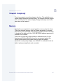
C h a p t e r 3 : O S - 9 RO M I m ag e O v e r v i ew
This chapter is an overview of building an Enhanced OS-9 ROM Image
and its components. Using the Configuration Wizard eliminates the
need to have an in-depth understanding of how to create and update an
OS-9 ROM Image. This chapter explains the types of images created by
the wizard for those interested in more detailed knowledge.
Note
This chapter provides a generic, general overview of the contents of a
typical OS-9 ROM image. It is not board/processor specific.
71
3
OS-9 ROM Image Overview
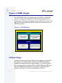
Types of ROM Images
The OS-9 ROM Image is divided into two sets of files to simplify the
process of loading and testing OS-9. The low-level images are the
coreboot files, which boot the target board to an OS-9 boot menu. The
high-level images are the bootfile files, which boot the board up to an
OS-9 shell prompt.
Figure 3-1 OS-9 ROM Image
OS-9 ROM Image
Coreboot
ROMCORE
Low-level System
Modules
Bootfile
kernel
High-level Modules
Coreboot Image
Coreboot is the low-level image that boots the system up to the OS-9
boot menu on the target board. Coreboot is the ROMCore image
merged with several low-level system modules. From this boot menu
you can select a booter module (Flash, PCMCIA ATA card, RAM, etc.).
This tells ROMCore the location from which to load the high-level
system. At this point, OS-9 is not yet capable of running.
72
Enhanced OS-9 for the GraphicsClient Board Guide
3
OS-9 ROM Image Overview
The configuration wizard simplifies the process of building a coreboot
image. Table 3-1 lists the typically included modules. In this case, the
high-level system is to be booted from a PCMCIA card:
Table 3-1 Typical Coreboot Image Contents
Name
Description
bootsys
Booter registration service module.
cnfgdata
Contains the low-level configuration data.
cnfgfunc
Provides access services to cnfgdata data.
commcnfg
Inits communication port defined in cnfgdata.
conscnfg
Inits console port defined in cnfgdata.
console
Provides console services.
dbgentry
Inits debugger entry point for system use.
dbgserve
Provides debugger services.
dbinit
Initilizes any daughter boards present.
excption
Provides low-level exception services.
flshcach
Provides low-level cache management services.
hlproto
Provides user level code access to protoman.
ide
IDE boot support module. PCMCIA compatible.
io1100
Provides polled serial driver support for the low-level
system.
llbootp
Booter that provides bootp services.
Enhanced OS-9 for the GraphicsClient Board Guide
73
3
OS-9 ROM Image Overview
Table 3-1 Typical Coreboot Image Contents (continued)
74
Name
Description
llcis
Inits the PCMCIA interface including cards.
lle509
Provides low-level ethernet services via 3COM
PCMCIA card.
llip
Provides low-level IP services.
llkermit
Booter that uses kermit protocol.
llne2000
Provides low-level ethernet services via
SOCKET-LPE PCMCIA card.
llslip
Provides low-level SLIP services.
lltcp
Provides low-level TCP services.
lludp
Provides low-level UDP services.
notify
Provides state change information for use with LL and
HL drivers.
oemglob
Creates a shared variable area for high/low level
system interactions.
override
Booter that allows choice between menu and auto
booters.
parser
Provides argument parsing services.
pcman
Booter that reads MS-DOS file system.
portmenu
Inits booters defined in the cnfgdata.
protoman
Protocol management module.
Enhanced OS-9 for the GraphicsClient Board Guide
3
OS-9 ROM Image Overview
Table 3-1 Typical Coreboot Image Contents (continued)
Name
Description
restart
Booter that cause a soft reboot of system.
romboot
Booter that allows booting from ROM.
rombreak
Booter that calls the installed debugger.
rombug
Low-level system debugger.
romcore
Board specific initialization code.
sndp
Provides low-level system debug protocol.
splash
Provides way to init LCD screen with a compressed
image.
srecord
Booter that accepts S-Records.
swtimer
Provides timer services via software loops.
tmr1_1100
Provides low-level timer services via time base
register.
usedebug
Inits low-level debug interface to RomBug, SNDP, or
none.
ROMCore
This is the bootstrap code in raw binary object code. ROMCore exists in
the Coreboot image and is responsible for initializing basic hardware,
determining boot options, and determining the RAM/ROM configuration.
ROMCore calls the system level debugger (if available) as well as the
appropriate booter module to find the bootfile. After the high level
system is loaded, ROMCore transfers control over to the kernel.
Enhanced OS-9 for the GraphicsClient Board Guide
75
3
OS-9 ROM Image Overview
Bootfile Image
This image contains the kernel and other high-level modules (init
module, file managers, drivers, descriptors, applications). The image is
loaded based on the device you select from the boot menu. The bootfile
normally brings up a shell prompt, but can be configured to
automatically start your application.
The Configuration Wizard simplifies the process of building a Bootfile
image. Table 3-2 lists the typically included high-level modules.
Table 3-2 Typical Bootfile Image Contents
76
Name
Description
abort
P2module that provides a way to enter the
system-state debugger.
cache
Provides cache control for the CPU cache
hardware. The cache module is in the file cach1100.
fpu
Provides software emulation for floating point
instructions.
gx_sa1100
MFM MAUI driver module with support for an LCD
panel.
init
Descriptor module with high level system
initialization information.
ioman
Provides generic IO support for all IO device types.
irq1100
P2module that provides interrupt acknowledge and
dispatching support for the SA1100 pic.
irq11x1
P2module that provides interrupt acknowledge and
dispatching support for the SA1111 pic (vector
range 0x71-0xB2).
Enhanced OS-9 for the GraphicsClient Board Guide
3
OS-9 ROM Image Overview
Table 3-2 Typical Bootfile Image Contents (continued)
Name
Description
kernel
The kernel provides all basic services for the OS-9
system.
mfm
Provides generic graphics device support for MAUI.
nodisk
Same as init, but used in a disk-less system.
pcf
Provides generic block device management
functions for MS-DOS FAT format.
pipe
Pipeman descriptor that provides a RAM based
FIFO that can be used for process communication.
pipeman
Provides a memory FIFO buffer for communication.
pwrman
P2module that provides generic power
management functions.
pwrplcy
P2module that provides power state control
functions.
r0
RBF descriptor that provides access to a ram disk.
r0.dd
Same as r0 except with module name dd (for use as
the default device).
ram
RBF driver that provides a RAM based virtual block
device.
rb1003
RBF/PCF driver that provides driver support for
IDE/EIDE devices. This driver is used to provide
disk support for PCMCIA ATA FLASH.
Enhanced OS-9 for the GraphicsClient Board Guide
77
3
OS-9 ROM Image Overview
Table 3-2 Typical Bootfile Image Contents (continued)
78
Name
Description
rbf
Provides generic block device management
functions for OS-9 specific format.
rtc1100
Driver that provides OS-9 access to the SA1110
on-board real time clock.
sc1100
SCF driver that provides serial support the
SA1110’s SP1 and SP3 ports when configured as
UARTS.
sc16550
SCF driver that provides serial support for PCMCIA
modem cards.
scf
Provides generic character device management
functions.
scllio
SCF driver that provides serial support via the
polled low-level serial driver.
spe509_pcm
SPF driver to support ethernet for a 3COM
EtherLink III PCMCIA card.
spe91c94
SPF driver to support ethernet for the SMC91C94
chip.
spf
Provides generic protocol device management
function support.
spne2000
SPF driver to support ethernet for a Socket-LPE CF
card.
spucb1200
SPF driver that supports the on-board Phillips
UCB1200 chip. This device communicates to the
SA1100 over SP4 using MCP.
Enhanced OS-9 for the GraphicsClient Board Guide
3
OS-9 ROM Image Overview
Table 3-2 Typical Bootfile Image Contents (continued)
Name
Description
ssm
The System Security Module provides support for
the Memory Management Unit (MMU) on the CPU.
sysif
P2module that provides SA1100 CPU power state
control.
tk1100
Driver that provides the system ticker based on the
SA1110 Operating System Timer.
vectors
Provides interrupt service entry and exit code. The
vectors module is found in the file vect110.
Coreboot and Bootfile Image
The combined coreboot and bootfile images are referred to as the OS-9
ROM Image. The OS-9 ROM Image contains a high-level embedded
OS-9 bootfile as well as the system bootstrap code, low-level system
modules, and embedded utility set for a fully functional OS-9 embedded
system.
Enhanced OS-9 for the GraphicsClient Board Guide
79
3
OS-9 ROM Image Overview
Boot Menu Options
You select your boot device menu options using the configuration
wizard. For each boot device option, you can select whether you want it
to be displayed on a boot menu, set up to autoboot, or both. The
autoboot option enables the device selected to automatically boot up
the high-level bootfile, bypassing the boot device menu.
Note
When using the Configuration Wizard, you should select only one
device for autoboot on your system.
Following is an example of the Boot Menu displayed in the terminal
emulation window (using Hyperterminal):
OS-9000 Bootstrap for the ARM
ATA IDE disk found in socket 00
Now trying to Override autobooters.
BOOTING PROCEDURES AVAILABLE ------------- <INPUT>
Boot embedded OS-9000 in-place ----------Copy embedded OS-9000 to RAM and boot ---Boot from PCMCIA-1 IDE ------------------Boot from PCMCIA-0 IDE ------------------Load bootfile via kermit Download -------Download and Program coreboot into FLASH Download and Program bootfile into FLASH Restart the System ----------------------Enter system debugger --------------------
<N/A>
<N/A>
<ide1>
<ide0>
<ker>
<dbc>
<dbb>
<q>
<break>
Select a boot method from the above menu: ide0
80
Enhanced OS-9 for the GraphicsClient Board Guide
3
OS-9 ROM Image Overview
What you select for boot options in the configuration wizard determines
what modules are included in the coreboot image. Table 3-3 lists some
of the supported boot devices for Enhanced OS-9:
Table 3-3 Supported Boot Methods
Type of Boot
Description
PCMCIA ATA Card
Copy OS-9 from ATA hard drive to
RAM and boot (ide0).
Boot embedded OS-9
in-place
Boot OS-9 from FLASH (bo)
Copy embedded OS-9 to
RAM and Boot
Copy OS-9 from FLASH (if stored
there) to RAM and boot (lr).
Enhanced OS-9 for the GraphicsClient Board Guide
81
3
OS-9 ROM Image Overview
Debuggers
The configuration wizard supports two debuggers, Microware Hawk™
and ROMBug. It installs the appropriate low-level modules in your
coreboot file when you make your build. The selection is then contained
in the coreboot image that is downloaded to your target system.
Microware Hawk™
Microware Hawk™ and its debugger enable you to create, run, debug,
and update your programs. It is included on your Enhanced OS-9 CD.
RomBug
RomBug is used to debug system and user state programs. It runs in
supervisor state and takes over control of the CPU when invoked.
RomBug is configured as a low-level module that gains access to the
resources it needs by using other low-level modules.
82
Enhanced OS-9 for the GraphicsClient Board Guide
3
OS-9 ROM Image Overview
Including Options in Your Build
Using the configuration wizard, there are additional options you can
select as part of your build. These options enable increased
functionality on the target system. Following are descriptions of some of
these options.
ROM Utility Set
Table 3-4 lists the utilities in the ROM utility set.
Table 3-4 ROM Utility Set
More In
fo More
Informatio
n More Inf
ormation M
ore Inform
ation More
-6-
shell
date
devs
break
deiniz
dump
echo
events
exbin
help
ident
iniz
irqs
link
maps
mdir
mfree
printenv
procs
setime
sleep
tmode
unlink
xmode
For More Information
For more information on ROM utilities, see the OS-9 Utilities
Reference.
Enhanced OS-9 for the GraphicsClient Board Guide
83
3
OS-9 ROM Image Overview
RomBug in Bootfile (p2init)
The p2init utility initializes an OS9P2 system extension module after
the operating system is up and running. This provides additional
functionality which would not be available when the OS9P2 module is
initialized as part of the system startup. You can also use the p2init
utility to add OS9P2 modules to a running ROM-based system.
User State Debugging Modules
User state is the normal program environment in which processes are
executed. Generally, user-state processes do not deal directly with the
specific hardware configuration of the system. System-state debugging
is defined as debugging the entire system as opposed to just one
process running on the system (user-state debugging). System-state
debugging is initiated by using the attach command either to attach to a
system or to an emulator.
Enable Disk Support Modules
These modules support disk and tape devices in addition to utilities to
manipulate these device classes. It adds RBF, PCF, and SCF based I/O
devices.
Disk Utilities
These utilities provide utilities for partitioning, formatting, and
maintaining disks on target systems.
SoftStax Support Modules
These modules support the SoftStax communications environment on
target systems.
84
Enhanced OS-9 for the GraphicsClient Board Guide
3
OS-9 ROM Image Overview
NFS Client Support Module
This module provides support for the Network File System (NFS).
Keyboard Support
This enables the use of a keyboard attached to the target system.
Mouse Support
This enables the use of a mouse as an input device on the target
system.
User Modules
By default, the only module included is kermit. You can include other
modules by editing the user.ml file under the Sources-Port pull-down
menu found in the configuration wizard Advanced Mode.
Enhanced OS-9 for the GraphicsClient Board Guide
85
3
OS-9 ROM Image Overview
86
Enhanced OS-9 for the GraphicsClient Board Guide
Ap p e n d i x A : T h e Fa s t b o o t
E n h a n c e me nt
The Fastboot enhancements to OS-9 provide faster system bootstrap
performance to embedded systems. The normal bootstrap performance
of OS-9 is attributable to its flexibility. OS-9 handles many different
runtime configurations to which it dynamically adjusts during the
bootstrap process.
The Fastboot concept consists of informing OS-9 that the defined
configuration is static and valid. These assumptions eliminate the
dynamic searching OS-9 normally performs during the bootstrap
process and enables the system to perform a minimal amount of
runtime configuration. As a result, a significant increase in bootstrap
speed is achieved.
87
A
The Fastboot Enhancement
Overview
The Fastboot enhancement consists of a set of flags that control the
bootstrap process. Each flag informs some portion of the bootstrap
code that a particular assumption can be made and that the associated
bootstrap functionality should be omitted.
The Fastboot enhancement enables control flags to be statically defined
when the embedded system is initially configured as well as
dynamically altered during the bootstrap process itself. For example, the
bootstrap code could be configured to query dip switch settings,
respond to device interrupts, or respond to the presence of specific
resources which would indicate different bootstrap requirements.
In addition, the Fastboot enhancement’s versatility allows for special
considerations under certain circumstances. This versatility is useful in
a system where all resources are known, static, and functional, but
additional validation is required during bootstrap for a particular
instance such as a resource failure. The low-level bootstrap code could
respond to some form of user input that would inform it that additional
checking and system verification is desired.
88
Enhanced OS-9 for the GraphicsClient Board Guide
A
The Fastboot Enhancement
Implementation Overview
The Fastboot configuration flags have been implemented as a set of bit
fields. An entire 32-bit field has been dedicated for bootstrap
configuration. This four-byte field is contained within the set of data
structures shared by the ModRom sub-components and the kernel.
Hence, the field is available for modification and inspection by the entire
set of system modules (high-level and low-level). Currently, there are
just six bit flags defined with eight bits reserved for user-definable
bootstrap functionality. The reserved user-definable bits are the
high-order eight bits (31-24). This leaves bits available for future
enhancements. The currently defined bits and their associated
bootstrap functionality are listed below:
B_QUICKVAL
The B_QUICKVAL bit indicates that only the module headers of
modules in ROM are to be validated during the memory module search
phase. This causes the CRC check on modules to be omitted. This
option is potentially a large time saver due to the complexity and
expense of CRC generation. If a system has many modules in ROM,
where access time is typically longer than RAM, omitting the CRC
check on the modules will drastically decrease the bootstrap time. It is
fairly rare that corruption of data occurs in ROM. Therefore, omitting
CRC checking will usually be a safe option.
B_OKRAM
The B_OKRAM bit informs both the low-level and high-level systems that
they should accept their respective RAM definitions without verification.
Normally, the system probes memory during bootstrap based on the
defined RAM parameters. This allows system designers to specify a
possible RAM range which the system will validate upon startup. Thus
the system can accommodate varying amounts of RAM. But in an
embedded system where the RAM limits are usually statically defined
Enhanced OS-9 for the GraphicsClient Board Guide
89
A
The Fastboot Enhancement
and presumed to be functional, there is no need to validate the defined
RAM list. Bootstrap time is saved by assuming that the RAM definition is
accurate.
B_OKROM
The B_OKROM bit causes acceptance of the ROM definition without
probing for ROM. This configuration option behaves just like the
B_OKRAM option except that it applies to the acceptance of the ROM
definition.
B_1STINIT
The B_1STINIT bit causes acceptance of the first init module found
during cold-start. By default, the kernel searches the entire ROM list
passed up by the ModRom for init modules before it accepts and uses
the init module with the highest revision number. In a statically
defined system, time is saved by using this option to omit the extended
init module search.
B_NOIRQMASK
The B_NOIRQMASK bit informs the entire bootstrap system that it should
not mask interrupts for the duration of the bootstrap process. Normally,
the ModRom code and the kernel cold-start mask interrupts for the
duration of the system startup. But some systems that have a well
defined interrupt system (i.e. completely calmed by the sysinit
hardware initialization code) and also have a requirement to respond to
an installed interrupt handler during system startup can enable this
option to prevent the ModRom and the kernel cold-start from disabling
interrupts. This is particularly useful in power-sensitive systems that
need to respond to “power-failure” oriented interrupts.
90
Enhanced OS-9 for the GraphicsClient Board Guide
A
The Fastboot Enhancement
Note
Some portions of the system may still mask interrupts for short periods during the
execution of critical sections.
B_NOPARITY
If the RAM probing operation has not been omitted, the B_NOPARITY
bit causes the system to not perform parity initialization of the RAM.
Parity initialization occurs during the RAM probe phase. The
B_NOPARITY option is useful for systems that either require no parity
initialization at all or systems that only require it for “power-on” reset
conditions. Systems that only require parity initialization for initial
“power-on” reset conditions can dynamically use this option to prevent
parity initialization for subsequent “non-power-on” reset conditions.
Enhanced OS-9 for the GraphicsClient Board Guide
91
A
The Fastboot Enhancement
Implementation Details
This section describes the compile-time and runtime methods by which
users can control the bootstrap speed of their system.
Compile-time Configuration
The compile-time configuration of the bootstrap is provided by a
pre-defined macro (BOOT_CONFIG) which is used to set the initial
bit-field values of the bootstrap flags. Users can redefine the macro for
recompilation to create a new bootstrap configuration. The new
over-riding value of the macro should be established by redefining the
macro in the rom_config.h header file or as a macro definition
parameter in the compilation command.
The rom_config.h header file is one of the main files used to
configure the ModRom system. It contains many of the specific
configuration details of the low-level system. Here is an example of
how a user can redefine the bootstrap configuration of their system
using the BOOT_CONFIG macro in the rom_config.h header file:
#define BOOT_CONFIG (B_OKRAM + B_OKROM + B_QUICKVAL)
And here is an alternate example showing the default definition as a
compile switch in the compilation command in the makefile:
SPEC_COPTS = -dNEWINFO –dNOPARITYINIT –dBOOT_CONFIG=0x7
This redefinition of the BOOT_CONFIG macro would result in a bootstrap
method which would accept the RAM and ROM definitions as they are
without verification, and also validate modules solely on the correctness
of their module headers.
Runtime Configuration
The default bootstrap configuration can be overridden at runtime by
changing the rinf->os->boot_config variable from either a
low-level P2 module or from the sysinit2() function of the
92
Enhanced OS-9 for the GraphicsClient Board Guide
A
The Fastboot Enhancement
sysinit.c file. The runtime code can query jumper or other hardware
settings to determine what user-defined bootstrap procedure should be
used. An example P2 module is shown below.
Note
If the override is performed in the sysinit2() function, the effect is
not realized until after the low-level system memory searches have
been performed. This means that any runtime override of the default
settings pertaining to the memory search must be done from the code
in the P2 module code.
#define NEWINFO
#include <rom.h>
#include <types.h>
#include <const.h>
#include <errno.h>
#include <romerrno.h>
#include <p2lib.h>
error_code p2start(Rominfo rinf, u_char *glbls)
{
/* if switch or jumper setting is set… */
if (switch_or_jumper == SET) {
/* force checking of ROM and RAM lists */
rinf->os->boot_config &= ~(B_OKROM+B_OKRAM);
}
return SUCCESS;
}
Enhanced OS-9 for the GraphicsClient Board Guide
93
A
The Fastboot Enhancement
94
Enhanced OS-9 for the GraphicsClient Board Guide
A p p e n d i x B : M AU I D r i v e r D e s c r i p t i o n s
This chapter provides MAUI driver descriptions. It includes the following
sections:
•
GraphicsClient Objects
•
GX_SA1100 LCD Graphic Driver Specification
•
GX_SA1101 VGA Graphic Driver Specification
•
SD_UCB1200 Sound Driver Specification
•
SPUCB1200 driver for the UCB1200 Codec
•
MP_UCB1200 MAUI Touch screen Protocol Module
95
B
MAUI Driver Descriptions
GraphicsClient Objects
This package provides object-level support for the Intel GraphicsClient
reference board. The port directory is at the following location:
MWOS/OS9000/ARMV4/PORTS/GRAPHICSCLIENT
MAUI objects
96
cdb
Lists the devices on the system.
mp_msptr
Serial mouse protocol module.
mp_ucb1200
Touch screen protocol module for the
UCB1200.
gfx and gx_sa1100
LCD graphics descriptor and driver.
Enhanced OS-9 for the GraphicsClient Board Guide
B
MAUI Driver Descriptions
GX_SA1100 LCD Graphic Driver Specification
This section describes the hardware specification of the StrongARM
SA1100 LCD driver (named gx_sa1100) and descriptor (named gfx).
The hardware sub-type defines the board configuration. This
specification should be used with the MAUI Graphics Device API.
Board Ports
This driver is used in two of the three example board StrongArm ports.
The Brutus board uses a Kyocera KCS057QV1AA-G03 (formerly
KCS3224ASTT-X1), 8 bpp Color, STN, with a resolution of 320x480
single panel.
The GraphicsClient board uses a Sharp LQ64D341 18 bpp color (16
used), TFT, with a resolution of 640x480 single panel. This panel is
connected to the GraphicsClient with one of several possible cables:
•
8 bpp - most common to date
•
RGB 565 - next most common
•
RGB 655
•
RGB 556
The SideArm board can support an LCD panel, but does not typically
ship with one. For this reason the SideArm port does not build this
driver. If the user did connect a LCD panel to this board, simply copy the
makefiles from one of the other ports into the SideArm port.
Enhanced OS-9 for the GraphicsClient Board Guide
97
B
MAUI Driver Descriptions
Device Capabilities
Information about the hardware capabilities is determined by calling
gfx_get_dev_cap(). The hardware sub-type defines the board
configuration. This function returns a data structure formatted as shown
in Table B-1. See GFX_DEV_CAP for more information about this data
structure.
Table B-1 gfx_get_dev_cap() Data Structure
98
Member Name
Description
Value
hw_type
Hardware type
(embedded in driver)
SA1100 LCD Controller
hw_subtype
Hardware subtype
(embedded in
descriptor)
Brutus 8 bit color LCD,
Graphicsclient 8 bit color
LCD, or GraphicsClient
16 bit color LCD
sup_vpmix
Supports viewport
mixing
FALSE
sup_extvid
Supports external
video as a backup
FALSE
sup_bkcol
Supports background
color
FALSE
sup_vptrans
Supports viewport
transparency
FALSE
sup_vpinten
Supports viewport
intensity
FALSE
sup_sync
Supports retrace
synchronization
FALSE
Enhanced OS-9 for the GraphicsClient Board Guide
B
MAUI Driver Descriptions
Table B-1 gfx_get_dev_cap() Data Structure (continued)
Member Name
Description
Value
num_res
Number of display
resolutions
1
res_info
Array of display
resolution
information
See Display Resolution
table
dac_depth
Depth of the DAC in
bits
12
num_cm
Number of coding
methods
1
cm_info
Array of coding
method information
See Coding Methods
table
sup_viddecode
Supports video
decoding into a
drawmap
FALSE
Display Resolution
The display resolution is configured by the descriptor and can be
changed to support LCD panels of different sizes. The driver is only
designed to support one resolution at a time. That resolution is
Enhanced OS-9 for the GraphicsClient Board Guide
99
B
MAUI Driver Descriptions
specified by the descriptor. Modify the DEFAULT_RES macro in
mfm_desc.h to change the resolution. If you change the resolution,
you must also change all of the LCD timing fields as well.
Table B-2 Display Specifications
Board
Width
Height
Refresh
Rate
Interlace Mode
Aspect
Ratio
X:Y
Brutus
320
240
0*
GFX_INTL_OFF
1:1
GraphicsClient
640
480
0*
GFX_INTL_OFF
1:1
*Refresh rate is determined by timing specified in descriptor. The
devcap is not automatically update to reflect this.
Coding Methods
The coding method is also configured by the descriptor and can be
changed to support b/w and color LCD panels. The coding method can
be selected in the descriptor by simply specifying the coding method in
the DEFAULT_CM macro in mfm_desc.h.
100
Enhanced OS-9 for the GraphicsClient Board Guide
B
MAUI Driver Descriptions
This driver was verified on the Brutus evaluation board with an 8-bit
cable, and a GraphicsClient with both a 8-bit and 565 cables. The
maximal coding method supported by SA1100 LCD Controller is 16
bpp.
Table B-3 Coding Method Description
Coding
Method
CLUT
Based
X,Y
Multipliers
Palette Color Types
Brutus, and
GraphicsClient w/8 bit
cable
GFX_CM_8BIT
TRUE
1,1
GFX_COLOR_RGB
GraphicsClient w/16
bit cable
GFX_CM_565,
GFX_CM_655,
or
GFX_CM_556
FALSE
1,1
NA
No current
hardware
implementati
on available
GFX_CM_4BIT
TRUE
1,1
GFX_COLOR_RGB
Board
Viewport Complexity
The driver supports one active viewport at a time. The application can
create multiple viewports and stack them. The viewport must be aligned
with, and the same size as the display. Display drawmaps must be the
same size as the viewport.
Enhanced OS-9 for the GraphicsClient Board Guide
101
B
MAUI Driver Descriptions
Memory
Applications are expected to request graphics memory from the driver.
The driver allocates memory from the system as needed. It requests
this memory from color 0x80. This memory (specified in the init module)
is located at the bottom of 16 MB DRAM address space and is marked
as non cached.
Location
This driver’s source is located in:
SRC/DPIO/MFM/DRVR/GX_SA1100
This driver’s makefiles are located in:
OS9000/ARMV4/PORTS/BRUTUS/MAUI/GX_SA1100, and
OS9000/ARMV4/PORTS/GRAPHICSCLIENT/MAUI/GX_SA1100
This directory contains the makefiles and descriptor header file to build
the descriptor(s) and driver(s) (not all packages include driver source)
for the StrongARM reference platform. This directory contains:
makefile
Calls each of the other makefiles in this directory
drvr.mak
Builds the driver
desc.mak
Builds the descriptor(s)
mfm_desc.h
Defines values for all modifiable fields of the
descriptor(s)
Build the Driver
The driver source is located in SRC/DPIO/MFM/DRVR/GX_SA1100. To
build the driver, use the following commands:
cd OS9000/ARMV4/PORTS/BRUTUS/MAUI/GX_SA1100
os9make -f drvr.mak
102
Enhanced OS-9 for the GraphicsClient Board Guide
B
MAUI Driver Descriptions
Build the Descriptor
To build a new descriptor, modify mfm_desc.h, and use the following
commands to compile:
cd OS9000/ARMV4/PORTS/BRUTUS/MAUI/GX_SA1100, or
OS9000/ARMV4/PORTS/GRAPHICSCLIENT/MAUI/GX_SA1100
os9make -f desc.mak
To build both the driver and the descriptor you can specify os9make
with no parameters.
Enhanced OS-9 for the GraphicsClient Board Guide
103
B
MAUI Driver Descriptions
GX_SA1101 VGA Graphic Driver Specification
This section describes the hardware specification of the
StrongARM/SideKick SA1101 VGA driver (gx_sa1101) and descriptor
(vga). The hardware sub-type defines the board configuration. This
specification should be used with the MAUI Graphics Device API.
Device Capabilities
Information about the hardware capabilities is determined by calling
gfx_get_dev_cap(). The hardware sub-type defines the board
configuration. This function returns a data structure formatted as shown
in Table B-4. See GFX_DEV_CAP for more information about this data
structure.
Table B-4 gfx_get_dev_cap() Data Structure
104
Member Name
Description
Value
hw_type
Hardware type (embedded in
driver)
SA1101 VGA
Controller
hw_subtype
Hardware subtype (embedded
in descriptor)
Sidekick VGA
Controller w/
IOBLT
sup_vpmix
Supports viewport mixing
FALSE
sup_extvid
Supports external video as a
backup
FALSE
sup_bkcol
Supports background color
TRUE
sup_vptrans
Supports viewport
transparency
FALSE
Enhanced OS-9 for the GraphicsClient Board Guide
B
MAUI Driver Descriptions
Table B-4 gfx_get_dev_cap() Data Structure (continued)
Member Name
Description
Value
sup_vpinten
Supports viewport intensity
FALSE
sup_sync
Supports retrace
synchronization
TRUE
num_res
Number of display resolutions
3
res_info
Array of display resolution
information
See Display
Resolution
table
dac_depth
Depth of the DAC in bits
12
num_cm
Number of coding methods
1
cm_info
Array of coding method
information
See Coding
Methods table
sup_viddecode
Supports video decoding into a
drawmap
FALSE
Display Resolution
The display resolution is configured by the descriptor and can be
changed to support LCD panels of different sizes. The driver is only
designed to support one resolution at a time. That resolution is
Enhanced OS-9 for the GraphicsClient Board Guide
105
B
MAUI Driver Descriptions
specified by the descriptor. Modify the DEFAULT_RES macro in
mfm_desc.h to change the resolution. If you change the resolution,
you must also change all of the LCD timing fields as well.
Table B-5 Display Specifications
Width
Height
Refresh
Rate
640
480
72.8
GFX_INTL_OFF
1:1
800*
600
72.8
GFX_INTL_OFF
1:1
1024*
768
70.4
GFX_INTL_OFF
1:1
Interlace Mode
Aspect Ratio X:Y
*Dedicated memory mode only
Coding Methods
The coding method is also configured by the descriptor and can be
changed to support b/w and color LCD panels. The coding method can
be selected in the descriptor by simply specifying the coding method in
the DEFAULT_CM macro in mfm_desc.h.
This driver was verified on the Brutus evaluation board with an 8-bit
cable, and a GraphicsClient with both a 8-bit and 565 cables. The
maximal coding method supported by SA1100 LCD Controller is 16
bpp.
Table B-6 Coding Method Description
106
Coding Method
CLUT
Based
X,Y
Multipliers
Palette Color Types
GFX_CM_8BIT
TRUE
1,1
GFX_COLOR_RGB
Enhanced OS-9 for the GraphicsClient Board Guide
B
MAUI Driver Descriptions
Viewport Complexity
The driver supports one active viewport at a time. The application can
create multiple viewports and stack them. The viewport must be aligned
with, and the same size as the display. Display drawmaps must be the
same size as the viewport.
Memory
Applications are expected to request graphics memory from the driver.
The driver allocates memory from the system as needed. It requests
this memory from color 0x80. This memory (specified in the init module)
is located at the high end of the 16/32 MB DRAM address space and is
marked as non cached.
The driver can operate in either unified or dedicated mode. On the
development SideArm/SideKick board we recommend against the
unified mode because the system does not have the memory
bandwidth to adequately display even 640x480. In dedicated mode we
had to implement significant work arounds to
Enhanced OS-9 for the GraphicsClient Board Guide
107
B
MAUI Driver Descriptions
Location
This driver’s source is located in:
SRC/DPIO/MFM/DRVR/GX_SA1101
This driver’s makefiles are located in:
OS9000/ARMV4/PORTS/SIDEARM/MAUI/GX_SA1101
This directory contains the makefiles and descriptor header file to build
the descriptor(s) and driver(s) (not all packages include driver source)
for the StrongARM reference platform. This directory contains:
makefile
Calls each of the other makefiles in this directory
drvr.mak
Builds the driver
desc.mak
Builds the descriptor(s)
mfm_desc.h
Defines values for all modifiable fields of the
descriptor(s)
Build the Driver
The driver source is located in SRC/DPIO/MFM/DRVR/GX_SA1101. To
build the driver, use the following commands:
cd OS9000/ARMV4/PORTS/SIDEARM/MAUI/GX_SA1101
os9make -f drvr.mak
Build the Descriptor
To build a new descriptor, modify mfm_desc.h, and use the following
commands to compile:
cd OS9000/ARMV4/PORTS/SIDEARM/MAUI/GX_SA1101
os9make -f desc.mak
To build both the driver and the descriptor you can specify os9make
with no parameters.
108
Enhanced OS-9 for the GraphicsClient Board Guide
B
MAUI Driver Descriptions
SD_UCB1200 Sound Driver Specification
This section describes the hardware specifications for the Philips
UCB1200 driver sd_ucb1200. The hardware sub-type defines the
board configuration. This specification should be used in conjunction
with the MAUI Sound Driver Interface.
This driver works in conjunction with the spucb1200 driver.
Device Capabilities
Information about the hardware capabilities is determined by calling
_os_gs_snd_devcap(). This function returns a data structure
formatted as in the following table. See SND_DEV_CAP for more
information about this data structure.
Table B-7 Data Returned in SND_DEV_CAP
Member Name
Value
Description
hw_type
CS4231
Hardware type
hw_subtype
CS4231A
Hardware sub-type
sup_triggers
SND_TRIG_ANY
Supported triggers
play_lines
SND_LINE_SPEAKER
Play gain/mix lines
record_lines
SND_LINE_MIC
Record gain/mix
lines
sup_gain_cmds
SND_GAIN_CMD_MONO
Mask of supported
gain commands
num_gain_caps
2
Number of
SND_GAIN_CAPs
Enhanced OS-9 for the GraphicsClient Board Guide
109
B
MAUI Driver Descriptions
Table B-7 Data Returned in SND_DEV_CAP (continued)
110
Member Name
Value
Description
gain_caps
See Gain Capabilities
Array
Pointer to
SND_GAIN_CAP
array
num_rates
30
Number of sample
rates
sample_rates
See Sample Rates
Pointer to sample
rate array
num_chan_info
1
Number of channel
info entries
channel_info
See Number of Channels
Pointer to channel
info array
num_cm
3
Number of coding
methods
cm_info
See Encoding and
Decoding Formats
Pointer to coding
method array
Enhanced OS-9 for the GraphicsClient Board Guide
B
MAUI Driver Descriptions
Gain Capabilities Array
The following tables show the various gain capabilities for the Philips
UCB1200. This information is pointed to by the gain_cap member of the
SND_DEV_CAP data structure. See SND_GAIN_CAP for more
information about this data structure. This driver allows control of
following individual physical gain controls:
Table B-8 Individual Gain Controls
SND LINE SPEAKER
Output Attenuation
SND LINE MIC
Microphone Gain
The following tables detail the various individual gain capabilities:
Table B-9 Speaker Gain Enable
Member Name
Value
Step
HW
Level
Comments
lines
SND_LINE_SPEAKER
0-3
31
-69 dB
default_level
sup_mute
TRUE
4-7
30
-66.8 dB
default_type
SND_GAIN_CMD_MONO
8-11
29
-64.7 dB
default_level
SND_LEVEL_MAX
12-15
28
-62.5 dB
zero_level
SND_LEVEL_MIN
...
...
...
num_steps
32
112-115
3
-6.5 dB
step_size
216
116-119
2
-4.3 dB
mindb
-6900
120-123
1
-2.2 dB
maxdb
0
124-127
0
0.0 dB
Enhanced OS-9 for the GraphicsClient Board Guide
zero_level
111
B
MAUI Driver Descriptions
Table B-10 Mic Gain Enable
112
Member Name
Value
Step
HW
Level
Comments
lines
SND_LINE_MIC
0-3
0
0 dB
zero_level
sup_mute
FALSE
4-7
1
0.7 dB
default_type
SND_GAIN_CMD_MONO
...
...
...
...
default_level
SND_LEVEL_MAX
64-67
16
11.3 dB
default_level
zero_level
SND_LEVEL_MIN
...
...
...
...
num_steps
32
112-115
step_size
70
116-119
29
21.1 dB
mindb
0
120-123
30
21.8 dB
maxdb
2250
124-127
31
22.5 dB
20.4 dB
Enhanced OS-9 for the GraphicsClient Board Guide
B
MAUI Driver Descriptions
Sample Rates
Following is an abbreviated list of the supported sample rates for the
UCB1200. Below is a formula to derive valid sample rates:
sample_rate = 11981000/(32 * i), where 8 < i < 128
This information is pointed to by the sample_rates member of the
SND_DEV_CAP data structure.
Table B-11 Sample Rate (Hz)
2948
3941
4926
5942
6933
7966
8914
9852
10697
11700
12910
13866
14976
15600
17828
18720
19705
20800
22023
23400
24960
26743
28800
31200
34036
37440
41600
46801
53486
62401
Number of Channels
The following table shows the different supported number of channels
for the Philips UCB1200. The first entry in the table is the default
number of channels. This information is pointed to by the
channel_info member of the SND_DEV_CAP data structure.
Table B-12 Number of Channels
Channels
Description
1
Mono
Enhanced OS-9 for the GraphicsClient Board Guide
113
B
MAUI Driver Descriptions
Encoding and Decoding Formats
The following table shows the supported encoding and decoding
formats for the Philips UCB1200. The first entry in the table is the
default format. This information is pointed to by the cm_info member
of the SND_DEV_CAP data structure.
Table B-13 Encoding and Decoding Formats
114
Coding Method
Sample
Size
Boundary
Size
SND_CM_PCM_ULAW
8
2
8 bit u-Law
commanded
SND_CM_PCM_SLINEAR 16
SND_CM_LSBYTE1ST
4
16 bit Linear (two’s
complement) little
endian
SND_CM_PCM_SLINEAR 16
4
16 bit Linear signed
(two’s complement)
big endian
Description
Enhanced OS-9 for the GraphicsClient Board Guide
B
MAUI Driver Descriptions
SPUCB1200 driver for the UCB1200 Codec
This document describes the hardware specifications for the Philips
UCB1200 driver. This is an SPF driver.
Capabilities
The UCB1200 is capable of controlling a microphone/speaker,
input/output telecommunications lines, resistive style touch screen, and
16 General Purpose Input/Output lines. This driver currently can only
control the touch screen, and general purpose input/output lines. The
microphone/speaker can be controlled with a MAUI Sound driver called
sd_ucb1200. No driver has been written for the telecommunications
part of the UCB1200.
Descriptors
Table B-14 lists the UCB1200 descriptors.
Table B-14
Name
Function
ucb
UCB1200 Chip Initialization
ucb_audio
Not Implemented
ucb_touch
Touch Screen
ucb_gpio
Control GPIO Lines
ucb_telecom
Not Implemented
Enhanced OS-9 for the GraphicsClient Board Guide
115
B
MAUI Driver Descriptions
UCB
Opening the /ucb device will perform basic chip initialization. Normally
this is not necessary, unless another driver is written to control part of
the UCB1200 functions. This is the case for audio. The MAUI Sound
driver sd_ucb1200 will open /ucb to perform chip initialization. In this
way, the MAUI Sound driver play audio and this driver can control the
touch screen at the same time.
Audio
This portion of the driver is not implemented since the MAUI Sound
driver sd_ucb1200 already exists. sd_ucb1200 and this driver can
co-exist.
Touch Screen
This portion of the driver controls the touch screen operation. When
pressure is applied to the touch screen, a hardware interrupt is raised,
and this driver’s interrupt service routine will execute. A system state
alarm, then, will fire at regular intervals to sample data from the touch
screen. When pressure is removed, the alarm stops. This mechanism
leaves the UCB1200 in a low power state until the user presses the
touch screen. The alarm rate can be controlled in the ucb_touch
descriptor.
116
Enhanced OS-9 for the GraphicsClient Board Guide
B
MAUI Driver Descriptions
Each sample contains an x, y coordinate as well as pressure
information. The data is formatted into a six byte packet as defined in
the table below. Each packet contains 10 bits of x, 10 bits of y, and 8 bits
of pressure information.
Table B-15 Touch Screen Descriptor Data
Byte number
Description
0
sync code - 0x80
1
header:
bit 1: pendown
bit 2: penup
bit 3: penmove (may occur with pendown or penup)
2
bits 0..2: high 3 bits of x
bits 3..6: high 4 bits of pressure
bit 7: 0
3
bits 0..6: low 7 bits of x
bit 7: 0
4
bits 0..2: high 3 bits of y
bits 3..6: low 4 bits of pressure
5
bits 0..6: low bits of y
bit 7: 0
GPIO
This section of the driver has basic GPIO line control, where lines 0..9
are connected to a 7 segment display or LED. Each line can be
controlled with an _os_write() call. (Refer to the UCBHEX program
in the TEST directory.)
Enhanced OS-9 for the GraphicsClient Board Guide
117
B
MAUI Driver Descriptions
Telecom
This portion of the driver is not implemented.
Supporting Modules
Before this driver can be used, the following modules must be in
memory: spf, sysmbuf, mbinstall. mbinstall must also be run
before use.
118
Enhanced OS-9 for the GraphicsClient Board Guide
B
MAUI Driver Descriptions
MP_UCB1200 MAUI Touch screen Protocol
Module
This document describes the function of the mp_ucb1200 protocol
module, as well as a high level discussion of the touch screen driver
and calibration application.
Overview
The protocol module converts the driver raw data into a MAUI_MSG
structure. In this way, applications can remain somewhat ignorant of the
details of the hardware since it deals with the MAUI Input layer. In this
protocol module, the raw hardware data is converted into screen
coordinates. In addition, some data filtering occurs to reduce the
amount of erroneous data that the touch screen hardware can produce.
Data Format
The touch screen driver sends a 6 byte packet that contains x, y, and
pressure information. The exact format of this packet is described in the
spucb1200 driver.
Data Filter
This protocol module filters the data coming from the hardware in an
attempt to reduce erroneous data. Two methods are implemented: data
point averaging and low pressure point removal. The first method will
average the last two points received from the driver. The data point will
lag slightly behind the current position, then, but the average will reduce
erroneous data points produced by the hardware. The second method
throw out data points where the pressure below a certain threshold. It
seems that extremely light touches will cause the data to become
erratic, although the exact pressure threshold is hardware dependent.
Enhanced OS-9 for the GraphicsClient Board Guide
119
B
MAUI Driver Descriptions
Raw Mode
An application can put this protocol module in a "raw" mode where data
points are not filtered, averaged, or converted to screen coordinates.
That is, the data from the hardware is passed directly up to the
application.
The application can put this protocol module in a "raw" mode by calling:
inp_set_sim_meth(inpdev,RAW_MODE). After calibration, the
program will need to put the protocol module back in NATIVE mode by
calling: inp_set_sim_meth(inpdev,DEFAULT_SIM_METH). There
is a sample touch screen Calibration Application in the TOUCH_CAL
directory.
When the protocol module is taken out of "raw" mode, it will try to read
new calibration data points from the ucb1200.dat data module. After the
data is read from the module, it is no longer needed.
cdb.touch
The touch screen can be registered with MAUI by loading the
cdb.touch module in memory before any programs using input are
started. This will specify the spucb1200 as the driver, cdb.touch as
the descriptor, and mp_ucb1200 as the protocol module.
120
Enhanced OS-9 for the GraphicsClient Board Guide
B
MAUI Driver Descriptions
Compile Time Options
Table B-16 shows compile time options used to control the default
calibration settings and also the screen size. These options can be
specified with a value in the mp_ucb1200 makefile to modify the
defaults.
Table B-16 Compile Time Options
Name
Purpose
SCREEN_WIDTH
Screen Width in Pixels
SCREEN_HEIGHT
Screen Weight in Pixels
DEFAULT_CALIBRATION_X
Left Calibration Hardware Point
DEFAULT_CALIBRATION_Y
Top Calibration Hardware Point
DEFAULT_CALIBRATION_WIDTH
Width of Screen In Hardware Points
DEFAULT_CALIBRATION_HEIGHT
Height of Screen In Hardware Points
JITTER_THRESHOLD
Minimum Pixel Change Required Before Points are
Reported to the Application.
NUM_PTS
This allows you to choose how many successive data
points to average in order to produce less erroneous
screen coordinate data to the application. The default is
2, and valid choices are 1, 2, 4, 8, 16.
MIN_PRESSURE
Any pressure point less than this value will be ignored.
This is another way to reduce erroneous data. This
represents the 8 bit pressure value we get from the
driver. The default is 40.
Enhanced OS-9 for the GraphicsClient Board Guide
121
B
MAUI Driver Descriptions
Calibration Application
There is a sample calibration application located in the
$(MWOS)/SRC/MAUI/MP/MP_UCB1200/TOUCH_CAL directory. This
application, called touch_cal, will present a text message on the
screen as well as points for the user to press. After the points are
pressed, the protocol module mp_ucb1200 will be updated with the
new calibration information.
Assumptions/Dependencies
1. A Window Manager must be running before this application will
operate.
2. A font module must be present to run the demo. default.fnt is
the default module, or you can specify one on the command line.
3. touch_cal will open the first CDB_TYPE_REMOTE device in the
cdb.
Command Line Options
-f[=]<outfile>
Specifies the filename of the calibration
information module. This program will write the
calibration information to this filename if it is
specified. The file contains the calibration
information as a data module, thus allowing the
information to be stored on disk, nv RAM, flash,
etc. for use the next time the hardware is
rebooted.
-c
This option only works if -f is specified. This
will cause the calibration program to run only if
the filename specified with -f is not present.
-m=<font module> Specifies the font module to use for displaying
the text message on the screen.
122
Enhanced OS-9 for the GraphicsClient Board Guide
B
MAUI Driver Descriptions
Coordination with Protocol Module
The protocol module mp_ucb1200 and the touch screen application
touch_cal work together to provide the calibration functionality.
touch_cal must first open the touch screen device, and then must set
it into Raw Mode. After the user selects each calibration point,
touch_cal computes the average of them. These averaged hardware
points (as well as the screen resolution) are then stored in a data
module called ucb1200.dat. When the input device is taken out of
Raw Mode, the protocol module will link to ucb1200.dat and update
itself with the new calibration information.
Compiling
The makefile for touch_cal exists in the
$(PORTS)//MAUI/MP_UCB1200/TOUCH_CAL directory.
Enhanced OS-9 for the GraphicsClient Board Guide
123
B
MAUI Driver Descriptions
124
Enhanced OS-9 for the GraphicsClient Board Guide
P ro d u c t D i s c r e p a n cy R e p o r t
To: Microware Customer Support
FAX: 515-224-1352
From:___________________________________________
Company:_______________________________________
Phone:__________________________________________
Fax:_____________________Email:__________________
Product Name:
Description of Problem:
________________________________________________
________________________________________________
________________________________________________
________________________________________________
________________________________________________
________________________________________________
________________________________________________
________________________________________________
________________________________________________
________________________________________________
Host Platform______________________________________
Target Platform____________________________________
125