1
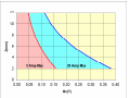
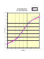
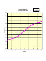
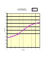
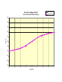
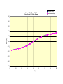
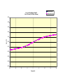
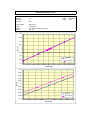
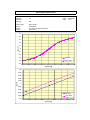
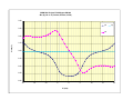
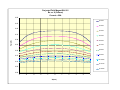
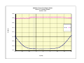
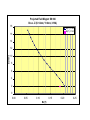
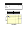
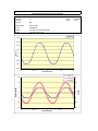
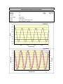
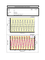
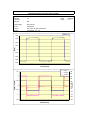
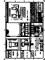
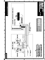
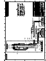
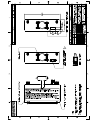
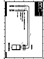
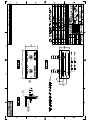
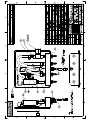
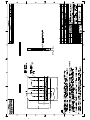
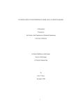
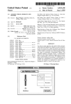
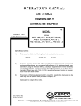
GMW
USER’S MANUAL
MODEL: 5201
PROJECTED FIELD ELECTROMAGNET
Date Sold:____________
Serial number: ________
PROPRIETARY
THIS DOCUMENT CONTAINS CONFIDENTIAL INFORMATION PROPRIETARY TO GMW ASSOCIATES. IT
MUST NOT BE REPRODUCED OR DISCLOSED TO OTHERS OR USED IN ANY WAY EXCECPT FOR THE
INSTALLATION, OPERATION OR MAINTENANCE OF GMW ASSOCIATES PRODUCTS.
File No: MX9-07-5201_E_Proj_Field_Magnet_Nov_21_2011.doc
Revision Date: 21 Nov, 2011
_________________________________________________________________________________
GMW
955 Industrial Road, San Carlos, CA 94070 Tel: (650) 802-8292
Email: [email protected] Web site: www.gmw.com
Fax: (650) 802-8298
TABLE OF CONTENTS
SPECIFICATIONS
5201 Electromagnet Specifications
WARNINGS
Section 1
[ Refer to this section before operation of Electromagnet System ] Section 2
INSTALLATION
Mounting Position
Electrical Connections
Electrical Interlocks
Water Cooling
Section 3
OPERATION
Section 4
MAINTENANCE
Section 5
EXCITATION CURVES
Field versus Current
Hysteresis
Section 6
TEST DATA
Field Uniformity
AC Operation
Section 7
DRAWINGS
Drawing 11901860 Electromagnet General Assembly
Drawing 11902010 Electromagnet Wiring
Drawing 11902000 Electromagnet Electrical Assembly
Drawing 13900420 Electromagnet Electrical Wiring.
Drawing 13900430 Electrical Wiring, Kepco Programming Plug, Electrical
Drawing 1190700250 Electrical Wiring, Kepco Programming Plug, Mechanical
Drawing 11901970 Electromagnet Cooling System
Drawing 11902020 Electromagnet Water I/O Manifold
Drawing 11902480-S1 Water Control Panel, General Assembly
Drawing 11902480-S2 Water Control Panel, General Assembly, Internal
Drawing 11902130 Electromagnet Alignment Plate
Section 8
Section 1
SPECIFICATIONS
Model: 5201 Electromagnet Specifications
Projected Field: (at max current of 20A)
Projected Field Region (for Bx)
(for Bz)
Coil:
coil resistance (20°C)
max resistance (hot)*
max power (water cooling)
max power (ambient air cooling)
Bx= ±0.3T (3000G)
(X,Y,Z = 0, 0, 4mm)
Bz= ±0.2T (2000G)
(X,Y,Z = 14, 0, 4mm)
X = 0mm
Y = -5 to + 5mm
Z = 0 to 12mm
X = ± 14mm
Y = 0mm
Z = 0 to 12mm
0.85 Ohm
1.02 Ohm
20A/20V (400W)
5A/5V (25W)
Self Inductance:
Approx 40mH at 1 Hz
(The apparent inductance reduces with frequency due to eddy currents in the solid poles)
Cooling: (measured at water I/O manifold)
Thermal Interlock:
Dimensions:
Mass:
1.0 Liter/min, 2.0 bar [0.26 USG/min, 28 psid]
Open circuit above 75° C (167° F)
Drawing 11901860
70.0 mm W x 60.0 mm D x 120 mm H
2.8 inch W x 2.4 inch D x 4.7 inch H
2.1 kg (4.6 lb)
*CAUTION - The value of maximum coil resistance given should not be exceeded.
At this resistance the coils are at maximum safe temperature for continuous operation.
Section 2
WARNINGS
REFER TO WARNINGS BELOW BEFORE OPERATING ELECTROMAGNET
SYSTEM
1
Personnel Safety
In operation the m agnet fringing field in the vi cinity of the pole gap is in excess of 0.5m T
(5G). This can cause m alfunctioning of sensitive electronic and magnetic components. We
recommend that warning signs are posted indicating that a magnetic field may be present.
2
Ferromagnetic Objects
During operation the magnet exerts magnetic attraction towards ferromagnetic objects in the
near vicinity of its pole faces. Keep ferromagnetic items clear!
3
Arcing
This magnet stores energy in its field during operation. Do not disconnect any current lead
while under load or the m agnetic field energy will be discharged across the interruption
causing arcing and possible damage to electronic circuits.
4
Coil Hot Resistance
Do not exceed the m aximum coil hot resist ance given in the specifications or coil
overheating and possible damage may occur
5
Watches, Credit Cards, and Magnetic Disks
Do not m ove magnetically sensitive item s into the close vicinity of the m agnet pole gap.
Even some anti-magnetic watches can be dam aged when placed in close proxim ity to the
pole gaps during operation. Credit cards, and m agnetic disks are affected by m agnetic fields
as low as 0.5m T (5G). Depending on the previous operating field and the pole gap, the
remanent field in the gap can be in excess of 0.5mT (5G) with the m agnet power supply off
or disconnected.
6
Power Supply
Refer to the power supply manufacturers manual for additional important safety information.
Section 3
INSTALLATION
Mounting Position (Refer to drawing 11902050)
The magnet system can be m ounting in any orie ntation, including being com pletely inverted.
Four M3 clearance holes are provided on the magnet transition plate for mounting the magnet.
Electrical Connections
The magnet system comes with integrated wiring for the m agnet. Never connect or rem ove
cables from the magnet system with the DC pow er energized otherwise dam age to the m agnet
power supply may occur. Follow instruction below for making electrical connections.
Power Supply (Refer to drawing 11902000 & 13900420)
1. Firstly ensure the power supply is turned off and the AC power cable is disconnected.
2. Plug in the magnet cable plug into the back of Kepco BOP power supply.
3. Secure the connecting plug with the two securing thumbscrews.
4. Connect the three sleeved wires to the output connector block on the rear of the Kepco
BOP power supply as detailed below.
• Black Wire with Red sleeve to Output
• Black Wire with Blue sleeve to Common
• Green wire to Ground
Note: Reconnect AC power cable to power supply . The magnet system is now ready to use. Do
not power up the magnet unless the cooling water is turned on and flowing at 1.0 liters/min.
Electrical Interlocks
The Model 5201 has two thermostats, Selco part no 802L-075. They are located on the pole/coil
assembly heatsinks and wired in series. The thermostats are normally closed, opening when the
coil heatsink temperature exceeds 75° C, +/- 5° C.
Water Cooling (Refer to drawing 11902000)
The Model 5201 can be operated to an average coil temperature of 70° C. Assuming an ambient
laboratory temperature of 20° C and a tem perature coefficient of resistively for copper of
0.0039/° C, the hot resistance of the coil shoul
d not exceed 20% m ore than the am bient
temperature "cold" resistance. The coil ther mostat will open when either pole/coil heatsink
temperature exceeds approximately 75° C. If either tem perature switch opens then the Magnet
power supply circuit breaker will trip to the off position. Clean, cool (16° C - 20° C) water at
1.0l/min at 1.0 bar (28 psid) should be used to cool the 5201 magnet.
The cooling copper tubes are electrically isolat ed from the coils to avoid electrochem ical
corrosion. A 50 micron filter should be placed before the input to the magnet to trap particulates
and avoid blockage of the cooling circuits.
Water Cooling Connections
The magnet is supplied with two 3.0m m (1/8”) I.D. 1 meter long flexible hoses that connected
the water cooling circuit to the hose couplings on the rear of the W ater I/O Manifold. On the
front of the W ater I/O Manifold are two barbed “push on” hose couplings to suit 6 m m (1/4”)
I.D. rubber hose.
•
•
Water Inlet: Connect to a clean water source fitted with a suitable metering valve
(to control water flow).
Water Outlet: Connect to drain.
Inlet Water Metering Valve Kit.
Metering Valve (brass)
required)
Hex Nipple (brass) 1/8” NPT female
Hose Push on (black) ¼” I.D.
required)
SWAGELOCK Cat No: B-4MG4-MH (1
SWAGELOCK Cat No: B-2-CN (1 required)
SWAGELOCK Cat No: PB-4-BK (as
Water Control Panel, Part 11902480.
GMW offers an optional W ater Control Panel for users that have a suitable supply of cooling
water. The 11902480 includes a water filter, flow c ontrol, flow indicator and flow interlock in
one package. Since the therm al capacity of the Model 5201 Electrom agnet is sm all it is
particularly important to have the correct wa ter flow to avoid overheating. A water flow
interlock ensures that the Power Supply for the 5201 will not provide current unless both the
water flow and coil temperature interlocks are in the closed (safe) position.
Section 4
OPERATION
Electromagnet System (Kepco Power Supply operating in Current Control)
1. Set Voltage and Current toggle switches to off before turning on power m ain circuit
breaker.
2. Set Current control potentiom eter to fully counterclockwise position. Turn the
potentiometer clockwise five turns. This position is approximately equal to a zero current
setting.
3. Select Mode switch to Current.
4. Turn on power supply main circuit breaker.
5. Turn on Current control toggle switch
6. Turn the Current control potentiom
eter clockwise f or positive current or
counterclockwise for negative current as required.
Section 5
MAINTENANCE
Electrical Connections on the magnet terminal block should be check annually. The electrical
connections should be clean and tight. Discoloration is a sign that the connection is overheating
and must be rectified before further use of the magnet.
Water Hoses should be checked regularly for water leaks. Any leaks should be rectified before
further use of the magnet.
Section 6
EXCITATION CURVES
Upward Ramp
Projected Field Magnet SN:001
Bx vs. Current (X=Y=0mm, Z=2mm)
Downward Ramp
0.50
0.40
0.30
0.20
Field (T)
0.10
0.00
-0.10
-0.20
-0.30
-0.40
-0.50
-20
-15
-10
-5
0
Current(A)
5
10
15
20
Upward Ramp
Projected Field Magnet SN:001
Bx vs. Current (X=Y=0mm, Z=3mm)
Downward Ramp
0.50
0.40
0.30
0.20
Field (T)
0.10
0.00
-0.10
-0.20
-0.30
-0.40
-0.50
-20
-15
-10
-5
0
Current (A)
5
10
15
20
Upward Ramp
Projected Field Magnet SN:001
Bx vs. Current (X=Y=0mm, Z=4mm)
Downward Ramp
0.50
0.40
0.30
0.20
Field (T)
0.10
0.00
-0.10
-0.20
-0.30
-0.40
-0.50
-20
-15
-10
-5
0
Current (A)
5
10
15
20
Upward Ramp
Projected Field Magnet SN:001
Bx vs. Current (X=Y=0mm, Z=5mm)
Downward Ramp
0.50
0.40
0.30
0.20
Field (T)
0.10
0.00
-0.10
-0.20
-0.30
-0.40
-0.50
-20
-15
-10
-5
0
Current (A)
5
10
15
20
Upward Ramp
Projected Field Magnet SN:001
Bx vs. Current (X=Y=0mm, Z=6mm)
Downward Ramp
0.50
0.40
0.30
0.20
Field (T)
0.10
0.00
-0.10
-0.20
-0.30
-0.40
-0.50
-20
-15
-10
-5
0
Current (A)
5
10
15
20
Upward Ramp
Projected Field Magnet SN:001
Bx vs. Current (X=Y=0mm, Z=7mm)
Downward Ramp
0.50
0.40
0.30
0.20
Field (T)
0.10
0.00
-0.10
-0.20
-0.30
-0.40
-0.50
-20
-15
-10
-5
0
Current (A)
5
10
15
20
Upward Ramp
Downward Ramp
Projected Field Magnet SN:001
Bx vs. Current (X=Y=0mm, Z=8mm)
0.50
0.40
0.30
0.20
Field (T)
0.10
0.00
-0.10
-0.20
-0.30
-0.40
-0.50
-20
-15
-10
-5
0
Current (A)
5
10
15
20
Upward Ramp
Downward Ramp
Projected Field Magnet SN:001
Bx vs. Current (X=Y=0mm, Z=9mm)
0.50
0.40
0.30
0.20
Field (T)
0.10
0.00
-0.10
-0.20
-0.30
-0.40
-0.50
-20
-15
-10
-5
0
Current (A)
5
10
15
20
Upward Ramp
Projected Field Magnet SN:001
Bx vs. Current (X=Y=0mm, Z=10mm)
Downward Ramp
0.50
0.40
0.30
0.20
Field (T)
0.10
0.00
-0.10
-0.20
-0.30
-0.40
-0.50
-20
-15
-10
-5
0
Current (A)
5
10
15
20
GMW ASSOCIATES
Electromagnet Hysteresis Plot
Model:
Serial No:
Pole Face:
Pole gap:
5201
15
Engr:
Date:
Page:
Power Supply:
PS SN:
Position:
Current:
Kepco 20-5
147743 R15
X=Y=0mm, Z= 2mm above pole
-5A~+5A
N/A
Y.Q.
12/16/2005
2 of 2
0.2
0.15
0.1
Bx (T)
0.05
0
-0.05
-0.1
Up Ramp
-0.15
-0.2
Down Ramp
-5
-4
-3
-2
-1
0
1
Current (A)
2
3
4
5
0.01
0.008
0.006
0.004
Bx (T)
0.002
0
-0.002
-0.004
-0.006
Up Ramp
-0.008
-0.01
-0.2
Down Ramp
-0.15
-0.1
-0.05
0
Current (A)
0.05
0.1
0.15
0.2
GMW ASSOCIATES
Electromagnet Hysteresis Plot
Model:
Serial No:
Pole Face:
Pole gap:
5201
15
Engr:
Date:
Page:
Power Supply:
PS SN:
Position:
Current:
Kepco 20-20
155399 R31
X=Y=0mm, Z= 2mm above pole
-20A~+20A
N/A
Y.Q.
12/16/2005
1 of 2
0.5
0.4
0.3
0.2
Bx (T)
0.1
0
-0.1
-0.2
-0.3
Up Ramp
-0.4
Down Ramp
-0.5
-20
-15
-10
-5
0
Current (A)
5
10
15
20
0.01
0.008
0.006
0.004
Bx (T)
0.002
0
-0.002
-0.004
-0.006
Up Ramp
-0.008
-0.01
-0.2
Down Ramp
-0.15
-0.1
-0.05
0
Current (A)
0.05
0.1
0.15
0.2
Section 7
TEST DATA
GMW 5201 Project Field Magnet SN:004
-Bx, By, Bz vs. X (Y=0mm, Z=2mm, I=15A)
0.40
Bx
By
0.30
Bz
0.20
Field (T)
0.10
0.00
-0.10
-0.20
-0.30
-0.40
-20
-15
-10
-5
0
X (mm)
5
10
15
20
Projected Field Magnet SN: 001
Bx vs. X (Y=0mm)
Current = 20A
0.50
Z=2mm
0.45
Z=3mm
0.40
Z=4mm
Field(T)
0.35
Z=5mm
0.30
Z=6mm
0.25
Z=7mm
0.20
Z=8mm
Z=9mm
0.15
Z=10mm
0.10
Z=11mm
0.05
Z=12mm
0.00
-5
-4
-3
-2
-1
0
X(mm)
1
2
3
4
5
Projected Field Magnet SN: 001
Bz vs. X (Y=0mm)
Current = 20A
0.50
Z=2mm
0.40
Z=3mm
0.30
Z=4mm
Field(T)
0.20
Z=5mm
0.10
Z=6mm
0.00
Z=7mm
-0.10
Z=8mm
Z=9mm
-0.20
Z=10mm
-0.30
Z=11mm
-0.40
-0.50
Z=12mm
-5
-4
-3
-2
-1
0
X(mm)
1
2
3
4
5
GMW 5201 Project Field Magnet SN:004
-Bx, Bz vs. Y (X=0mm, Z=2mm
Current = 15A
0.05
0.00
-0.05
Field (T)
-0.10
Bx
Bz
-0.15
-0.20
-0.25
-0.30
-0.35
-20
-15
-10
-5
0
Y (mm)
5
10
15
20
Projected Field Magnet SN:004
Bz vs. Z (X=14mm, Y=0mm, I=18A)
18
Bz(T), I=18A
Bz(T), I=15A
16
14
Z(mm)
12
10
8
6
4
2
0
0.00
0.05
0.10
0.15
Bz(T)
0.20
0.25
GMW ASSOCIATES
5201 Electromagnet Inductance
Model:
Serial No:
Pole Face:
Pole gap:
5201
15
Engr:
Date:
Page:
N/A
Power Supply:
PS SN:
Position:
Current:
Y.Q.
12/16/2005
1 of 1
X=Y=0mm, Z= 2mm above pole
1Hz, 2Hz, 5Hz, 10Hz, sine
Current Frequency (Hz)
1
2
5
10
Inductance(mH)
50
42
41
35
60
Inductance (mH)
50
40
30
20
10
0
0
2
4
6
Current Frequency (Hz)
8
10
GMW ASSOCIATES
Electromagnet Bx vs Frequency (sine wave) Plot
Model:
Serial No:
Pole Face:
Pole gap:
5201
15
Engr:
Date:
Page:
Power Supply:
Power Supply:
Position:
Current:
Kepco 20-20
PS SN:
Kepco 50-8
PS SN:
X=Y=0mm, Z= 2mm above pole
Sine, before visual distortion of sine waveform
N/A
Frequency(Hz)
1
2
5
10
20
50
100
Kepco 50-8
0.2341
0.2307
0.2208
0.2043
0.1805
0.1401
0.0867
Y.Q.
12/16/2005
1 of 1
155399 R31
154897 R24
Kepco 20-20
0.2785
0.2408
0.2307
0.2025
0.1479
0.0681
0.0331
Kepco 50-8
0.3
Kepco 20-20
0.25
Bx(T)
0.2
0.15
0.1
0.05
0
1
10
Frequency(Hz)
100
GMW ASSOCIATES
5201 Electromagnet 1Hz sine wave waveform
Model:
Serial No:
Pole Face:
Pole gap:
5201
15
Engr:
Date:
Page:
Power Supply:
PS SN:
Position:
Current:
Kepco 20-20
155399 R31
X=Y=0mm, Z= 2mm above pole
1Hz sine, -10A~+10A
N/A
Y.Q.
12/2/2005
1 of 1
Bx(T)
0.4
0.3
0.2
Bx(T)
0.1
0
-0.1
-0.2
-0.3
0
0.5
1
Time(second)
1.5
Vp(V)
15
15
Iout(A)
Vout(V)
10
Vp(V), Iout(A)
2
10
5
5
0
0
-5
-5
-10
-10
-15
0
0.5
1
Time(second)
1.5
2
-15
Vout(V)
-0.4
GMW ASSOCIATES
5201 Electromagnet 10Hz sine wave waveform
Model:
Serial No:
Pole Face:
Pole gap:
5201
15
Engr:
Date:
Page:
N/A
Power Supply:
PS SN:
Position:
Current:
Kepco 20-20
155399 R31
X=Y=0mm, Z= 2mm above pole
10Hz sine, -8A~+8A
Y.Q.
12/2/2005
1 of 1
Bx(T)
0.25
0.2
0.15
0.1
Bx(T)
0.05
0
-0.05
-0.1
-0.15
-0.2
-0.25
0
0.2
0.4
0.6
Time(second)
0.8
1
Vp(V)
15
20
Iout(A)
Vout(V)
10
15
5
5
0
0
Vout(V)
Vp(V), Iout(A)
10
-5
-5
-10
-10
-15
-15
0
0.2
0.4
0.6
Time(second)
0.8
1
-20
GMW ASSOCIATES
5201 Electromagnet 50Hz sine wave waveform
Model:
Serial No:
Pole Face:
Pole gap:
5201
15
Engr:
Date:
Page:
Power Supply:
PS SN:
Position:
Current:
Kepco 50-8
154897 R24
X=Y=0mm, Z= 2mm above pole
50Hz, sine wave, -7A~+7A
N/A
Y.Q.
12/13/2005
1 of 1
Bx(T)
0.2
0.15
0.1
Bx(T)
0.05
0
-0.05
-0.1
-0.15
-0.2
0
0.02
0.04
0.06
0.08
0.1
Time(second)
Iout(A)
Vp(V), Iout(A)
8
Vout(V)
50
40
6
30
4
20
2
10
0
0
-2
-10
-4
-20
-6
-30
-8
-40
-10
0
0.02
0.04
0.06
Time(second)
0.08
0.1
-50
Vout(V)
Vp(V)
10
GMW ASSOCIATES
5201 Electromagnet 100Hz sine wave waveform
Model:
Serial No:
Pole Face:
Pole gap:
5201
15
Engr:
Date:
Page:
Power Supply:
PS SN:
Position:
Current:
Kepco 50-8
154897 R24
X=Y=0mm, Z= 2mm above pole
100Hz, sine wave, -5A~+5A
N/A
Y.Q.
12/13/2005
1 of 1
Bx(T)
0.12
0.1
0.08
0.06
0.04
Bx(T)
0.02
0
-0.02
-0.04
-0.06
-0.08
-0.1
0
0.02
0.04
0.06
0.08
0.1
Time(second)
Vp(V)
10
60
Iout(A)
8
Vout(V)
6
20
2
0
0
-2
-20
-4
-6
-40
-8
-10
0
0.02
0.04
0.06
Time(second)
0.08
0.1
-60
Vout(V)
Vp(V), Iout(A)
4
40
GMW ASSOCIATES
5201 Electromagnet 1Hz square wave waveform
Model:
Serial No:
Pole Face:
Pole gap:
5201
15
Engr:
Date:
Page:
Power Supply:
PS SN:
Position:
Current:
Kepco 20-20
155399 R31
X=Y=0mm, Z= 2mm above pole
1Hz square, -1A~+1A
N/A
Y.Q.
12/2/2005
1 of 1
Bx(T)
0.04
0.03
0.02
Bx(T)
0.01
0
-0.01
-0.02
-0.03
-0.04
0
0.5
1
1.5
2
Time(second)
Vp(V)
1.5
25
Vout(V)
1
20
15
0.5
10
Vout(V)
Vp(V), Iout(A)
30
Iout(A)
5
0
0
-5
-0.5
-10
-15
-1
-20
-1.5
0
0.5
1
Time(second)
1.5
2
-25
GMW ASSOCIATES
5201 Electromagnet 1Hz square wave waveform
Model:
Serial No:
Pole Face:
Pole gap:
5201
15
Engr:
Date:
Page:
N/A
Power Supply:
PS SN:
Position:
Current:
Kepco 20-20
155399 R31
X=Y=0mm, Z= 2mm above pole
1Hz square, -20A~+20A
Y.Q.
12/2/2005
1 of 1
Bx(T)
0.5
0.4
0.3
0.2
Bx(T)
0.1
0
-0.1
-0.2
-0.3
-0.4
0
0.5
1
Time (second)
1.5
2
Vp(V)
25
30
Iout(A)
20
Vout(V)
20
15
Vp(V), Iout(A)
10
10
5
0
0
-5
-10
-10
-15
-20
-20
-25
Vout(V)
-0.5
0
0.5
1
Time (second)
1.5
2
-30
GMW ASSOCIATES
5201 Electromagnet 10Hz square wave waveform
Model:
Serial No:
Pole Face:
Pole gap:
5201
15
Engr:
Date:
Page:
Power Supply:
PS SN:
Position:
Current:
Kepco 50-8
154897 R24
X=Y=0mm, Z= 2mm above pole
10Hz, square wave, -4A~+4A
N/A
Y.Q.
12/13/2005
1 of 1
Bx(T)
0.15
0.1
Bx(T)
0.05
0
-0.05
-0.1
-0.15
0
0.2
0.4
0.6
Time(second)
0.8
1
Vp(V)
8
60
Iout(A)
6
Vout(V)
40
20
2
0
0
-2
-20
-4
-40
-6
-8
0
0.2
0.4
0.6
Time(second)
0.8
1
-60
Vout(V)
Vp(V), Iout(A)
4
Section 8
DRAWINGS