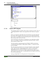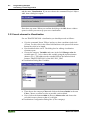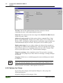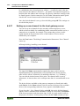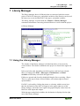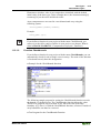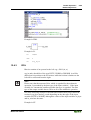
1
Programming Tool IEC 61131-3
WAGO-I/O-I/O-PRO 32
Manual Part 1
Technical description
Chapter 1 - 14
759-122/000-002
Version 2.0.0
ii •
General
Copyright ã 2003 by WAGO Kontakttechnik GmbH
All rights reserved.
WAGO Kontakttechnik GmbH
Hansastraße 27
D-32423 Minden
Phone: +49 (0) 571/8 87 – 0
Fax:
+49 (0) 571/8 87 – 1 69
E-Mail: [email protected]
Web:
http://www.wago.com
Technical Support
Phone: +49 (0) 571/8 87 – 5 55
Fax:
+49 (0) 571/8 87 – 85 55
E-Mail: [email protected]
Every conceivable measure has been taken to ensure the correctness and
completeness of this documentation. However, as errors can never be fully
excluded we would appreciate any information or ideas at any time.
E-Mail: [email protected]
We wish to point out that the software and hardware terms as well as the
trademarks of companies used and/or mentioned in the present manual are
generally trademark or patent protected.
WAGO-I/O-SYSTEM 759
WAGO-I/O-PRO 32
Table of Contents
• iii
TABLE OF CONTENTS
1 Important Comments ................................................................................ 1
1.1 Legal Principles ........................................................................................... 1
1.1.1
Copyright .......................................................................................... 1
1.1.2
Personnel Qualification .................................................................... 1
1.1.3
Intended Use ..................................................................................... 1
1.2 Symbols........................................................................................................ 2
1.3 Font Conventions ......................................................................................... 3
1.4 Number Notation ......................................................................................... 3
1.5 Scope............................................................................................................ 4
1.6 Abbreviations............................................................................................... 4
1.7 Scope of Delivery ........................................................................................ 5
1.8 System Configuration .................................................................................. 5
1.9 Installation.................................................................................................... 6
1.10 Uninstall................................................................................................. 7
1.11 Start ........................................................................................................ 8
1.12 Important Informations .......................................................................... 9
2 WAGO-I/O-PRO 32 V2.2 Overview ...................................................... 10
2.1 What is WAGO-I/O-PRO 32 ..................................................................... 10
2.2 Overview of WAGO-I/O-PRO 32 Functions ............................................ 10
2.2.1
How is a project structured? ........................................................... 10
2.2.2
How do I set up my project?........................................................... 10
2.2.3
How can I test my project? ............................................................. 10
2.2.4
Debugging....................................................................................... 11
2.2.5
Additional Online Functions........................................................... 11
2.2.6
Additional WAGO-I/O-PRO 32 Features ...................................... 11
2.2.7
Summary......................................................................................... 11
2.3 Project Components ................................................................................... 11
2.3.1
Project ............................................................................................. 11
2.3.2
POU (Program Organization Unit)................................................. 12
2.3.3
Function .......................................................................................... 12
2.3.4
Function Block................................................................................ 14
2.3.5
Function Block Instances................................................................ 14
2.3.6
Calling a function block.................................................................. 16
2.3.7
Program........................................................................................... 17
2.3.8
PLC_PRG ....................................................................................... 19
2.3.9
Action ............................................................................................. 19
2.3.10
Resources........................................................................................ 21
2.3.11
Libraries.......................................................................................... 21
2.3.12
Data types ....................................................................................... 21
2.3.13
Visualization................................................................................... 21
2.4 Languages .................................................................................................. 21
2.4.1
Instruction List (IL) ........................................................................ 21
2.4.2
Structured Text (ST) ....................................................................... 24
2.4.3
Sequential Function Chart (SFC).................................................... 32
2.4.4
Function Block Diagram (FBD) ..................................................... 39
2.4.5
The Continuous Function Chart Editor (CFC) ............................... 39
WAGO-I/O-SYSTEM 759
WAGO-I/O-PRO 32
iv •
Table of Contents
2.4.6
Ladder Diagram (LD) ..................................................................... 40
2.5 Debugging, Online Functions .................................................................... 42
2.5.1
Sampling Trace............................................................................... 42
2.5.2
Debugging....................................................................................... 42
2.5.3
Breakpoint....................................................................................... 42
2.5.4
Single step....................................................................................... 42
2.5.5
Single Cycle.................................................................................... 43
2.5.6
Change values online...................................................................... 43
2.5.7
Monitoring ...................................................................................... 43
2.5.8
Simulation....................................................................................... 44
2.5.9
Log.................................................................................................. 45
2.6 The Standard .............................................................................................. 45
3 Programming Example ........................................................................... 46
3.1 Controlling a Traffic Signal Unit............................................................... 46
3.1.1
Create POU..................................................................................... 46
3.1.2
What does TRAFFICSIGNAL do? ................................................ 46
3.1.3
What does WAIT do? ..................................................................... 46
3.1.4
What does SEQUENCE do?........................................................... 46
3.1.5
What does PLC_PRG do? .............................................................. 47
3.1.6
"TRAFFICSIGNAL" declaration ................................................... 47
3.1.7
"TRAFFICSIGNAL" body............................................................. 47
3.1.8
Connecting the standard.lib ............................................................ 49
3.1.9
"WAIT" declaration........................................................................ 50
3.1.10
"WAIT" body.................................................................................. 50
3.1.11
"SEQUENCE" first expansion level............................................... 51
3.1.12
Create a SFC diagram ..................................................................... 52
3.1.13
Actions and transition conditions ................................................... 53
3.1.14
"SEQUENCE" second expansion level .......................................... 55
3.1.15
The result ........................................................................................ 57
3.1.16
PLC_PRG ....................................................................................... 57
3.1.17
TRAFFICSIGNAL simulation ....................................................... 59
3.2 Visualizing a Traffic Signal Unit............................................................... 59
3.2.1
Creating a new visualization........................................................... 59
3.2.2
Insert element in Visualization ....................................................... 60
3.2.3
The other traffic lights .................................................................... 61
3.2.4
The TRAFFICSIGNAL case .......................................................... 61
3.2.5
The second traffic signal................................................................. 62
3.2.6
The ON switch................................................................................ 62
3.2.7
Font in the visualization.................................................................. 63
4 Components of WAGO-I/O-PRO 32...................................................... 64
4.1 The Main Window ..................................................................................... 64
4.1.1
Menu bar......................................................................................... 64
4.1.2
Tool bar........................................................................................... 65
4.1.3
Object Organizer............................................................................. 65
4.1.4
Screen divider ................................................................................. 66
4.1.5
Work space ..................................................................................... 66
4.1.6
Message window ............................................................................ 66
4.1.7
Status bar ........................................................................................ 66
WAGO-I/O-SYSTEM 759
WAGO-I/O-PRO 32
Table of Contents
• v
4.1.8
Context Menu ................................................................................. 67
4.2 Options....................................................................................................... 67
4.2.1
'Project' 'Options' ............................................................................ 68
4.2.2
Options for Load & Save................................................................ 68
4.2.3
Options for User information.......................................................... 69
4.2.4
Options for Editor ........................................................................... 70
4.2.5
Options for the Desktop.................................................................. 73
4.2.6
Options for Colors .......................................................................... 74
4.2.7
Options for Directories ................................................................... 75
4.2.8
Options for Log............................................................................... 76
4.2.9
Options for Build ............................................................................ 77
4.2.10
Passwords ....................................................................................... 79
4.2.11
'Sourcedownload' ............................................................................ 80
4.2.12
Options for 'Symbol Configuration'................................................ 81
4.2.13
Options for 'Macros'........................................................................ 83
4.3 Managing Projects ..................................................................................... 84
4.3.1
'File' 'New'....................................................................................... 84
4.3.2
'File' 'Open'...................................................................................... 84
4.3.3
'File' 'Close' ..................................................................................... 85
4.3.4
'File' 'Save' ...................................................................................... 85
4.3.5
'File' 'Save as' .................................................................................. 86
4.3.6
'File' 'Save/Mail Archive'................................................................ 87
4.3.7
'File' 'Print' ...................................................................................... 90
4.3.8
'File' 'Printer setup'.......................................................................... 91
4.3.9
'File' 'Exit'........................................................................................ 93
4.3.10
'Project' 'Build' ................................................................................ 93
4.3.11
'Project' 'Rebuild all' ....................................................................... 94
4.3.12
'Project' 'Clean all'........................................................................... 94
4.3.13
'Project' 'Load Download-Information'........................................... 94
4.3.14
'Project' 'Translate into another language'....................................... 94
4.3.15
'Project' 'Document' ...................................................................... 100
4.3.16
'Project' 'Export' ............................................................................ 101
4.3.17
'Project' 'Import' ............................................................................ 101
4.3.18
'Project' 'Merge'............................................................................. 102
4.3.19
'Project' 'Compare' ........................................................................ 102
4.3.20
'Project' 'Project info' .................................................................... 107
4.3.21
'Project' 'Global Search' ................................................................ 109
4.3.22
'Project' 'Global replace'................................................................ 110
4.3.23
'Project' 'Check'............................................................................. 110
4.3.24
'Project' 'Passwords for user groups' ............................................. 112
4.4 Managing Objects in a Project................................................................. 113
4.4.1
Object............................................................................................ 113
4.4.2
Folder............................................................................................ 113
4.4.3
'New Folder'.................................................................................. 114
4.4.4
'Expand nodes' 'Collapse nodes'.................................................... 114
4.4.5
'Project' 'Object Delete' ................................................................. 115
4.4.6
'Project' 'Object Add'..................................................................... 115
4.4.7
'Project' 'Object Rename' .............................................................. 116
4.4.8
'Project' 'Object Convert'............................................................... 116
4.4.9
'Project' 'Object Copy'................................................................... 117
WAGO-I/O-SYSTEM 759
WAGO-I/O-PRO 32
vi •
Table of Contents
4.4.10
'Project' 'Object Open'................................................................... 117
4.4.11
'Project' 'Object Access rights' ...................................................... 118
4.4.12
'Project' 'Object properties' ........................................................... 119
4.4.13
'Project' 'Add Action' .................................................................... 119
4.4.14
'Project' 'Open Instance' ................................................................ 119
4.4.15
'Project' 'Show Call Tree' .............................................................. 120
4.4.16
'Projekt' 'Show cross reference'..................................................... 120
4.5 General Editing Functions ....................................................................... 121
4.5.1
'Edit' 'Undo'................................................................................... 121
4.5.2
'Edit' 'Redo' ................................................................................... 122
4.5.3
'Edit' 'Cut' ...................................................................................... 122
4.5.4
'Edit' 'Copy' ................................................................................... 123
4.5.5
'Edit' 'Paste' ................................................................................... 123
4.5.6
'Edit' 'Delete" ................................................................................ 124
4.5.7
'Edit' 'Find' .................................................................................... 125
4.5.8
'Edit' 'Find next'............................................................................. 125
4.5.9
'Edit' 'Replace'............................................................................... 126
4.5.10
'Edit' 'Input Assistant'.................................................................... 126
4.5.11
'Edit''Declare Variable'.................................................................. 129
4.5.12
'Edit' 'Next error'".......................................................................... 129
4.5.13
'Edit' 'Previous error'" ................................................................... 130
4.5.14
'Edit' 'Macros'................................................................................ 130
4.6 General Online Functions ........................................................................ 130
4.6.1
'Online-Change' Functionality ...................................................... 130
4.6.2
'Online' 'Login' .............................................................................. 131
4.6.3
If the system reports...................................................................... 131
4.6.4
'Online' 'Logout' ............................................................................ 132
4.6.5
'Online' 'Download'....................................................................... 132
4.6.6
'Online' 'Run'................................................................................. 133
4.6.7
'Online' 'Stop' ................................................................................ 133
4.6.8
'Online' 'Reset'............................................................................... 133
4.6.9
'Online' 'Reset (cold)' .................................................................... 133
4.6.10
'Online' 'Reset (original)'............................................................... 134
4.6.11
'Online' 'Toggle Breakpoint' ......................................................... 134
4.6.12
'Online' 'Breakpoint Dialog Box' .................................................. 134
4.6.13
'Online' 'Step over' ........................................................................ 135
4.6.14
'Online' 'Step in' ............................................................................ 135
4.6.15
'Online' 'Single Cycle' ................................................................... 136
4.6.16
'Online' 'Write values' ................................................................... 136
4.6.17
'Online' 'Force values' ................................................................... 137
4.6.18
'Online' 'Release force'.................................................................. 138
4.6.19
'Online' 'Write/Force' Dialog'........................................................ 139
4.6.20
'Online' 'Show Call Stack'............................................................. 141
4.6.21
'Online' 'Flow Control'"................................................................. 141
4.6.22
'Online' 'Simulation' ...................................................................... 142
4.6.23
'Online' 'Communication Parameters' ........................................... 142
4.6.24
Principle of a gateway system ...................................................... 142
4.6.25
What the communications parameters dialog on the local PC shows143
4.6.26
Setting up the desired gateway server and channel ...................... 144
4.6.27
Setting up a new channel for the local gateway server................. 146
WAGO-I/O-SYSTEM 759
WAGO-I/O-PRO 32
Table of Contents
• vii
4.6.28
Tips for editing the parameters in the communications parameters
dialogue......................................................................................... 147
4.6.29
Quick check in the event of unsuccessful connection attempt to the
gateway......................................................................................... 147
4.6.30
'Online' 'Sourcecode download' .................................................... 148
4.6.31
'Online' 'Create bootproject'.......................................................... 148
4.6.32
'Online' 'Write file to controller' ................................................... 148
4.6.33
'Online' 'Load file from controller'................................................ 148
4.7 Log ........................................................................................................... 149
4.7.1
'Window' 'Log' .............................................................................. 149
4.7.2
Menu Log...................................................................................... 150
4.7.3
Storing the project log .................................................................. 151
4.8 Window set up ......................................................................................... 151
4.8.1
'Window' 'Tile Horizontal' ............................................................ 151
4.8.2
'Window' 'Tile Vertical' ................................................................ 152
4.8.3
'Window' 'Cascade' ....................................................................... 152
4.8.4
'Window' 'Arrange Symbols'......................................................... 152
4.8.5
'Window' 'Close All' ..................................................................... 152
4.8.6
'Window' 'Messages' ..................................................................... 152
4.9 Help when you need it ............................................................................. 152
4.9.1
'Help' 'Contents and Index'............................................................ 152
4.9.2
Main Help Window ...................................................................... 153
4.9.3
Index Window .............................................................................. 154
4.9.4
Context Sensitive Help ................................................................. 155
5 The Editors ............................................................................................. 156
5.2 Declaration Editor.................................................................................... 157
5.2.1
Declaration Part ............................................................................ 157
5.2.2
Input Variable ............................................................................... 158
5.2.3
Output Variable ............................................................................ 158
5.2.4
Input and Output Variables........................................................... 158
5.2.5
Local Variables............................................................................. 159
5.2.6
Remanent variables....................................................................... 159
5.2.7
Constants, Typed Literals ............................................................. 160
5.2.8
External variables ......................................................................... 160
5.2.9
Keywords...................................................................................... 161
5.2.10
Variables declaration .................................................................... 161
5.2.11
AT Declaration ............................................................................. 162
5.2.12
'Insert' 'Declarations keywords'..................................................... 162
5.2.13
'Insert' 'Type' ................................................................................. 162
5.2.14
Syntax Coloring............................................................................ 163
5.2.15
Shortcut Mode .............................................................................. 163
5.2.16
Autodeclaration............................................................................. 164
5.2.17
Line Numbers in the Declaration Editor....................................... 166
5.2.18
Declarations as tables ................................................................... 166
5.2.19
'Insert' 'New Declaration' .............................................................. 167
5.2.20
Pragma instructiion....................................................................... 167
5.2.21
Declaration Editors in Online Mode............................................. 170
5.3 The Text Editors ...................................................................................... 171
5.3.2
The Instruction List Editor............................................................ 176
WAGO-I/O-SYSTEM 759
WAGO-I/O-PRO 32
viii •
Table of Contents
5.3.3
The Editor for Structured Text ..................................................... 178
5.4 The Graphic Editors................................................................................. 178
5.4.2
The Function Block Diagram Editor ............................................ 181
5.4.3
The Ladder Editor......................................................................... 188
5.4.4
The Sequential Function Chart Editor .......................................... 194
5.4.5
The Continuous Function Chart Editor (CFC) ............................. 204
6 Overview of the Resources .................................................................... 221
6.1 Global Variables ...................................................................................... 221
6.1.1
Editing Global Variables .............................................................. 221
6.1.2
Several Variables Lists ................................................................. 221
6.1.3
Global Variables ........................................................................... 222
6.1.4
Global Constants........................................................................... 224
6.2 Variable Configuration ............................................................................ 225
6.2.1
‚Insert' 'All Instance Paths'............................................................ 226
6.2.2
Document Frame .......................................................................... 226
6.3 PLC Browser............................................................................................ 227
6.4 PLC Configuration................................................................................... 228
6.4.1
PLC Selection ............................................................................... 228
6.5 Task Configuration .................................................................................. 228
6.5.1
Which task is being processed? .................................................... 229
6.5.2
Working in the Task Configuration .............................................. 229
6.5.3
'Insert' 'Insert Task' or 'Insert' 'Append Task'................................ 230
6.5.4
'Insert' 'Insert Program Call' or 'Insert' 'Append Program Call' .... 230
6.5.5
'Extras' 'Edit Entry'........................................................................ 231
6.5.6
'Extras' 'Set Debug Task'............................................................... 231
6.6 Sampling Trace ........................................................................................ 231
6.6.1
'Extras' 'Trace Configuration'........................................................ 232
6.6.2
'Extra' 'Start Trace' ........................................................................ 234
6.6.3
'Extra' 'Read Trace' ....................................................................... 234
6.6.4
'Extra' 'Auto Read'......................................................................... 235
6.6.5
'Extra' 'Stop Trace' ........................................................................ 235
6.6.6
Selection of the Variables to be Displayed................................... 235
6.6.7
Display of the Sampling Trace ..................................................... 235
6.6.8
'Extras' 'Cursor Mode' ................................................................... 236
6.6.9
'Extras' 'Multi Channel' ................................................................. 236
6.6.10
'Extras' 'Show grid'........................................................................ 237
6.6.11
'Extras' 'Y Scaling' ........................................................................ 237
6.6.12
'Extras' 'Stretch'............................................................................. 237
6.6.13
'Extras' 'Compress' ........................................................................ 237
6.6.14
'Extras' 'Save Trace' ...................................................................... 238
6.6.15
'Extras' 'Load Trace'...................................................................... 238
6.6.16
'Extras' 'Trace in ASCII-file'......................................................... 238
6.7 Watch and Receipt Manager.................................................................... 239
6.7.1
Watch and Receipt Manager......................................................... 239
6.7.2
Watch and Receipt Manager in the Offline Mode........................ 239
6.7.3
'Insert' 'New Watch List' ............................................................... 240
6.7.4
'Extras' 'Rename Watch List' ........................................................ 240
6.7.5
'Extras' 'Save Watch List'.............................................................. 240
6.7.6
'Extras' 'Load Watch List' ............................................................. 240
WAGO-I/O-SYSTEM 759
WAGO-I/O-PRO 32
Table of Contents
6.7.7
6.7.8
6.7.9
6.7.10
6.7.11
• ix
Watch and Receipt Manager in the Online Mode ........................ 241
'Extra' 'Monitoring Active'............................................................ 241
'Extras' 'Write Receipt'.................................................................. 242
'Extras' 'Read Receipt'................................................................... 242
Force values .................................................................................. 242
7 Library Manager ................................................................................... 243
7.1 Using the Library Manager...................................................................... 243
7.2 Standard Library ...................................................................................... 244
7.3 User-defined Libraries ............................................................................. 244
7.4 'Insert' 'Additional Library'....................................................................... 244
7.5 Remove Library ....................................................................................... 244
8 Visualization ........................................................................................... 245
8.1 Visualization ............................................................................................ 245
8.2 Create Visualization................................................................................. 246
8.2.1
Visualization Elements, Insert ...................................................... 246
8.2.2
Working with Visualization Elements.......................................... 248
8.2.3
Visualization Elements, Configure............................................... 250
8.2.4
Additional Visualization Element Functions................................ 261
9 DDE Interface......................................................................................... 268
9.1 DDE Communication with WAGO-I/O-PRO 32 .................................... 268
9.2 DDE interface of the WAGO-I/O-PRO 32 programming system ........... 268
9.2.1
Activating the DDE Interface ....................................................... 268
9.2.2
General Approach to Data ............................................................ 268
9.2.3
Which variables can be read? ....................................................... 269
9.2.4
Linking variables using WORD ................................................... 269
9.2.5
Linking variables using EXCEL................................................... 269
9.2.6
Accessing variables with Intouch ................................................. 269
10 Keyboard Commands............................................................................ 271
10.1 Use of Keyboard ................................................................................ 271
10.2 Key Combinations ............................................................................. 271
11 Data Types .............................................................................................. 275
11.1 Standard Data types ........................................................................... 275
11.2 Defined Data Types ........................................................................... 278
12 The IEC Operators ................................................................................ 287
12.1 The IEC Operators ............................................................................. 287
12.2 Arithmetic Operators ......................................................................... 287
12.2.1
ADD.............................................................................................. 287
12.2.2
MUL ............................................................................................. 287
12.2.3
SUB............................................................................................... 288
12.2.4
DIV ............................................................................................... 288
12.2.5
MOD ............................................................................................. 289
12.2.6
INDEXOF..................................................................................... 290
12.2.7
SIZEOF......................................................................................... 290
12.3 Bitstring Operators............................................................................. 290
WAGO-I/O-SYSTEM 759
WAGO-I/O-PRO 32
x •
Table of Contents
12.3.1
AND.............................................................................................. 290
12.3.2
OR................................................................................................. 291
12.3.3
XOR.............................................................................................. 292
12.3.4
NOT .............................................................................................. 292
12.4 Bit-Shift Operators............................................................................. 293
12.4.1
SHL............................................................................................... 293
12.4.2
SHR............................................................................................... 294
12.4.3
ROL .............................................................................................. 295
12.4.4
ROR .............................................................................................. 296
12.5 Selection Operators............................................................................ 297
12.5.1
SEL ............................................................................................... 297
12.5.2
MAX ............................................................................................. 298
12.5.3
MIN............................................................................................... 299
12.5.4
LIMIT ........................................................................................... 299
12.5.5
MUX ............................................................................................. 300
12.6 Comparison Operators ....................................................................... 300
12.6.1
GT ................................................................................................. 300
12.6.2
LT ................................................................................................. 301
12.6.3
LE ................................................................................................. 301
12.6.4
GE ................................................................................................. 302
12.6.5
EQ ................................................................................................. 302
12.6.6
NE ................................................................................................. 303
12.7 Address Operators.............................................................................. 303
12.7.1
ADR.............................................................................................. 303
12.7.2
Content Operator .......................................................................... 304
12.8 Calling Operator................................................................................. 304
12.8.1
CAL .............................................................................................. 304
12.9 Type Conversion Functions ............................................................... 304
12.9.1
BOOL_TO Conversions ............................................................... 304
12.9.2
TO_BOOL Conversions ............................................................... 306
12.9.3
Conversion between Integral Number Types ............................... 307
12.9.4
REAL_TO Conversions................................................................ 308
12.9.5
TIME_TO/TIME_OF_DAY Conversions.................................... 309
12.9.6
DATE_TO/DT_TO Conversions.................................................. 310
12.9.7
STRING_TO Conversions............................................................ 310
12.9.8
TRUNC......................................................................................... 310
12.10 Numeric Functions............................................................................. 311
12.10.1 ABS............................................................................................... 311
12.10.2 SQRT ............................................................................................ 312
12.10.3 LN ................................................................................................. 312
12.10.4 LOG .............................................................................................. 313
12.10.5 EXP............................................................................................... 313
12.10.6 SIN................................................................................................ 314
12.10.7 COS............................................................................................... 314
12.10.8 TAN .............................................................................................. 314
12.10.9 ASIN ............................................................................................. 315
12.10.10 ACOS............................................................................................ 315
12.10.11 ATAN ........................................................................................... 316
12.10.12 EXPT ............................................................................................ 316
WAGO-I/O-SYSTEM 759
WAGO-I/O-PRO 32
Table of Contents
• xi
13 Standard Library Elements .................................................................. 318
13.1 String functions.................................................................................. 318
13.1.1
LEN............................................................................................... 318
13.1.2
LEFT............................................................................................. 318
13.1.3
RIGHT .......................................................................................... 319
13.1.4
MID............................................................................................... 319
13.1.5
CONCAT...................................................................................... 320
13.1.6
INSERT ........................................................................................ 321
13.1.7
DELETE ....................................................................................... 321
13.1.8
REPLACE..................................................................................... 322
13.1.9
FIND ............................................................................................. 322
13.2 Bistable Function Blocks ................................................................... 323
13.2.1
SR ................................................................................................. 323
13.2.2
RS ................................................................................................. 324
13.2.3
SEMA ........................................................................................... 324
13.3 Trigger................................................................................................ 325
13.3.1
R_TRIG ........................................................................................ 325
13.3.2
F_TRIG......................................................................................... 327
13.4 Counter............................................................................................... 328
13.4.1
CTU .............................................................................................. 328
13.4.2
CTD .............................................................................................. 329
13.4.3
CTUD ........................................................................................... 329
13.5 Timer.................................................................................................. 331
13.5.1
TP.................................................................................................. 331
13.5.2
TON .............................................................................................. 332
13.5.3
TOF............................................................................................... 333
14 The UTIL.LIB Library.......................................................................... 335
14.1 UTIL.LIB Library.............................................................................. 335
14.2 BCD conversion................................................................................. 335
14.2.1
BCD_TO_INT .............................................................................. 335
14.2.2
INT_TO_BCD_ ............................................................................ 335
14.3 Bit/byte functions............................................................................... 336
14.3.1
EXTRACT.................................................................................... 336
14.3.2
PACK............................................................................................ 336
14.3.3
PUTBIT ........................................................................................ 336
14.3.4
UNPACK...................................................................................... 336
14.4 Mathematical help functions.............................................................. 337
14.4.1
DERIVATIVE .............................................................................. 337
14.4.2
INTEGRAL .................................................................................. 337
14.4.3
STATISTICS_INT ....................................................................... 338
14.4.4
STATISTICS_REAL.................................................................... 338
14.4.5
VARIANCE.................................................................................. 338
14.5 Controllers ......................................................................................... 339
14.5.1
P .................................................................................................... 339
14.5.2
PD ................................................................................................. 339
14.5.3
PID................................................................................................ 340
14.6 Signal generators................................................................................ 340
14.6.1
BLINK .......................................................................................... 340
14.6.2
GEN .............................................................................................. 341
WAGO-I/O-SYSTEM 759
WAGO-I/O-PRO 32
xii •
Table of Contents
14.7 Function manipulators ....................................................................... 342
14.7.1
CHARCURVE.............................................................................. 342
14.7.2
RAMP_INT .................................................................................. 343
14.7.3
RAMP_REAL............................................................................... 344
14.8 Analogue value processing ................................................................ 344
14.8.1
HYSTERESIS............................................................................... 344
14.8.2
LIMITALARM............................................................................. 345
Index ..............................................................................................................346
The chapters 15 ff. and Appendix are placed in part 2.
WAGO-I/O-SYSTEM 759
WAGO-I/O-PRO 32
Important Comments
Legal Principles
• 1
1 Important Comments
To ensure fast installation and start-up of the units described in this manual,
we strongly recommend that the following information and explanations are
carefully read and abided by.
1.1 Legal Principles
1.1.1 Copyright
This manual is copyrighted, together with all figures and illustrations
contained therein. Any use of this manual which infringes the copyright
provisions stipulated herein, is not permitted. Reproduction, translation and
electronic and photo-technical archiving and amendments require the written
consent of WAGO Kontakttechnik GmbH. Non-observance will entail the
right of claims for damages.
WAGO Kontakttechnik GmbH reserves the right to perform modifications
allowed by technical progress. In case of grant of a patent or legal protection
of utility patents all rights are reserved by WAGO Kontakttechnik GmbH.
Products of other manufacturers are always named without referring to patent
rights. The existence of such rights can therefore not be ruled out.
1.1.2 Personnel Qualification
The use of the product detailed in this manual is exclusively geared to
specialists having qualifications in PLC programming, electrical specialists or
persons instructed by electrical specialists who are also familiar with the valid
standards. WAGO Kontakttechnik GmbH declines all liability resulting from
improper action and damage to WAGO products and third party products due
to non-observance of the information contained in this manual.
1.1.3 Intended Use
For each individual application, the components supplied are to work with a
dedicated hardware and software configuration. Modifications are only
permitted within the framework of the possibilities documented in the
manuals. All other changes to the hardware and/or software and the nonconforming use of the components entail the exclusion of liability on part of
WAGO Kontakttechnik GmbH.
Please direct any requirements pertaining to a modified and/or new hardware
or software configuration directly to WAGO Kontakttechnik GmbH.
WAGO-I/O-SYSTEM 759
WAGO-I/O-PRO 32
2 •
Important Comments
Symbols
1.2 Symbols
Danger
Always abide by this information to protect persons from injury.
Warning
Always abide by this information to prevent damage to the device.
Attention
Marginal conditions must always be observed to ensure smooth operation.
ESD (Electrostatic Discharge)
Warning of damage to the components by electrostatic discharge. Observe the
precautionary measure for handling components at risk.
Note
Routines or advice for efficient use of the device and software optimization.
More information
References on additional literature, manuals, data sheets and INTERNET
pages
WAGO-I/O-SYSTEM 759
WAGO-I/O-PRO 32
Important Comments
Font Conventions
1.3 Font Conventions
Italic
Names of path and files are marked italic
i.e.:
C:\programs\WAGO-IO-CHECK
Italic
Menu items are marked as bold italic
i.e.:
Save
\
A backslash between two names marks a sequence of
menu items
i.e.:
File\New
END
Press buttons are marked as bold with small capitals
i.e.:
ENTER
<>
Keys are marked bold within angle brackets
i.e.:
<F5>
Courier
Program code is printed with the font Courier.
i.e.:
END_VAR
1.4 Number Notation
Number Code
Example
Note
Decimal
100
normal notation
Hexadecimal
0x64
C notation
Binary
'100'
'0110.0100'
Within ',
Nibble separated with dots
WAGO-I/O-SYSTEM 759
WAGO-I/O-PRO 32
• 3
4 •
Important Comments
Scope
1.5 Scope
This manual describes the following components:
Item-No.
Components
759-332/000-001
Programming Tool IEC 61131-3 WAGO-I/O-PRO 32 V2.2
1.6 Abbreviations
AO
Analog Output Module
AI
Analog Input Module
DI
Digital Input
DO
Digital Output
I/O
input/output
WAGO-I/O-SYSTEM 759
WAGO-I/O-PRO 32
Important Comments
Scope of Delivery
• 5
1.7 Scope of Delivery
WAGO-I/O-PRO 32 comprises of the following components:
1 pc user manual WAGO-I/O-PRO 32, Order No.: 759-122/000-002
English
1 pc communication cable
Order No.: 750-920
1 pc installation CD-ROM
1 pc Software Licence Agreement
= Programming Tool IEC 61131-3
Order No.: 759-332/000-001
1.8 System Configuration
Minimum system requirements:
PC
Pentium processor
Operating system
Microsoft Windows 95 or better
Main memory
Windows 95: 16 MB
Windows NT 4.0: 32 MB
For the graphic representation of the node, we recommend to have
your PC equipped with a higher capacity main memory.
Fixed disk storage
recommended: 10 MB
Monitor
VGA or better
Resolution
Min. 800 x 600, Max. 1024 x 768
with a display of 256 colours or better
Mouse
required
Disk drive
CD-ROM
Others
free serial interface, COM 1 ... 4
WAGO-I/O-SYSTEM 759
WAGO-I/O-PRO 32
6 •
Important Comments
Installation
1.9 Installation
WAGO-I/O-PRO 32 comes on installation CD-ROM and contains all
program files required for the application. Installation of the programs does
not differ from the installation method used for most other Windows 95 or
Windows NT applications.
How to install WAGO-I/O-PRO 32:
If Windows 98 or Windows NT are not active, start your operating system
now.
Insert the installation CD-ROM in your CD-ROM drive.
If Autorun is active on your system, WAGO-I/O-PRO 32 is installed
automatically and you can skip the next paragraph.
If the setup-program does not start automatically, open the Windows Explorer
and select the desired CD-ROM drive. Start the installation with a double click
on the „Setup.exe“ file
or select in the Windows Start Menu the entry Run and enter the drive and the
file name „Setup.exe“ in the entry field, e. g. „A:\Setup.exe“. Start the
installation by clicking the OK button.
Carry out the screen-dialog instructions in order to conduct the installation.
WAGO-I/O-SYSTEM 759
WAGO-I/O-PRO 32
Important Comments
Uninstall
• 7
1.10 Uninstall
How to uninstall WAGO-I/O-PRO 32:
Click on the START symbol in the Windows task bar in order to open the Start
menu.
Select the Programs option in the Start menu to be able to open the Programs
folder.
Select Wago* to open the Wago* folder.
Select WAGO-IO-PRO 32* to be able to open the WAGO-IO-PRO 32*
folder.
Click on the WAGO-IO-PRO 32 uninstall link
Follow the instructions on the screen to uninstall WAGO-I/O-PRO 32 from
your system.
* or the name you have selected
You can also uninstall WAGO-I/O-PRO 32 using the Windows uninstall
program.
From the Windows Start menu, select Program, and then Control Panel.
Double-click on Add/Remove Programs.
Select WAGO-I/O-PRO 32
Click on ADD/REMOVE.
Follow the instructions on the screen to uninstall WAGO-I/OPRO 32 from
your system.
WAGO-I/O-SYSTEM 759
WAGO-I/O-PRO 32
8 •
Important Comments
Start
1.11 Start
WAGO-I/O-PRO 32 can be started in one of the following manners:
Start Menu
Click on the START symbol in the Windows task bar in order to open the Start
menu.
Select the Programs option in the Start menu to open the Programs folder.
Select Wago* to open the Wago* folder.
Select WAGO-IO-PRO 32* in order to open the WAGO-IO-PRO 32* folder.
Click on the WAGO-IO-PRO 32 link.
* or the name you have selected
„Desktop“ - Windows Explorer
WAGO-I/O-PRO 32 can be started with the „Desktop“ symbol or the
Windows Explorer by a double click on the WAGO-IO-PRO 32.exe file in the
„WAGO-IO-PRO 32“ folder or by labelling the file and pressing the
<Enter*> key. The WAGO-IO-PRO 32.exe file is on the drive and in the
folder which you have entered at the time of installation. If you have not
changed the default settings when installing, the WAGO-IO-PRO 32.exe file
is in the folder,
C:\Programme\Wago\WAGO-IO-PRO 32
* or CR, ¿
WAGO-I/O-SYSTEM 759
WAGO-I/O-PRO 32
Important Comments
Important Informations
• 9
1.12 Important Informations
When working with WAGO-I/O-PRO 32 please observe the following
information:
Warning!
If during a status change from "Run" to "Stop" outputs are still active (e.g. for
motor contactors or valves), they will remain active! Software cut-outs (e.g.
by initiators) are then ineffective as the programme is not processed any
more! The change of operation mode takes place internally at the end of a
programme cycle!
Note:
In the event of an endless loop the outputs deactivate via the Watchdog of the
output terminal blocks. In this case, a communication with the controller is
impossible. (To restore communication, switch the supply voltage of the
controller off and on again. You can re-establish the communication by
pressing the function selector. This selector must then be either in the top or
central position.)
The Programmer has to ensure that no endless loop can occur!
WAGO-I/O-SYSTEM 759
WAGO-I/O-PRO 32
10 •
WAGO-I/O-PRO 32 V2.2 Overview
What is WAGO-I/O-PRO 32
2 WAGO-I/O-PRO 32 V2.2 Overview
2.1 What is WAGO-I/O-PRO 32
WAGO-I/O-PRO 32 is a complete development environment for your PLC.
(WAGO-I/O-PRO 32 stands for Controlled Developement System).
WAGO-I/O-PRO 32 puts a simple approach to the powerful IEC language at
the disposal of the PLC programmer. Use of the editors and debugging
functions is based upon the proven development program environments of
advanced programming languages (such as Visual C++).
2.2 Overview of WAGO-I/O-PRO 32 Functions
2.2.1 How is a project structured?
A project is put into a file named after the project. The first POU (Program
Organization Unit) created in a new project will automatically be named
PLC_PRG. The process begins here (in compliance with the main function in
a C program), and other POUs can be accessed from the same point
(programs, function block s and functions).
Once you have defined a Task Configuration, it is no longer necessary to
create a program named PLC_PRG. You will find more about this in the Task
Configuration chapter.
There are different kinds of objects in a project: POUs, data types, display
elements (visualizations) and resources.
The Object Organizer contains a list of all the objects in your project.
2.2.2 How do I set up my project?
First you should configure your PLC in order to check the accuracy of the
addresses used in the project.
Then you can create the POUs needed to solve your problem.
Now you can program the POUs you need in the desired languages.
Once the programming is complete, you can compile the project and remove
errors should there be any.
2.2.3 How can I test my project?
Once all errors have been removed, activate the simulation, log in to the
simulated PLC and "load" your project in the PLC. Now you are in Online
mode.
WAGO-I/O-SYSTEM 759
WAGO-I/O-PRO 32
WAGO-I/O-PRO 32 V2.2 Overview
Project Components
• 11
Now open the window with your PLC Configuration and test your project for
correct sequence. To do this, enter input variables manually and observe
whether outputs are as expected. You can also observe the value sequence of
the local variables in the POUs. In the Watch and Receipt Manager you can
configure data records whose values you wish to examine.
2.2.4 Debugging
In case of a programming error you can set breakpoints. If the process stops at
such a breakpoint, you can examine the values of all project variables at this
point in time. By working through sequentially (single step) you can check the
logical correctness of your program.
2.2.5 Additional Online Functions
Further debugging functions:
You can set program variables and inputs and outputs at certain values.
You can use the flow control to check which program lines have been run.
A Log records operations, user actions and internal processes during an online
session in a chronological order.
The Sampling Trace allows you to trace and display the actual course of
variables over an extended period of time.
Optional a PLC Browser is available to request certain information from the
PLC.
Once the project has been set up and tested, it can be loaded down to the
hardware and tested as well. The same online functions as you used with the
simulation will be available.
2.2.6 Additional WAGO-I/O-PRO 32 Features
The entire project can be documented or exported to a text file at any time.
2.2.7 Summary
WAGO-I/O-PRO 32 is a complete development tool used to program your
PLC which will save you a measurable amount of time setting up your
applications.
2.3 Project Components
2.3.1 Project
A project contains all of the objects in a PLC program. A project is saved in a
file named after the project. The following objects are included in a project:
WAGO-I/O-SYSTEM 759
WAGO-I/O-PRO 32
12 •
WAGO-I/O-PRO 32 V2.2 Overview
Project Components
POUs (Program Organization Units), data types, visualizations, resources, and
libraries.
2.3.2 POU (Program Organization Unit)
Functions, function blocks, and programs are POUs which can be
supplemented by actions.
Each POU consists of a declaration part and a body. The body is written in one
of the IEC programming languages which include IL, ST, SFC, FBD, LD or
CFC.
WAGO-I/O-PRO 32 supports all IEC standard POUs. If you want to use
these POUs in your project, you must include the library standard.lib in your
project.
POUs can call up other POUs. However, recursions are not allowed.
2.3.3 Function
A function is a POU, which yields exactly one data element (which can consist
of several elements, such as fields or structures) when it is processed, and
whose call in textual languages can occur as an operator in expressions.
When declaring a function do not forget that the function must receive a type.
This means, after the function name, you must enter a colon followed by a
type.
A correct function declaration can look like this example:
FUNCTION Fct:
INT
In addition, a result must be assigned to the function. That means that function
name is used as an output variable.
A function declaration begins with the keyword FUNCTION.
Example in IL of a function that takes three input variables and returns the
product of the first two divided by the third:
x Example of a function in IL
WAGO-I/O-SYSTEM 759
WAGO-I/O-PRO 32
WAGO-I/O-PRO 32 V2.2 Overview
Project Components
• 13
The call of a function in ST can appear as an operand in expressions.
Functions do not have any internal conditions. That means that calling up a
function with the same argument (input parameters) always produces the same
value (output).
In SFC a function call can only take place within a step or a transition.
in IL:
LD
7
Fct
2,4
ST
Result
in ST:
Result := Fct(7, 2, 4);
in FBD:
If you define a function in your project with the name CheckBounds, you can
use it to check range overflows in your project! The name of the function is
defined and may have only this identifier. For further description please see
chapter Operators of the Online Help chapters, DIV.
If you define functions in your project with the names CheckDivByte,
CheckDivWord, CheckDivDWord and CheckDivReal, you can use them to
check the value of the divisor if you use the operator DIV, for example to
avoid a division by 0.
WAGO-I/O-SYSTEM 759
WAGO-I/O-PRO 32
14 •
WAGO-I/O-PRO 32 V2.2 Overview
Project Components
If you define functions with the names CheckRangeSigned and
CheckRangeUnsigned, then range exceeding of variables declared with
subrange types (see chapter Data types of the online help chapters,) can be
intercepted.
All these check function names are reserved for the described usage. For
further description please see chapter Datatypes of the Online Help chapters,
Array.
2.3.4 Function Block
A function block is a POU which provides one or more values during the
procedure. As opposed to a function, a function block provides no return
value.
A function block declaration begins with the keyword FUNCTION_BLOCK.
Reproductions or instances (copies) of a function block can be created.
x Example of a function block in IL
Example in IL of a function block with two input variables and two output
variables. One output is the product of the two inputs, the other a comparison
for equality:
2.3.5 Function Block Instances
Reproductions or instances (copies) of a function block can be created.
Each instance possesses its own identifier (the instance name), and a data
structure which contains its inputs, outputs, and internal variables. Instances
WAGO-I/O-SYSTEM 759
WAGO-I/O-PRO 32
WAGO-I/O-PRO 32 V2.2 Overview
Project Components
• 15
are declared locally or globally as variables, whereas the name of the function
block is indicated as the type of an identifier.
Example of an instance with the name INSTANCE of the FUB function block:
INSTANCE: FUB;
Function blocks are always called through the instances described above.
Only the input and output parameters can be accessed from outside of an
function block instance, not its internal variables.
x Example for accessing an input variable
The function block FB has an input variable in1 of the type INT.
PROGRAM prog
VAR
inst1:fb;
END_VAR
LD
17
ST
inst1.in1
CAL
inst1
END_PROGRAM
The declaration parts of function blocks and programs can contain instance
declarations. Instance declarations are not permitted in functions.
Access to a function block instance is limited to the POU in which it was
declared unless it was declared globally.
The instance name of a function block instance can be used as the input for a
function or a function block.
Note:
All values are retained after processing a function block until the next it is
processed. Therefore, function block calls with the same arguments do not
always return the same output values!
Note:
If there at least one of the function block variables is a retain variable, the
total instance is stored in the retain area.
WAGO-I/O-SYSTEM 759
WAGO-I/O-PRO 32
16 •
WAGO-I/O-PRO 32 V2.2 Overview
Project Components
2.3.6 Calling a function block
The input and output variables of a function block can be accessed from
another POU by setting up an instance of the function block and specifying the
desired variable using the following syntax:
<Instance name>.<Variable name>
If you would like to set the input parameters when you open the function
block, you can do this in the text languages IL and ST by assigning values to
the parameters after the instance name of the function block in parentheses
(this assignment takes place using ":=" just as with the initialization of
variables at the declaration position).
Please regard, that the InOutVariables (VAR_IN_OUT) of a function block
are handed over as pointers. For this reason in a call of a function block no
constants can be assigned to VAR_IN_OUTs and there is no read or write
access from outside to them.
VAR
inst:fubo;
var:int;
END_VAR
var1:=2;
inst(instout1:=var1^);
not allowed in this case: inst(instout1:=2); or inst.inout1:=2;
Examples for calling function block FUB:
The multiplication result is saved in the variable ERG, and the result of the
comparison is saved in QUAD. An instance of FUB with the name
INSTANCE is declared.
x This is how the instance of a function block is called in IL
WAGO-I/O-SYSTEM 759
WAGO-I/O-PRO 32
WAGO-I/O-PRO 32 V2.2 Overview
Project Components
• 17
x This is how the instance of a function block is called in ST (the declaration
part the same as with IL)
x This is how the instance of a function block is called in FBD (the
declaration part the same as with IL)
In SFC function block calls can only take place in steps.
2.3.7 Program
A program is a POU which returns several values during operation. Programs
are recognized globally throughout the project. All values are retained from
the last time the program was run until the next.
WAGO-I/O-SYSTEM 759
WAGO-I/O-PRO 32
18 •
WAGO-I/O-PRO 32 V2.2 Overview
Project Components
x Example of a program
Programs can be called. A program call in a function is not allowed. There are
also no instances of programs.
If a POU calls a program, and if thereby values of the program are changed,
then these changes are retained the next time the program is called, even if the
program has been called from within another POU.
This is different from calling a function block. There only the values in the
given instance of a function block are changed.
These changes therefore play a role only when the same instance is called.
A program declaration begins with the keyword PROGRAM and ends with
END_PROGRAM.
Examples for program calls:
In IL:
CAL
PRGExample
LD
PRGexample.PAR
ST
ERG
In ST:
PRGExample;
Erg := PRGexample.PAR;
In FBD :
Example for a possible call sequence for PLC_PRG:
LD
0
WAGO-I/O-SYSTEM 759
WAGO-I/O-PRO 32
WAGO-I/O-PRO 32 V2.2 Overview
Project Components
ST
PRGexample.PAR
CAL
IL call
(*ERG in IL call results in 1*)
CAL
ST call
(*ERG in ST call results in 2*)
CAL
FBD call
(*ERG in FBD call results in 3*)
• 19
(*Default setting for PAR is 0*)
If the variable PAR from the program PRGexample is initialized by a main
program with 0, and then one after the other programs are called with above
named program calls, then the ERG result in the programs will have the values
1, 2, and 3. If one exchanges the sequence of the calls, then the values of the
given result parameters also change in a corresponding fashion.
2.3.8 PLC_PRG
The PLC_PRG is a special predefined POU. Each project must contain this
special program. This POU is called exactly once per control cycle.
The first time the 'Project' 'Object Add' command is used after a new project
has been created, the default entry in the POU dialog box will be a POU
named PLC_PRG of the program type. You should not change this default
setting!
If tasks have been defined, then the project may not contain any PLC_PRG,
since in this case the procedure sequence depends upon the task assignment.
Attention:
Do not delete or rename the POU PLC_PRG (assuming you are not
using a Task Configuration)! PLC_PRG is generally the main program in a
single task program.
2.3.9 Action
Actions can be defined to function blocks and programmes. The action
represents a further implementation which can be entirely created in another
language as the "normal" implementation. Each action is given a name.
An action works with the data from the function block or programme which it
belongs to. The action uses the same input/output variables and local variables
as the "normal" implementation uses.
x Example for an action of a function block
In the example given, calling up the function block Counter increases or
decreases the output variable "out", depending on the value of the input
variable "in". Calling up the action Reset of the function block sets the output
variable to zero. The same variable "out" is written in both cases.
An action is called up with <Program_name>.<Action_name> or
<Instance_name>.<Action_name>. If it is required to call up the action within
WAGO-I/O-SYSTEM 759
WAGO-I/O-PRO 32
20 •
WAGO-I/O-PRO 32 V2.2 Overview
Project Components
its own block, one just uses the name of the action in the text editors and in the
graphic form the function block call up without instance information.
x Example for calls of the above mentioned action
Note:
Actions play an important role in blocks in sequential function charts, see
Sequential Function Chart - SFC.
The IEC standard does not recognise actions other than actions of the
sequential function chart.
Declaration for all examples:
PROGRAM PLC_PRG
VAR
Inst : Counter;
END_VAR
Call in IL:
CAL
Inst.Reset(In := FALSE)
LD
Inst.out
ST
ERG
Call in ST:
Inst.Reset(In := FALSE);
Erg := Inst.out;
Call in FBD:
WAGO-I/O-SYSTEM 759
WAGO-I/O-PRO 32
WAGO-I/O-PRO 32 V2.2 Overview
Languages
2.3.10
• 21
Resources
You need the resources for configuring and organizing your project and for
tracing variable values:
2.3.11
Libraries
You can include in your project a series of libraries whose POUs, data types,
and global variables you can use just like user-defined variables. The libraries
standard.lib and util.lib are standard parts of the program and are always at
your disposal.
See 'Library Manager'.
2.3.12
Data types
Along with the standard data types the user can define his own data types.
Structures, enumeration types and references can be created.
See chapter 'Data Types' of the Online Help chapters.
2.3.13
Visualization
WAGO-I/O-PRO 32 provides visualizations so that you can display your
project variables. You can plot geometric elements off-line with the help of
the visualization. In Online mode, these can then change their form/color/text
output in response to specified variable values.
See 'Visualization'.
2.4 Languages
2.4.1 Instruction List (IL)
An instruction list (IL) consists of a series of instructions. Each instruction
begins in a new line and contains an operator and, depending on the type of
operation, one or more operands separated by commas.
In front of an instruction there can be an identification mark (label) followed
by a colon (:).
A comment must be the last element in a line. Empty lines can be inserted
between instructions.
Example:
LD
WAGO-I/O-SYSTEM 759
WAGO-I/O-PRO 32
17
22 •
WAGO-I/O-PRO 32 V2.2 Overview
Languages
ST
lint (* comment *)
GE
5
JMPC next
LD
idword
EQ
istruct.sdword
STN
test
next:
2.4.1.1 Modifiers and operators in IL
In the IL language the following operators and modifiers can be used.
Modifiers:
C
with JMP, CAL, RET:
The instruction is only then executed if
the result of the preceding expression is
TRUE.
N
with JMPC, CALC, RETC: The instruction is only then executed if
the result of the preceding expression is
FALSE.
N
otherwise:
Negation of the operand (not of the
accumulator)
Below you find a table of all operators in IL with their possible modifiers and
the relevant meaning:
Operator
Modifiers
LD
N
Meaning
Make current result equal to the operand
ST
Save current result at the position of the
operand
N
S
Then put the Boolean operand exactly at
TRUE if the current result is TRUE
R
Then put the Boolean operand exactly at
FALSE if the current result is TRUE
AND
N,(
Bitwise AND
OR
N,(
Bitwise OR
XOR
N,(
Bitwise exclusive OR
WAGO-I/O-SYSTEM 759
WAGO-I/O-PRO 32
WAGO-I/O-PRO 32 V2.2 Overview
Languages
Operator
Modifiers
ADD
(
Addition
SUB
(
Subtraction
MUL
(
Multiplication
DIV
(
Division
GT
(
>
GE
(
>=
EQ
(
=
NE
(
<>
LE
(
<=
LT
(
<
JMP
CN
Jump to the label
CAL
CN
Call programor function block or
RET
CN
Leave POU and return to caller.
)
• 23
Meaning
Evaluate deferred operation
You find a list of all IEC operators in the appendix.
Example of an IL program while using some modifiers:
LD
TRUE (*load TRUE in the accumulator*)
ANDN BOOL1 (*execute AND with the negated value of the
BOOL1 variable*)
JMPC mark (*if the result was TRUE, then jump to the
label "mark"*)
LDN
BOOL2 (*save the negated value of *)
ST
ERG
(*BOOL2 in ERG*)
label:
LD
WAGO-I/O-SYSTEM 759
WAGO-I/O-PRO 32
BOOL2 (*save the value of *)
24 •
WAGO-I/O-PRO 32 V2.2 Overview
Languages
ST
ERG
*BOOL2 in ERG*)
It is also possible in IL to put parentheses after an operation. The value of the
parenthesis is then considered as an operand.
For example:
LD
2
MUL
2
ADD
3
ST
ERG
Here is the value of Erg 7. However, if one puts parentheses:
LD
2
MUL
(2
ADD
3
)
ST
ERG
Here the resulting value for Erg is 10, the operation MUL is only then
evaluated if you come to ")"; as operand for MUL 5 is then calculated.
2.4.2 Structured Text (ST)
The Structured Text consists of a series of instructions which, as determined in
high level languages, ("IF..THEN..ELSE") or in loops (WHILE..DO) can be
executed.
Example:
IF value < 7 THEN
WHILE value < 8 DO
value:=value+1;
END_WHILE;
END_IF;
2.4.2.1 Expressions
An expression is a construction which returns a value after its evaluation.
Expressions are composed of operators and operands. An operand can be a
constant, a variable, a function call, or another expression.
WAGO-I/O-SYSTEM 759
WAGO-I/O-PRO 32
WAGO-I/O-PRO 32 V2.2 Overview
Languages
• 25
2.4.2.2 Valuation of expressions
The evaluation of expression takes place by means of processing the operators
according to certain binding rules. The operator with the strongest binding is
processed first, then the operator with the next strongest binding, etc., until all
operators have been processed.
Operators with equal binding strength are processed from left to right.
Below you find a table of the ST operators in the order of their binding
strength:
Operation
Put in parentheses
Symbol
(expression)
Function call
Function name
(parameter list)
Exponentiation
EXPT
Negate
Building of complements
-
Multiply
*
Divide
/
Modulo
MOD
Add
+
-
Subtract
Binding strength
Strongest binding
NOT
Compare
<,>,<=,>=
Equal to
Not equal to
=
<>
Boolean AND
AND
Boolean XOR
XOR
Boolean OR
OR
Weakest binding
There are the following instructions in ST, arranged in a table together with
example:
Instruction type
Assignment
WAGO-I/O-SYSTEM 759
WAGO-I/O-PRO 32
Example
A:=B; CV := CV + 1; C:=SIN(X);
26 •
WAGO-I/O-PRO 32 V2.2 Overview
Languages
Instruction type
Calling a function block and
use of the FB output
Example
CMD_TMR(IN := %IX5, PT := 300);
RETURN
RETURN;
IF
D:=B*B;
A:=CMD_TMR.Q
IF D<0.0 THEN
C:=A;
ELSIF D=0.0 THEN
C:=B;
ELSE
C:=D;
END_IF;
CASE
CASE INT1 OF
1:BOOL1 := TRUE;
2:BOOL2 := TRUE;
ELSE
BOOL1 := FALSE;
BOOL2 := FALSE;
END_CASE;
FOR
J:=101;
FOR I:=1 TO 100 BY 2 DO
IF ARR[I] = 70 THEN
J:=I;
EXIT;
END_IF;
END_FOR;
WAGO-I/O-SYSTEM 759
WAGO-I/O-PRO 32
WAGO-I/O-PRO 32 V2.2 Overview
Languages
Instruction type
WHILE
• 27
Example
J:=1;
WHILE J<= 100 AND ARR[J] <> 70
DO
J:=J+2;
END_WHILE;
REPEAT
J:=-1;
REPEAT
J:=J+2;
UNTIL J= 101 OR ARR[J] = 70
END_REPEAT;
EXIT
EXIT;
Empty instruction
;
2.4.2.3 Assignment operator
On the left side of an assignment there is an operand (variable, address) to
which is assigned the value of the expression on the right side with the
assignment operator :=
Example:
Var1 := Var2 * 10;
After completion of this line Var1 has the tenfold value of Var2.
2.4.2.4 Calling function blocks in ST
A function block is called in ST by writing the name of the instance of the
function block and then assigning the values of the parameters in parentheses.
In the following example a timer is called with assignments for the parameters
IN and PT. Then the result variable Q is assigned to the variable A.
The result variable, as in IL, is addressed with the name of the function block,
a following point, and the name of the variable:
CMD_TMR(IN := %IX5, PT := 300);
A:=CMD_TMR.Q
WAGO-I/O-SYSTEM 759
WAGO-I/O-PRO 32
28 •
WAGO-I/O-PRO 32 V2.2 Overview
Languages
2.4.2.5 RETURN instruction
The RETURN instruction can be used to leave a POU, for example depending
on a condition
2.4.2.6 IF instruction
With the IF instruction you can check a condition and, depending upon this
condition, execute instructions.
Syntax:
IF <Boolean_expression1> THEN
<IF_instructions>
{ELSIF <Boolean_expression2> THEN
<ELSIF_instructions1>
ELSIF <Boolean_expression n> THEN
<ELSIF_instructions n-1>
ELSE
<ELSE_instructions>}
END_IF;
The part in braces {} is optional.
If the <Boolean_expression1> returns TRUE, then only the <IF_Instructions>
are executed and none of the other instructions.
Otherwise the Boolean expressions, beginning with <Boolean_expression2>,
are evaluated one after the other until one of the expressions returns TRUE.
Then only those instructions after this Boolean expression and before the next
ELSE or ELSIF are evaluated.
If none of the Boolean expressions produce TRUE, then only the
<ELSE_instructions> are evaluated.
Example:
IF
temp<17
THEN heating_on := TRUE;
ELSE heating_on := FALSE;
WAGO-I/O-SYSTEM 759
WAGO-I/O-PRO 32
WAGO-I/O-PRO 32 V2.2 Overview
Languages
• 29
END_IF;
Here the heating is turned on when the temperature sinks below 17 degrees.
Otherwise it remains off.
2.4.2.7 CASE instruction
With the CASE instructions one can combine several conditioned instructions
with the same condition variable in one construct.
Syntax:
CASE <Var1> OF
<Value1>:
<Instruction 1>
<Value2>:
<Instruction 2>
<Value3, Value4, Value5>:
<Value6 .. Value10>:
<Instruction 3>
<Instruction 4>
...
<Value n>: <Instruction n>
ELSE <ELSE instruction>
END_CASE;
A CASE instruction is processed according to the following model:
·
If the variable in <Var1> has the value <Value i>, then the instruction
<Instruction i> is executed.
· If <Var 1> has none of the indicated values, then the <ELSE Instruction>
is executed.
· If the same instruction is to be executed for several values of the variables,
then one can write these values one after the other separated by commas,
and thus condition the common execution.
· If the same instruction is to be executed for a value range of a variable, one
can write the initial value and the end value separated by two dots one
after the other. So you can condition the common condition.
Example:
CASE INT1 OF
1, 5: BOOL1 := TRUE;
BOOL3 := FALSE;
2:
BOOL2 := FALSE;
BOOL3 := TRUE;
WAGO-I/O-SYSTEM 759
WAGO-I/O-PRO 32
30 •
WAGO-I/O-PRO 32 V2.2 Overview
Languages
10..20: BOOL1 := TRUE;
BOOL3:= TRUE;
ELSE
BOOL1 := NOT BOOL1;
BOOL2 := BOOL1 OR BOOL2;
END_CASE;
2.4.2.8 FOR loop
With the FOR loop one can program repeated processes.
Syntax:
INT_Var :INT;
FOR <INT_Var> := <INIT_VALUE> TO <END_VALUE> {BY <Step
size>} DO
<Instructions>
END_FOR;
The part in braces {} is optional.
The <Instructions> are executed as long as the counter <INT_Var> is not
greater than the <END_VALUE>. This is checked before executing the
<Instructions> so that the <instructions> are never executed if
<INIT_VALUE> is greater than <END_VALUE>.
When <Instructions> are executed, <INT_Var> is always increased by <Step
size>. The step size can have any integer value. If it is missing, then it is set to
1. The loop must also end since <INT_Var> only becomes greater.
Example:
FOR Counter:=1 TO 5 BY 1 DO
Var1:=Var1*2;
END_FOR;
Erg:=Var1;
Let us assume that the default setting for Var1 is the value 1. Then it will have
the value 32 after the FOR loop.
Note:
<END_VALUE> must not be equal to the limit value of the counter
<INT_VAR>. For example: If the variable Counter is of type SINT and if
WAGO-I/O-SYSTEM 759
WAGO-I/O-PRO 32
WAGO-I/O-PRO 32 V2.2 Overview
Languages
• 31
<END_VALUE> is 127, you will get an endless loop.
2.4.2.9 WHILE loop
The WHILE loop can be used like the FOR loop with the difference that the
break-off condition can be any Boolean expression. This means you indicate a
condition which, when it is fulfilled, the loop will be executed.
Syntax:
WHILE <Boolean expression>
<Instructions>
END_WHILE;
The <Instructions> are repeatedly executed as long as the
<Boolean_expression> returns TRUE. If the <Boolean_expression> is already
FALSE at the first evaluation, then the <Instructions> are never executed. If
<Boolean_expression> never assumes the value FALSE, then the
<Instructions> are repeated endlessly which causes a relative time delay.
Note:
The programmer must make sure that no endless loop is caused. He does
this by changing the condition in the instruction part of the loop, for
example, by counting up or down one counter.
Example:
WHILE counter<>0 DO
Var1 := Var1*2;
Counter := Counter-1;
END_WHILE
The WHILE and REPEAT loops are, in a certain sense, more powerful than
the FOR loop since one doesn't need to know the number of cycles before
executing the loop. In some cases one will, therefore, only be able to work
with these two loop types. If, however, the number of the loop cycles is clear,
then a FOR loop is preferable since it allows no endless loops.
2.4.2.10
REPEAT loop
The REPEAT loop is different from the WHILE loop because the break-off
condition is checked only after the loop has been executed. This means that
the loop will run through at least once, regardless of the wording of the breakoff condition.
Syntax:
WAGO-I/O-SYSTEM 759
WAGO-I/O-PRO 32
32 •
WAGO-I/O-PRO 32 V2.2 Overview
Languages
REPEAT
<Instructions>
UNTIL <Boolean expression>
END_REPEAT;
The <Instructions> are carried out until the <Boolean expression> returns
TRUE.
If <Boolean expression> is produced already at the first TRUE evaluation,
then <Instructions> are executed only once. If <Boolean_expression> never
assumes the value TRUE, then the <Instructions> are repeated endlessly
which causes a relative time delay.
Note:
The programmer must make sure that no endless loop is caused. He does
this by changing the condition in the instruction part of the loop, for
example by counting up or down one counter.
Example:
REPEAT
Var1 := Var1*2;
Counter := Counter-1;
UNTIL
Counter=0
END_REPEAT;
2.4.2.11
EXIT instruction
If the EXIT instruction appears in a FOR, WHILE, or REPEAT loop, then the
innermost loop is ended, regardless of the break-off condition.
2.4.3 Sequential Function Chart (SFC)
The Sequential Function Chart is a graphically oriented language which makes
it possible to describe the chronological order of different actions within a
program.
x Example for a network in the Sequential Function Chart
WAGO-I/O-SYSTEM 759
WAGO-I/O-PRO 32
WAGO-I/O-PRO 32 V2.2 Overview
Languages
• 33
2.4.3.1 Step
A POU written in a Sequential Function Chart consists of a series of steps
which are connected with each other through directed connections
(transitions).
There are two types of steps.
·
·
The simplified type consists of an action and a flag which shows if the step
is active. If the action of a step is implemented, then a small triangle
appears in upper right corner of the step.
An IEC step consists of a flag and one or more assigned actions or boolean
variables. The associated actions appear to the right of the step..
2.4.3.2 Action
An action can contain a series of instructions in IL or in ST, a lot of networks
in FBD or in LD, or again in Sequential Function Chart (SFC).
With the simplified steps an action is always connected to a step. In order to
edit an action, click twice with the mouse on the step to which the action
belongs. Or select the step and select the menu command 'Extras' 'Zoom
Action/Transition'. In addition, one input or output action per step is possible.
Actions of IEC steps hang in the Object Organizer directly under their SFCPOU and are loaded with a doubleclick or by pressing <Enter> in their editor.
New actions can be created with 'Project' 'Add Action'.
WAGO-I/O-SYSTEM 759
WAGO-I/O-PRO 32
34 •
WAGO-I/O-PRO 32 V2.2 Overview
Languages
2.4.3.3 Entry or exit action
Additional to a step action you can add an entry action and an exit action to a
step. An entry action is executed only once, right after the step has become
active. An exit action is executed only once before the step is deactivated.
A step with entry action is indicated by an "E" in the lower left corner, the exit
action by an "X" in the lower right corner.
The entry and exit action can be implemented in any language. In order to edit
an entry or exit action, doubleclick in the corresponding corner in the step with
the mouse.
Example of a step with entry and exit action:
on / Transition condition
Between the steps there are so-called transitions.
A transition condition must have the value TRUE or FALSE. Thus it can
consist of either a boolean variable, a boolean address or a boolean constant. It
can also contain a series of instructions having a boolean result, either in ST
syntax (e.g. (i<= 100) AND b) or in any language desired (see 'Extras' 'Zoom
Action/Transition'). But a transition may not contain programs, function
blocks or assignments!
Note:
Besides transitions, inching mode can also be used to skip to the next step;
see SFCtip and SFCtipmode.
2.4.3.4 Active step
After calling the SFC POU, the action (surrounded by a double border)
belonging to the initial stepis executed first. A step, whose action is being
executed, is called active. In Online mode active steps are shown in blue.
In a control cycle all actions are executed which belong to active steps.
Thereafter the respective following steps of the active steps become active if
the transition conditions of the following steps are TRUE. The currently active
steps will be executed in the next cycle.
Note:
If the active step contains an output action, this will only be executed
during the next cycle, provided that the transition following is TRUE.
2.4.3.5 IEC step
Along with the simplified steps the standard IEC steps in SFC are available.
WAGO-I/O-SYSTEM 759
WAGO-I/O-PRO 32
WAGO-I/O-PRO 32 V2.2 Overview
Languages
• 35
In order to be able to use IEC steps, you must link the special SFC library
lecsfc.lib into your project.
Any number of actions can be assigned to an IEC step. IEC actions are not
fixed as input, step or output actions to a certain step as in the simplified steps,
but are stored separately from the steps and can be reused many times within a
POU. For this they must be associated to the single steps with the command
'Extras''Associate action'.
Along with actions, Boolean variables can be assigned to steps.
The activation and deactivation of actions and boolean variables can be
controlled using so-called qualifiers. Time delays are possible. Since an action
can still be active, if the next step has been processed, for example through the
qualifier S (Set), one can achieve concurrent processes.
An associated boolean variable is set or reset with each call of the SFC block.
That means, that with each call the value changes from TRUE or FALSE or
back again.
The actions associated with an IEC step are shown at the right of the step in a
two-part box. The left field contains the qualifier, possibly with time constant,
and the right field contains the action name respectively boolean variable
name.
An example for an IEC step with two actions:
In order to make it easier to follow the processes, all active actions in online
mode are shown in blue like the active steps. After each cycle a check is made
to see which actions are active.
Pay attention here also to the restrictions on the use of time-qualifiers in
actions that are repeatedly re-used within the same cycle (see 'Qualifier') !
Note:
If an action has been inactivated, it will be executed once more. That
means, that each action is executed at least twice (also an action with
qualifier P).
In case of a call first the deactivated actions, then the active actions are
executed, in alphabetical order each time.
Whether a newly inserted step is an IEC step depends upon whether the menu
command 'Extras' 'Use IEC-Steps' has been chosen.
In the Object Organizer the actions hang directly underneath their respective
SFC POUs. New actions can be created with 'Project' 'Add Action'.
WAGO-I/O-SYSTEM 759
WAGO-I/O-PRO 32
36 •
WAGO-I/O-PRO 32 V2.2 Overview
Languages
In order to use IEC steps you must include in your project the special SFC
library Iecsfc.lib .
x SFC POU with actions in the Object Organizer
2.4.3.6 Qualifier
In order to associate the actions with IEC steps the following qualifiers are
available:
N
Non-stored
The action is active as long as the
step
R
overriding Reset
The action is deactivated
S
Set (Stored)
The action is activated and remains
active until a Reset
L
time Limited
The action is activated for a certain
time, maximum as long as the step
is active
D
time Delayed
The action becomes active after a
certain time if the step is still active
and then it remains active as long as
the step is active.
P
Pulse
The action is executed just one time
if the step is active
SD
Stored and time Delayed
The action is activated after a certain
time and remains active until a Reset
DS
Delayed and Stored
The action is activated after a certain
time as long as the step is still active
and remains active up to a Reset
SL
Stored and time limited
The action is activated for a certain
time
The qualifiers L, D, SD, DS and SL need a time value in the TIME constant
format.
WAGO-I/O-SYSTEM 759
WAGO-I/O-PRO 32
WAGO-I/O-PRO 32 V2.2 Overview
Languages
• 37
Note:
When an action has been deactivated it will be executed once more. This
means that each action at least is executed twice (also an action with
qualifier P).
2.4.3.7 Implicit variables in SFC
There are implicitly declared variables in the SFC which can be used.
A flag belongs to each step which stores the state of the step. The step flag
(active or inactive state of the step) is called <StepName>.x for IEC steps or
<StepName> for the simplified steps. This Boolean variable has the value
TRUE when the associated step is active and FALSE when it is inactive. It can
be used in every action and transition of the SFC block.
One can make an enquiry with the variable <ActionName>.x. as to whether
an IEC action is active or not.
For IEC steps the implicit variables <StepName>.t can be used to enquire
about the active time of the steps.
Implicit variables can also be accessed by other programs. Example:
boolvar1:=sfc1.step1.x; Here, step1.x is the implicit boolean variable
representing the state of IEC step step1 in POU sfc1.
2.4.3.8 SFC Flags
If a step is active in SFC for longer than its attributes state, some special flags
are set. There are also variables which can be set in order to control the
program flow in the sequential function chart. To use the flags it is necessary,
globally or locally, to declare them as output or input variables.
SFCEnableLimit: This variable is of the type BOOL. When it has the value
TRUE, the timeouts of the steps will be registered in SFCError. Other
timeouts will be ignored.
SFCInit: When this boolean variable has the value TRUE the sequential
function chart is set back to the Init step. The other SFC flags are reset too
(initialization). The Init step remains active, but is not executed, for as long as
the variable has the value TRUE. It is only when SFCInit is again set to
FALSE that the block can be processed normally.
SFCReset: This variable, of type BOOL, behaves similarly to SFCInit. Unlike
the latter, however, further processing takes place after the initialization of the
Init step. Thus for example the SFCReset flag could be re-set to FALSE in the
Init step.
SFCQuitError: Execution of the SFC diagram is stopped for as long as this
boolean variable has the value TRUE whereby a possible timeout in the
variable SFCError is reset. All previous times in the active steps are reset
when the variable again assumes the value FALSE.
WAGO-I/O-SYSTEM 759
WAGO-I/O-PRO 32
38 •
WAGO-I/O-PRO 32 V2.2 Overview
Languages
SFCPause: Execution of the SFC diagram is stopped for as long as this
boolean variable has the value TRUE.
SFCError: This Boolean variable is TRUE when a timeout has occurred in a
SFC diagram. If another timeout occurs in a program after the first one, it will
not be registered unless the variable SFCError is reset first.
SFCTrans: This boolean variable takes on the value TRUE when a transition
is actuated.
SFCErrorStep: This variable is of the type STRING. If SFCError registers a
timeout, in this variable is stored the name of the step which has caused the
timeout.
SFCErrorPOU: This variable of the type STRING contains the name of the
block in which a timeout has occurred.
SFCCurrentStep: This variable is of the type STRING. The name of the step
is stored in this variable which is active, independently of the time monitoring.
In the case of simultaneous sequences the step is stored in the branch on the
outer right.
No further timeout will be registered if a timeout occurs and the variable
SFCError is not reset again.
SFCErrorAnalyzation: This variable, of type STRING, provides the
transition expression as well as every variable in an assembled expression
which gives a FALSE result for the transition and thus produces a timeout in
the preceding step. A requirement for this is declaration of the SFCError flag,
which registers the timeout. SFCErrorAnalyzation refers back to a function
called AppedErrorString in the analyzation.lib library. The output string
separates multiple components with the symbol "|".
SFCTip, SFCTipMode: This variables of type BOOL allow inching mode of
the SFC. When this is switched on by SFCTipMode=TRUE, it is only possible
to skip to the next step if SFCTip is set to TRUE. As long as SFCTipMode is
set to FALSE, it is possible to skip even over transitions.
2.4.3.9 Alternative branch
Two or more branches in SFC can be defined as alternative branches. Each
alternative branch must begin and end with a transition. Alternative branches
can contain parallel branches and other alternative branches. An alternative
branch begins at a horizontal line (alternative beginning) and ends at a
horizontal line (alternative end) or with a jump.
If the step which precedes the alternative beginning line is active, then the first
transition of each alternative branch is evaluated from left to right. The first
transition from the left whose transition condition has the value TRUE is
opened and the following steps are activated (see active step).
WAGO-I/O-SYSTEM 759
WAGO-I/O-PRO 32
WAGO-I/O-PRO 32 V2.2 Overview
Languages
2.4.3.10
• 39
Parallel branch
Two or more branches in SFC can be defined as parallel branches. Each
parallel branch must begin and end with a step. Parallel branches can contain
alternative branches or other parallel branches. A parallel branch begins with a
double line (parallel beginning) and ends with a double line (parallel end) or
with a jump. It can be provided with a jump label.
If the parallel beginning line of the previous step is active and the transition
condition after this step has the value TRUE, then the first steps of all parallel
branches become active (see active step). These branches are now processed
parallel to one another. The step after the parallel end line becomes active
when all previous steps are active and the transition condition before this step
produces the value TRUE.
2.4.3.11
Jump
A jump is a connection to the step whose name is indicated under the jump
symbol. Jumps are required because it is not allowed to create connections
which lead upward or cross each other.
2.4.4 Function Block Diagram (FBD)
The Function Block Diagram is a graphically oriented programming language.
It works with a list of networks whereby each network contains a structure
which represents either a logical or arithmetic expression, the call of a
function block, a jump, or a return instruction.
x Example of a network in the Function Block Diagram
2.4.5 The Continuous Function Chart Editor (CFC)
The continuous function chart editor does not operate like the function block
diagram FBD with networks, but rather with freely placeable elements. This
allows feedback, for example.
x Example of a network in the continuous function chart editor
WAGO-I/O-SYSTEM 759
WAGO-I/O-PRO 32
40 •
WAGO-I/O-PRO 32 V2.2 Overview
Languages
2.4.6 Ladder Diagram (LD)
The Ladder Diagram is also a graphics oriented programming language which
approaches the structure of an electric circuit.
On the one hand, the Ladder Diagram is suitable for constructing logical
switches, on the other hand one can also create networks as in FBD. Therefore
the LD is very useful for controlling the call of other POUs.
The Ladder Diagram consists of a series of networks. A network is limited on
the left and right sides by a left and right vertical current line. In the middle is
a circuit diagram made up of contacts, coils, and connecting lines.
Each network consists on the left side of a series of contacts which pass on
from left to right the condition "ON" or "OFF" which correspond to the
Boolean values TRUE and FALSE. To each contact belongs a Boolean
variable. If this variable is TRUE, then the condition is passed from left to
right along the connecting line. Otherwise the right connection receives the
value OFF.
x Example of a network in a Ladder Diagram made up of contacts and coils
2.4.6.1 Contact
Each network in LD consists on the left side of a network of contacts (contacts
are represented by two parallel lines: | |) which from left to right show the
condition "On" or "Off".
These conditions correspond to the Boolean values TRUE and FALSE. A
Boolean variable belongs to each contact. If this variable is TRUE, then the
condition is passed on by the connecting line from left to right, otherwise the
right connection receives the value "Out".
Contacts can be connected in parallel, then one of the parallel branches must
transmit the value "On" so that the parallel branch transmits the value "On"; or
the contacts are connected in series, then contacts must transmit the condition
"On" so that the last contact transmits the "On" condition. This therefore
corresponds to an electric parallel or series circuit.
WAGO-I/O-SYSTEM 759
WAGO-I/O-PRO 32
WAGO-I/O-PRO 32 V2.2 Overview
Languages
• 41
A contact can also be negated, recognizable by the slash in the contact symbol:
|/|. Then the value of the line is transmitted if the variable is FALSE.
2.4.6.2 Coil
On the right side of a network in LD there can be any number of so-called
coils which are represented by parentheses:( ). They can only be in parallel. A
coil transmits the value of the connections from left to right and copies it in an
appropriate Boolean variable. At the entry line the value ON (corresponds to
the Boolean variable TRUE) or the value OFF (corresponding to FALSE) can
be present.
Contacts and coils can also be negated (in the example the contact SWITCH1
and the coil %QX3.0 is negated). If a coil is negated (recognizable by the slash
in the coil symbol: (/)), then it copies the negated value in the appropriate
Boolean variable. If a contact is negated, then it connects through only if the
appropriate Boolean value is FALSE.
2.4.6.3 Function blocks in the Ladder Diagram
Along with contacts and coils you can also enter function blocks and programs
In the network they must have an input and an output with Boolean values and
can be used at the same places as contacts, that is on the left side of the LD
network
2.4.6.4 Set/Reset coils
Coils can also be defined as set or reset coils. One can recognize a set coil by
the "S" in the coil symbol: (S)) It never writes over the value TRUE in the
appropriate Boolean variable. That is, if the variable was once set at TRUE,
then it remains so.
One can recognize a reset coil by the "R" in the coil symbol: (R)) It never
writes over the value FALSE in the appropriate Boolean variable: If the
variable has been once set on FALSE, then it remains so.
2.4.6.5 LD as FBD
When working with LD it is very possible that you will want to use the result
of the contact switch for controlling other POUs. On the one hand you can use
the coils to put the result in a global variable which can then be used in
another place. You can, however, also insert the possible call directly into
your LD network. For this you introduce a POU with EN input.
Such POUs are completely normal operands, functions, programs, or function
blocks which have an additional input which is labeled with EN. The EN input
is always of the BOOL type and its meaning is: The POU with EN input is
evaluated when EN has the value TRUE.
An EN POU is wired parallel to the coils, whereby the EN input is connected
to the connecting line between the contacts and the coils. If the ON
WAGO-I/O-SYSTEM 759
WAGO-I/O-PRO 32
42 •
WAGO-I/O-PRO 32 V2.2 Overview
Debugging, Online Functions
information is transmitted through this line, this POU will be evaluated
completely normally.
Starting from such an EN POU, you can create networks similar to FBD.
x Example of a LD network with an EN POU
2.5 Debugging, Online Functions
2.5.1 Sampling Trace
The Sampling Trace allows you to trace the value sequence of variables,
depending upon the so-called trigger event. This is the rising edge or falling
edge of a previously defined Boolean variable (trigger variable). WAGO-I/OPRO 32 permits the tracing of up to 20 variables. 500 values can be traced for
each variable.
2.5.2 Debugging
The debugging functions of WAGO-I/O-PRO 32 make it easier for you to
find errors.
In order to debug, run the command 'Project' 'Options' and in the dialog box
that pops up under Build options select activate option Debugging.
2.5.3 Breakpoint
A breakpoint is a place in the program at which the processing is stopped.
Thus it is possible to look at the values of variables at specific places within
the program.
Breakpoints can be set in all editors. In the text editors breakpoints are set at
line numbers, in FBD and LD at network numbers, in CFC at POUs and in
SFC at steps. No breakpoints can be set in function block instances.
2.5.4 Single step
Single step means:
·
·
·
In IL: Execute the program until the next CAL, LD or JMP command.
In ST: Execute the next instruction.
In FBD, LD: Execute the next network.
WAGO-I/O-SYSTEM 759
WAGO-I/O-PRO 32
WAGO-I/O-PRO 32 V2.2 Overview
Debugging, Online Functions
• 43
· In SFC: Continue the action until the next step.
By proceeding step by step you can check the logical correctness of your
program.
2.5.5 Single Cycle
If Single cycle has been chosen, then the execution is stopped after each cycle.
2.5.6 Change values online
During operations variables can be set once at a certain value (write value) or
also described again with a certain value after each cycle (force value). In
online mode one also can change the variable value by double click on the
value. By that boolean variables change from TRUE to FALSE or the other
way round, for each other types of variables one gets the dialog Write
Variable xy, where the actual value of the variable can be edited.
2.5.7 Monitoring
In Online mode, all displayable variables are read from the controller and
displayed in real time. You will find this display in the declarations and
program editor; you can also read out current values of variables in the watch
and receipt manager and in a visualization. If variables from instances of
function blocks are to be monitored, the corresponding instance must first be
opened.
In monitoring VAR_IN_OUT variables, the de-referenced value is output.
In monitoring pointers, both the pointer and the de-referenced value are output
in the declaration portion. In the program portion, only the pointer is output:
+ --pointervar = '<'pointervalue'>'
POINTERs in the de-referenced value are also displayed accordingly. With a
simple click on the cross or a double-click on the line, the display is either
expanded or truncated.
x Example for Monitoring of Pointers
WAGO-I/O-SYSTEM 759
WAGO-I/O-PRO 32
44 •
WAGO-I/O-PRO 32 V2.2 Overview
Debugging, Online Functions
In the implementations, the value of the pointer is displayed. For dereferencing, however, the de-referenced value is displayed.
Monitoring of ARRAY components: In addition to array components indexed
by a constant, components are also displayed which are indexed by a variable:
anarray[1] = 5
anarray[i] = 1
If the index consists of an expression (e.g. [i+j] or [i+1]), the component can
not be displayed.
2.5.8 Simulation
During the simulation the created PLC program is not processed in the PLC,
but rather in the calculator on which WAGO-I/O-PRO 32 is running. All
online functions are available. That allows you to test the logical correctness
of your program without PLC hardware.
WAGO-I/O-SYSTEM 759
WAGO-I/O-PRO 32
WAGO-I/O-PRO 32 V2.2 Overview
The Standard
• 45
2.5.9 Log
The log chronologically records user actions, internal processes, state changes
and exceptions during Online mode processing. It is used for monitoring and
for error tracing (see Online Functions).
2.6 The Standard
The standard IEC 61131-3 is an international standard for programming
languages of Programmable Logic Controllers.
The programming languages offered in WAGO-I/O-PRO 32 conform to the
requirements of the standard.
According to this standard, a program consists of the following elements:
· Structures (see chapter Data Types of the Online Help chapters)
· POUs
· Global Variables
The general language elements are described in the sections Identifier,
Addresses, Types, Comments, and Constants.
The processing of a WAGO-I/O-PRO 32 program starts with the special POU
PLC_PRG. The POU PLC_PRG can call other POUs.
WAGO-I/O-SYSTEM 759
WAGO-I/O-PRO 32
46 •
Programming Example
Controlling a Traffic Signal Unit
3 Programming Example
Let us now start to write a small example program. It is for a simple traffic
signal unit which is supposed to control two traffic signals at an intersection.
The red/green phases of both traffic signals alternate and, in order to avoid
accidents, we will insert yellow or yellow/red transitional phases. The latter
will be longer than the former.
3.1 Controlling a Traffic Signal Unit
In this example you will see how time dependent programs can be shown with
the language resources of the IEC1131-3 standard, how one can edit the
different languages of the standard with the help of WAGO-I/O-PRO 32, and
how one can easily connect them while becoming familiar with the simulation
of WAGO-I/O-PRO 32.
3.1.1 Create POU
Starting always is easy: Start WAGO-I/O-PRO 32 and choose 'File' 'New'.
In the dialog box which appears, the first POU has already been given the
default name PLC_PRG. Keep this name, and the type of POU should
definitely be a program. Each project needs a program with this name. In this
case we choose as the language of this POU the Continuous Function Chart
Editor (CFC)
Now create three more objects with the command 'Project' 'Object Add' with
the menu bar or with the context menu (press right mouse button in the Object
Organizer). A program in the language Sequential Function Chart (SFC)
named SEQUENCE, a function block in the language Function Block
Diagram (FBD) named TRAFFICSIGNAL, along with a POU WAIT, also of
the type function block, which we want to program as an Instruction List (IL).
3.1.2 What does TRAFFICSIGNAL do?
In the POU TRAFFICSIGNAL we will assign the individual trafficsignal
phases to the lights, i.e. we will make sure that the red light is lit red in the red
phase and in the yellow/red phase, the yellow light in the yellow and
yellow/red phases, etc.
3.1.3 What does WAIT do?
In WAIT we will program a simple timer which as input will receive the
length of the phase in milliseconds, and as output will produce TRUE as soon
as the time period is finished.
3.1.4 What does SEQUENCE do?
In SEQUENCE all is combined so that the right light lights up at the right time
for the desired time period.
WAGO-I/O-SYSTEM 759
WAGO-I/O-PRO 32
Programming Example
Controlling a Traffic Signal Unit
• 47
3.1.5 What does PLC_PRG do?
In PLC_PRG the input start signal is connected to the traffic lights' sequence
and the "color instructions" for each lamp are provided as outputs.
3.1.6 "TRAFFICSIGNAL" declaration
Let us now turn to the POU TRAFFICSIGNAL. In the declaration editor you
declare as input variable (between the keywords VAR_INPUT and
END_VAR) a variable named STATUS of the type INT. STATUS will have
four possible conditions, that is one for the TRAFFICSIGNAL phases green,
yellow, yellow/red andred.
Correspondingly our TRAFFICSIGNAL has three outputs, that is RED,
YELLOW and GREEN. You should declare these three variables. Then the
declaration part of our function block TRAFFICSIGNAL will look like this:
x Function block TRAFFICSIGNAL, declaration part
3.1.7 "TRAFFICSIGNAL" body
Now we determine the values of the output variables depending on the input
STATUS of the POU. To do this go into the body of the POU. Click on the
field to the left beside the first network (the gray field with the number 1). You
have now selected the first network. Choose the menu item 'Insert' 'Box'.
In the first network a box is inserted with the operator AND and two inputs:
WAGO-I/O-SYSTEM 759
WAGO-I/O-PRO 32
48 •
Programming Example
Controlling a Traffic Signal Unit
Click on the text AND with the mouse pointer and change the text into EQ.
Select the three question marks from the upper of the two inputs and enter the
variable STATUS. Then select the lower of the three question marks and put a
1 underneath it. You get the following network:
Click now on a place behind the EQ Box. Now the output of the EQ operation
is selected. Choose 'Insert' 'Assign'. Change the three question marks ??? to
GREEN. You now have created a network with the following structure:
STATUS is compared with 1, the result is assigned to GREEN. This network
thus switches to GREEN if the preset state value is 1.
For the other TRAFFICSIGNAL colors we need two more networks. You
create them with the command 'Insert' 'Network (after)'. These networks
should be set up as in the example. The finished POU now looks like follows:
x Function block TRAFFICSIGNAL, instruction part
WAGO-I/O-SYSTEM 759
WAGO-I/O-PRO 32
Programming Example
Controlling a Traffic Signal Unit
• 49
In order to insert an operator in front of another operator, you must select the
place where the input to which you want to attach the operator feeds into the
box.
Then use the command 'Insert' 'Box'. Otherwise you can set up these networks
in the same way as the first network.
Now our first POU has been finished. TRAFFICSIGNAL, according to the
input of the value STATUS, controls whichever light color we wish.
3.1.8 Connecting the standard.lib
For the timer in the POU WAIT we need a POU from the standard library.
Therefore, open the library manager with 'Window' 'Library Manager.
Choose 'Insert' 'Additional library'. The dialog box appears for opening files.
From the list of the libraries choose standard.lib.
WAGO-I/O-SYSTEM 759
WAGO-I/O-PRO 32
50 •
Programming Example
Controlling a Traffic Signal Unit
3.1.9 "WAIT" declaration
Now let us turn to the POU WAIT. This POU is supposed to become a timer
with which we can determine the length of the time period of each
TRAFFICSIGNAL phase. Our POU receives as input variable a variable
TIME of the type TIME, and as output it produces a Boolean value which we
want to call OK and which should be TRUE when the desired time period is
finished. We set this value with FALSE by inserting at the end of the
declaration (before the semicolon, however) " := FALSE ".
For our purposes we need the POU TP, a clock generator. This has two inputs
(IN, PT) and two outputs (Q, ET). TP does the following:
As long as IN is FALSE, ET is 0 and Q is FALSE. As soon as IN provides the
value TRUE, the time is calculated at the output ET in milliseconds. When ET
reaches the value PT, then ET is no longer counted. Meanwhile Q produces
TRUE as long as ET is smaller than PT. As soon as the value PT has been
reached, then Q produces FALSE again. In addition you will find a short
description of all POUs from the standard library in the appendix.
In order to use the POU TP in the POU WAIT we must create a local instance
from TP. For this we declare a local variable ZAB (for elapsed time) of the
type TP (between the keywords VAR, END_VAR).
The declaration part of WAIT thus looks like this:
x Function Block WAIT, Declaration Part
3.1.10
"WAIT" body
In order to create the desired timer, the body of the POU must be programmed
as follows:
x Function Block WAIT, Instruction Part
WAGO-I/O-SYSTEM 759
WAGO-I/O-PRO 32
Programming Example
Controlling a Traffic Signal Unit
• 51
At first it is checked whether Q has already been set at TRUE (as though the
counting had already been executed), in this case we change nothing with the
occupation of ZAB, but we call the function block ZAB without input (in
order to check whether the time period is already over).
Otherwise we set the variable IN in ZAB at FALSE, and therefore at the same
time ET at 0 and Q at FALSE. In this way all variables are set at the desired
initial condition. Now we assign the necessary time from the variable TIME
into the variable PT, and call ZAB with IN:=TRUE. In the function block
ZAB the variable ET is now calculated until it reaches the value TIME, then Q
is set at FALSE.
The negated value of Q is saved in OK after each execution of WAIT. As soon
as Q is FALSE, then OK produces TRUE.
The timer is finished at this point. Now it is time to combine our two function
blocks WAIT and TRAFFICSIGNAL in the main program PLC_PRG.
3.1.11
"SEQUENCE" first expansion level
First we declare the variables we need. They are: an input variable START of
the type BOOL, two output variables TRAFFICSIGNAL1 and
TRAFFICSIGNAL2 of the type INT and one of the type WAIT (DELAY as
delay). The program SEQUENCE now looks like shown here:
x Program Sequence, First Expansion Level, Declaration Part
WAGO-I/O-SYSTEM 759
WAGO-I/O-PRO 32
52 •
Programming Example
Controlling a Traffic Signal Unit
3.1.12
Create a SFC diagram
The beginning diagram of a POU in SFC always consists of an action "Init" of
a following transition "Trans0" and a jump back to Init. We have to expand
that.
Before we program the individual action and transitions let us first determine
the structure of the diagrams. We need one step for each TRAFFICSIGNAL
phase. Insert it by marking Trans0 and choosing 'Insert' 'Step transition (after)'.
Repeat this procedure three more times.
If you click directly on the name of a transition or a step, then this is marked
and you can change it. Name the first transition after Init "START", and all
other transitions "DELAY.OK".
The first transition switches through when START is TRUE and all others
switch through when DELAY in OK produces TRUE, i.e. when the set time
period is finished.
The steps (from top to bottom) receive the names Switch1, Green2, Switch2,
Green1, whereby Init of course keeps its Name. "Switch" should include a
yellow phase, at Green1 TRAFFICSIGNAL1 will be green, at Green2
TRAFFICSIGNAL2 will be green. Finally change the return address of Init
after Switch1. If you have done everything right, then the diagram should look
like in the following image:
x Program SEQUENCE, First Expansion Level, Instruction Part
WAGO-I/O-SYSTEM 759
WAGO-I/O-PRO 32
Programming Example
Controlling a Traffic Signal Unit
• 53
Now we have to finish the programming of the individual steps. If you
doubleclick on the field of a step, then you get a dialog for opening a new
action. In our case we will use IL (Instruction List).
3.1.13
Actions and transition conditions
In the action of the step Init the variables are initialized, the STATUS of
TRAFFICSIGNAL1 should be 1 (green). The state of TRAFFICSIGNAL2
should be 3 (red). The action Init then looks like in the following image:
x Action Init
WAGO-I/O-SYSTEM 759
WAGO-I/O-PRO 32
54 •
Programming Example
Controlling a Traffic Signal Unit
Switch1 changes the sate of TRAFFICSIGNAL1 to 2 (yellow), and that of
TRAFFICSIGNAL2 to 4 (yellow-red). In addition, a time delay of 2000
milliseconds is set. The action is now as follows:
x Action Switch1
With Green2 TRAFFICSIGNAL1 is red (STATUS:=3), TRAFFICSIGNAL2
green (STATUS:=1), and the delay time is 5000 milliseconds.
x Action Green2
At Switch2 the STATUS of TRAFFICSIGNAL1 changes to 4 (yellow-red),
that of TRAFFICSIGNAL2 to 2 (yellow). A time delay of 2000 milliseconds
is now set.
x Action Switch2
With Green1 TRAFFICSIGNAL1 is green (STATUS:=1),
TRAFFICSIGNAL2 is red (STATUS:=3), and the time delay is set to5000
milliseconds.
WAGO-I/O-SYSTEM 759
WAGO-I/O-PRO 32
Programming Example
Controlling a Traffic Signal Unit
• 55
x Action Green1
The first expansion phase of our program is completed. Now you can compile
it and also test the simulation.
3.1.14
"SEQUENCE" second expansion level
In order to ensure that our diagram has at least one alternative branch, and so
that we can turn off our traffic light unit at night, we now include in our
program a counter which, after a certain number of TRAFFICSIGNAL cycles,
turns the unit off.
At first we need a new variable COUNTER of the type INT. Declare this as
usual in the declaration part of PLC_PRG, and initialize it in Init with 0.
x Action Init, Second Version
Now select the transition after Switch1 and insert a step and then a transition.
Select the resulting transition and insert an alternative branch to its left. After
the left transition insert a step and a transition. After the resulting new
transition insert a jump after Switch1.
Name the new parts as follows: the upper of the two new steps should be
called "Count" and the lower "Off". The transitions are called (from top to
bottom and from left to right) EXIT, TRUE and DELAY.OK. The new part
should look like the part marked with the black border in the following image:
x Program SEQUENCE, Second Expansion Level, Instruction Part
WAGO-I/O-SYSTEM 759
WAGO-I/O-PRO 32
56 •
Programming Example
Controlling a Traffic Signal Unit
Now two new actions and a new transition condition are to be implemented.
At the step Count the variable COUNTER is increased by one:
x Action Count
The EXIT transition checks whether the counter is greater than a certain value,
for example 7:
x Transition EXIT
WAGO-I/O-SYSTEM 759
WAGO-I/O-PRO 32
Programming Example
Controlling a Traffic Signal Unit
• 57
At Off the state of both lights is set at 5(OFF), (or each other number not equal
1,2,3 or 4) the COUNTER is reset to 0, and a time delay of 10 seconds is set:
x Action Off
3.1.15
The result
In our hypothetical situation, night falls after seven TRAFFICSIGNAL cycles,
for ten seconds the TRAFFICSIGNAL turns itself off, then we have daylight
again, the traffic light unit turns itself on again, and the whole process starts
again from the beginning.
3.1.16
PLC_PRG
We have defined and correlated the time sequencing of the phases for both
sets of traffic lights in the block SEQUENCE. Since, however, we see the
traffic lights system as a module of a bus system, e.g. CAN bus, we have to
make input and output variables available in the block PLC_PRG. We want to
start-up the traffic lights system over an ON switch and we want to send each
of the six lamps (each traffic light red, green, yellow) the corresponding
"signal command" for each step of the SEQUENCE. We are now declaring
appropriate Boolean variables for these six outputs and one input, before we
create the programme in the editor, and are allocating them, at the same time,
to the corresponding IEC addresses.
The next step is declare the variables Light1 and Light2 of the type Phases in
the declaration editor.
x Declaration LIGHT1 and LIGHT2
These deliver the Boolean value of each of the six lights to the above
mentioned six outputs for each step of the block SEQUENCE. We are not,
however, declaring the output variables which are foreseen within the
WAGO-I/O-SYSTEM 759
WAGO-I/O-PRO 32
58 •
Programming Example
Controlling a Traffic Signal Unit
PLC_PRG block but under Resources for Global Variables instead. The
Boolean input variable IN, which is used to set the variable START in the
block SEQUENCE to TRUE, can be set in the same way. ON is also allocated
to an IEC address.
Select the tab Resources and open the list Global Variables.
Make the declaration as follows:
x Declaration of the Input-/Output Variables for a CAN-Configuration
The name of the variable (e.g. IN) is followed, after AT, by a percent sign
which begins the IEC address. I stands for input, Q for output, B (used in this
example) stands for byte and the individual bits of the module are addressed
using 0.0 (0.1, 0.2, etc.). We will not do the needed controller configuration
here in this example, because it depends on which target package you have
available on your computer. Please see PLC configuration for further
information.
We now want to finish off the block PLC_PRG.
For this we go into the editor window. We have selected the Continuous
Function Chart editor and we consequently obtain, under the menu bar, a CFC
symbol bar with all of the available elements (see The Continuous Function
Chart Editor).
Click on the right mouse key in the editor window and select the element Box.
Click on the text AND and write "SEQUENCE" instead. This brings up the
block SEQUENCE with all of the already defined input and output variables.
Insert two further block elements which you name PHASES. Phases is a
function block and this causes you to obtain three red question marks over the
block which you replace with the already locally declared variables LIGHT1
and LIGHT2. Now set an element of the type Input, which award the title ON
and six elements of the type Output which you award variable names to, as
described, namely L1_green, L1_yellow, L1_red, L2_green, L2_yellow,
L2_red.
All of the elements of the programme are now in place and you can connect
the inputs and outputs, by clicking on the short line at the input/output of an
WAGO-I/O-SYSTEM 759
WAGO-I/O-PRO 32
Programming Example
Visualizing a Traffic Signal Unit
• 59
element and dragging this with a constantly depressed mouse key to the
input/output of the desired element.
Your program should finally look like the example shown here.
x PLC_PRG, Declaration and presentation with the continuous function chart
editor
3.1.17
TRAFFICSIGNAL simulation
Now test your program. For this you must compile it ('Project' 'Rebuild all')
login ('Online' 'Login' and then load it 'Online' 'Download'). If you now select
'Online' 'Run', the chronological order of the individual steps of your main
program can be followed. The window of the POU PLC_PRG has now
changed to the monitor window. Click twice on the plus sign in the declaration
editor, the variable display drops down, and you can see the values of the
individual variables.
3.2 Visualizing a Traffic Signal Unit
With the visualization of WAGO-I/O-PRO 32 you can quickly and easily
bring project variables to life. We will now plot two traffic signals and an ONSwitch for our traffic light unit which will illustrate the switching process.
3.2.1 Creating a new visualization
In order to create a visualization you must first select the range of
Visualization in the Object Organizer. First click on the lower edge of the
window on the left side with the POU on the register card with this symbol
WAGO-I/O-SYSTEM 759
WAGO-I/O-PRO 32
60 •
Programming Example
Visualizing a Traffic Signal Unit
and the name Visualization. If you now choose the command 'Project' 'Object
Add', then a dialog box opens.
Enter here any name. When you confirm the dialog with OK, then a window
opens in which you can set up your new visualization.
3.2.2 Insert element in Visualization
For our TRAFFICSIGNAL visualization you should proceed as follows:
·
Give the command 'Insert' 'Ellipse' and try to draw a medium sized circle
(Æ2cm). For this click in the editor field and draw with pressed left mouse
button the circle in its length.
· Now doubleclick the circle. The dialog box for editing visualization
elements opens
· Choose the category Variables and enter in the field Change color the
variable name .L1_red or choose this variable using the input assistance
(button <F2>). This addresses the variable RED of the function block
instance TRAFFICSIGNAL1 of the POU PLC_PRG.
x Visualization Dialog Box Variables
·
Then choose the category Color and click on the button Inside in the area
Color. Choose as neutral a color as possible, such as black.
· Now click on the button within in the area Alarm color and choose the
red which comes closest to that of a red light.
x Visualization Configuration Dialog Box (Color category)
WAGO-I/O-SYSTEM 759
WAGO-I/O-PRO 32
Programming Example
Visualizing a Traffic Signal Unit
• 61
The resulting circle will normally be black, and when the variable RED from
TRAFFICSIGNAL1 is TRUE, then its color will change to red. We have
therefore created the first light of the first TRAFFICSIGNAL!
3.2.3 The other traffic lights
Now enter the commands 'Edit' 'Copy' (<Ctrl>+<C>) and then twice 'Edit'
'Paste' (<Ctrl>+<V>). That gives you two more circles of the exact same size
lying on top of the first one. You can move the circles by clicking on the circle
and dragging it with pressed left mouse button. The desired position should, in
our case, be in a vertical row in the left half of the editor window. Doubleclick
on one of the other two circles in order to open the configuration dialog box
again. Enter in the field Change Color of the corresponding circle the
following variables:
for the middle circle:
L1_yellow
for the lowest circle:
L1-green
Now choose for the circles in the category Color and in the area Alarm color
the corresponding color (yellow or green).
3.2.4 The TRAFFICSIGNAL case
Now enter the command 'Insert' 'Rectangle', and insert in the same way as the
circle a rectangle which encloses the three circles. Once again choose as
neutral a color as possible for the rectangle and give the command 'Extras'
'Send to back' so that the circles are visible again.
If simulation mode1is not yet turned on, you can activate it with the command
'Online' 'Simulation'.
If you now start the simulation with the commands 'Online' 'Login' and
'Online' 'Run', then you can observe the color change of the first traffic signal.
WAGO-I/O-SYSTEM 759
WAGO-I/O-PRO 32
62 •
Programming Example
Visualizing a Traffic Signal Unit
3.2.5 The second traffic signal
The simplest way to create the second traffic signal is to copy all of the
elements of the first traffic signal. For this you select all elements of the first
traffic signal and copy them (as before with the lights of the first traffic signal)
with the commands 'Edit' 'Copy' and 'Edit' 'Paste'. You then only have to
change the text "TRAFFICSIGNAL1" in the respective dialog boxes into
"TRAFFICSIGNAL2", and the visualization of the second traffic signal is
completed.
3.2.6 The ON switch
Insert a rectangle and award it, as described above, a colour for a traffic light
of your choice and enter .ON at Variables for the Change color. Enter "ON"
in the input field for Content in the category Text.
x Dialog to configure the visualization elements (Category Text)
In order to set the variable ON to TRUE with a mouse click on the switch, the
variable .ON must be entered into the category Variables. Also select the
Option Variable keying and enter the variable .ON at this point. Variable
keying means that when a mouse click is made on the visualization element
the variable .ON is set to the value TRUE but is reset to the value FALSE
when the mousekey is released again (we have created hereby a simple switchon device for our traffic lights program).
x Dialog to configure the visualization elements (Category Input)
WAGO-I/O-SYSTEM 759
WAGO-I/O-PRO 32
Programming Example
Visualizing a Traffic Signal Unit
• 63
3.2.7 Font in the visualization
In order to complete the visualization you should first insert two more
rectangles which you place underneath the traffic signals.
In the visualizations dialog box set white in the category Color for Frame and
write in the category Text in the field Contents "Light1" or "Light2". Now
your visualization looks like this:
x Visualization for the Sample Project Trafficsignal
WAGO-I/O-SYSTEM 759
WAGO-I/O-PRO 32
64 •
Components of WAGO-I/O-PRO 32
The Main Window
4 Components of WAGO-I/O-PRO 32
4.1 The Main Window
The following elements are found in the main window of WAGO-I/O-PRO
32 (from top to bottom):
·
·
·
·
·
·
·
The Menu bar
The Tool bar (optional); with buttons for faster selection of menu
commands.
The Object Organizer with register cards for POUs, Data types,
Visualizations, and Resources
A vertical screen divider between the Object Organizer and the Work
space of WAGO-I/O-PRO 32
The Work space in which the editor windows are located
The Message window (optional)
The Status bar (optional); with information about the current status of the
project
4.1.1 Menu bar
The menu bar is located at the upper edge of the main window. It contains all
menu commands.
WAGO-I/O-SYSTEM 759
WAGO-I/O-PRO 32
Components of WAGO-I/O-PRO 32
The Main Window
• 65
4.1.2 Tool bar
By clicking with the mouse on a symbol you can select a menu command
more quickly. The choice of the available symbols automatically adapts itself
to the active window.
The command is only carried out when the mouse button is pressed on the
symbol and then released.
If you hold the mouse pointer for a short time on a symbol in the tool bar, then
the name of the symbol is shown in a Tooltip.
In order to see a description of each symbol on the tool bar, select in Help the
editor about which you want information and click on the tool bar symbol in
which you are interested.
The display of the tool bar is optional (see 'Project' 'Options' category
Desktop).
4.1.3 Object Organizer
The Object Organizer is always located on the left side of WAGO-I/O-PRO
32. At the bottom there are four register cards with symbols for the four types
of objects
POUs,
Data types,
Visualizations and
Resources. In order to
change between the respective object types click with the mouse on the
corresponding register card or use the left or right arrow key.
You will learn in chapter Managing Objects in a Project how to work with the
objects in the Object Organizer.
WAGO-I/O-SYSTEM 759
WAGO-I/O-PRO 32
66 •
Components of WAGO-I/O-PRO 32
The Main Window
4.1.4 Screen divider
The screen divider is the border between two non-overlapping windows. In
WAGO-I/O-PRO 32 there are screen dividers between the Object Organizer
and the Work space of the main window, between the interface (declaration
part) and the implementation (instruction part) of POUs and between the Work
space and the message window.
You can move the screen divider with the mouse pointer. You do this by
moving the mouse with the left mouse button pressed.
Make sure the screen divider always remains at its absolute position, even
when the window size has been changed. If it seems that the screen divider is
no longer present, then simply enlarge your window.
4.1.5 Work space
The Work space is located on the right side of the main window in WAGOI/O-PRO 32. All editors for objects and the library manager are opened in this
area. The current object name appears in the title bar; in the case of POUs an
abbreviation for the POU type and the programming language currently in use
appears in brackets after it.
You find the description of the editors in the chapter The Editors
Under the menu item 'Window' you find all commands for window
management.
4.1.6 Message window
The message window is separated by a screen divider underneath the work
space in the main window.
It contains all messages from the previous compilations, checks or
comparisons. Search results and the cross-reference list can also be output
here.
If you doubleclick with the mouse in the message window on a message or
press <Enter>, the editor opens with the object. The relevant line of the object
is selected. With the commands 'Edit' 'Next error' and 'Edit' 'Previous error'
you can can quickly jump between the error messages.
The display of the message window is optional (see 'Window' 'Messages').
4.1.7 Status bar
The status bar at the bottom of the window frame of the main window in
WAGO-I/O-PRO 32 gives you information about the current project and
about menu commands.
WAGO-I/O-SYSTEM 759
WAGO-I/O-PRO 32
Components of WAGO-I/O-PRO 32
Options
• 67
If an item is relevant, then the concept appears on the right side of the status
bar in black script, otherwise in gray script.
When you are working in online mode, the concept Online appears in black
script. If you are working in the offline mode it appears in gray script.
In Online mode you can see from the status bar whether you are in the
simulation (SIM), the program is being processed (RUNS), a breakpoint is set
(BP), or variables are being forced (FORCE).
With text editor the line and column number of the current cursor position is
indicated (e.g. Line:5, Col.:11). In online mode 'OV' is indicated black in the
status bar. Pressing the <Ins> key switches between Overwrite and Insert
mode.
If the mouse point is in a visualization, the current X and Y position of the
cursor in pixels relative to the upper left corner of the screen is given. If the
mouse pointer is on an Element, or if an element is being processed, then its
number is indicated. If you have an element to insert, then it also appears (e.g.
Rectangle).
If you have chosen a menu command but haven't yet confirmed it, then a short
description appears in the status bar.
The display of the statusbar is optional (see 'Project' 'Options' category
Desktop).
4.1.8 Context Menu
Shortcut: <Shift>+<F10>
Instead of using the menu bar for executing a command, you can use the right
mouse button. The menu which then appears contains the most frequently used
commands for a selected object or for the active editor. The choice of the
available commands adapts itself automatically to the active window. The
choice of the available commands adapts itself automatically to the active
window.
4.2 Options
About WAGO-I/O-PRO 32 there can be of course only one viewpoint. In
WAGO-I/O-PRO 32, however, you can configure the view of the main
window (and have more than one viewpoint). In addition you can make other
settings. For this you have the command 'Project' 'Options' at your disposal.
The settings you make thereby are, unless determined otherwise, saved in the
file "WAGO-I/O-PRO 32.ini" and restored at the next WAGO-I/O-PRO 32
startup.
WAGO-I/O-SYSTEM 759
WAGO-I/O-PRO 32
68 •
Components of WAGO-I/O-PRO 32
Options
4.2.1 'Project' 'Options'
With this command the dialog box for setting options is opened. The options
are divided into different categories. Choose the desired category on the left
side of the dialog box by means of a mouse click or using the arrow keys and
change the options on the right side.
You have at your disposal the following categories:
·
·
·
·
·
·
·
·
·
·
·
·
Load & Save
User information
Editor
Desktop
Color
Directories
Log
Build
Passwords
Sourcedownload
Symbol configuration
Macros
4.2.2 Options for Load & Save
If you choose this category in the Options dialog box , then you get the
following dialog box:
x Option dialog box of the category Load & Save
When activating an option, a check (ü) appears before the option.
WAGO-I/O-SYSTEM 759
WAGO-I/O-PRO 32
Components of WAGO-I/O-PRO 32
Options
• 69
If you choose the option Create Backup, then WAGO-I/O-PRO 32 creates a
backup file at every save with the extension ".bak". In this way you can
always restore the versions before the last save.
If you choose the option Auto Save , then while you work your project is
constantly saved to a temporary file with the extension ".asd" according to a
set time interval (Auto Save Interval). This file is erased at a normal exit
from the program. If for any reason WAGO-I/O-PRO 32 is not shut down
"normally" (e.g. due to a power failure), then the file is not erased. When you
open the file again the following message appears:
x There is an auto save backup.
You can now decide whether you want to open the original file or the auto
save file.
Ask for project info: When saving a new project or saving a project under a
new name, the project info is automatically called. You can visualize the
project info with the command 'Project' 'Project info' and also process it.
Auto Load:At the next start of WAGO-I/O-PRO 32 the last open project is
automatically loaded. The loading of a project at the start of WAGO-I/O-PRO
32 can also take place by entering the project in the command line.
Save before compile: The project is saved before each compilation.
4.2.3 Options for User information
If you choose this category in the Options dialog box, then you get the
following dialog box:
x Options dialog box of the category User information
WAGO-I/O-SYSTEM 759
WAGO-I/O-PRO 32
70 •
Components of WAGO-I/O-PRO 32
Options
To User information belong the Name of the user, his Initials and the
Company for which he works. Each of the entries can be modified.
4.2.4 Options for Editor
If you choose this category in the Options dialog box, then you get the
following dialog box:
x Options dialog box of the category Editor
When activating an option, a check (ü) appears before the option.
You can make the following settings for the Editors:
·
·
Autodeclaration
Autoformat
WAGO-I/O-SYSTEM 759
WAGO-I/O-PRO 32
Components of WAGO-I/O-PRO 32
Options
• 71
· Declaration as table
· Tab width
· Font
· Display of the text selection (Mark)
· Display of the Bitvalues
4.2.4.1 Autodeclaration
If you have chosen the Autodeclaration option in the Editor category of the
options dialog box, then (following the input of a not-yet-declared variable) a
dialog box will appear in all editors with which this variable can be declared.
When an option is activated, a check appears in front of it.
4.2.4.2 Autoformat
If the option Autoformat in the category Editor of the options dialog box has
been chosen, then WAGO-I/O-PRO 32 executes automatic formatting in the
IL editor and in the declaration editor. When you finish with a line, the
following formatting is made:
· Operators written in small letters are shown in capitals;
· Tabs are inserted to that the columns are uniformly divided.
When an option is activated, a check appears in front of it.
4.2.4.3 Declarations as tables
If the option Declarations as tables in the Editor category in Options dialog
box is selected, then you can edit variables in a table instead of using the usual
declaration editor .
All editors for POUs (Program Organization Units) consist of a declaration
part and a body. These are separated by a screen divider that can be dragged,
as required, by clicking it with the mouse and moving it up or down. The body
can consist of other a text or a graphic editor; the declaration portion is always
a text editor.
4.2.4.4 Print margins
The vertical and horizontal margins that apply when the editor contents are
printed, are shown by red dashed lines if the 'Show print range' option in the
project options in the dialog 'Workspace' was selected. The properties of the
printer that was entered apply, as well as the size of the print layout selected in
the 'File' 'Printer Setup' menu. If no printer setup or no print layout is entered,
a default configuration is used (Default.DFR and default printer). The
horizontal margins are drawn as if the options 'New page for each object' or
'New page for each sub-object' were selected in 'Documentation settings'. The
lowest margin is not displayed.
Note:
An exact display of the print margins is only possible when a zoom factor
WAGO-I/O-SYSTEM 759
WAGO-I/O-PRO 32
72 •
Components of WAGO-I/O-PRO 32
Options
of 100% is selected.
4.2.4.5 Comment
User comments must be enclosed in the special symbol sequences "(*" and
"*)". Example: (*This is a comment.*)
Comments are allowed in all text editors, at any location desired, that is in all
declarations, the IL and ST languages and in self-defined data types. If the
Project is printed out using a template, the comment that was entered during
variable declaration appears in text-based program components after each
variable.
In the FBD and LD graphic editors, comments can be entered for each
network. To do this, search for the network on which you wish to comment
and activate 'Insert' 'Comment'. In CFC there are special comment POUs
which can be placed at will.
In SFC, you can enter comments about a step in the dialog for editing step
attributes.
Nested comments are also allowed if the appropriate option in the 'Project'
'Options' 'Build Options' dialog is activated.
In Online mode, if you rest the mouse cursor for a short time on a variable, the
type and if applicable the address and comment of that variable are displayed
in a tooltip.
Declaration Editor). This table is arranged as a card-index box in which there
are register cards for input, output, local, and input/output variables. For each
variable you have available the fields Name, Address, Type, Initial, and
Comment.
When an option is activated, a check appears in front of it.
4.2.4.6 Tab-Width
In the field Tab-Width in the category Editor of the Options dialog box you
can determine the width of a tab as shown in the editors. The default setting is
four characters, whereby the character width depends upon the font which is
chosen.
4.2.4.7 Font
By clicking on the button Font in the category Editor of the Options dialog
box you can choose the font in all WAGO-I/O-PRO 32 editors. The font size
is the basic unit for all drawing operations. The choice of a larger font size
thus enlarges the printout, even with each editor of WAGO-I/O-PRO 32.
After you have entered the command, the font dialog box opens for choosing
the font, style and font size.
WAGO-I/O-SYSTEM 759
WAGO-I/O-PRO 32
Components of WAGO-I/O-PRO 32
Options
• 73
x Dialog box for setting the font
4.2.4.8 Mark
When choosing Mark in the Editor category in the Options dialog box you
can choose whether the current selection in your graphic editors should be
represented by a dotted rectangle (Dotted), a rectangle with continuous lines
(Line) or by a filled-in rectangle (Filled). In the last case the selection is
shown inverted.
The selection is activated in front of which a (·) point appears.
4.2.4.9 Bitvalues
When choosing Bitvalues in the category Editor of the Options dialog box you
can choose whether binary data (type BYTE, WORD, DWORD) during
monitoring should be shown Decimal, Hexadecimal, or Binary.
The selection is activated in front of which a (·) point appears.
4.2.5 Options for the Desktop
If you choose this category in the Options dialog box, then you get the
following dialog box:
x Options dialog box of the category Desktop
WAGO-I/O-SYSTEM 759
WAGO-I/O-PRO 32
74 •
Components of WAGO-I/O-PRO 32
Options
Tool bar: The tool bar with the buttons for faster selection of menu
commands becomes visible underneath the menu bar.
Status bar: The status bar at the lower edge of the WAGO-I/O-PRO 32 main
window becomes visible.
Online in Security mode: In Online mode with the commands 'Run', 'Stop',
'Reset' 'Toggle Breakpoint', 'Single cycle', 'Write values', 'Force values' and
'Release force', a dialog box appears with the confirmation request whether the
command should really be executed. This option is saved with the project.
Display print ranges: In every editor window, the limits of the currently set
print range are marked with red dashed lines. Their size depends on the printer
characteristics (paper size, orientation) and on the size of the "Content" field
of the set print layout (menu: 'File" "Documentation Settings").
F4 ignores warnings: After compilation, when F4 is pressed in a message
window, the focus jumps only to lines with error messages; warning messages
are ignored.
Language: Define here, in which language the menu and dialog texts should
be displayed.
Note:
Please note, that the language choice is only possible under Windows NT !
When an option is activated, a check appears in front of it.
4.2.6 Options for Colors
If you choose this category in the Options dialog box , then you get the
following dialog box:
x Options dialog box of the category Color
WAGO-I/O-SYSTEM 759
WAGO-I/O-PRO 32
Components of WAGO-I/O-PRO 32
Options
• 75
You can edit the default color setting of WAGO-I/O-PRO 32. You can
choose whether you want to change the color settings for Line numbers
(default presetting: light gray), for Breakpoint positions (dark gray), for a Set
breakpoint (light blue), for the Current position (red), for the Reached
Positions (green) or for the Monitoring of Boolean values (blue).
If you have chosen one of the indicated buttons, the dialog box for the input of
colors opens.
x Dialog box for setting colors
4.2.7 Options for Directories
If you choose this category in the Options dialog box, then you get the
following dialog box:
WAGO-I/O-SYSTEM 759
WAGO-I/O-PRO 32
76 •
Components of WAGO-I/O-PRO 32
Options
x Options dialog box of the category Directories
Directories can be entered in the Project and Common areas for WAGO-I/OPRO 32 to use in searching for libraries and controller configuration files, as
well as for storing compile and source-upload files. If you activate the button
(...) behind a field, the directory selection dialog opens. For library and
configuration files, several paths can be entered for each, separated by
semicolons ";".
The information in the Project area is stored with the project; information in
the Common area is written to the ini file of the programming system and thus
apply to all projects.
The Target area displays the directories for libraries and configuration files
set in the target system, e.g. through entries in the Target file. These fields
cannot be edited, but an entry can be selected and copied (right mouse button
context menu).
WAGO-I/O-PRO 32 generally searches first in the directories entered in
'Project', then in those in 'Target System' (defined in the Target file), and
finally those listed under 'Common'. If two files with the same name are
found, the one in the directory that is searched first will be used.
4.2.8 Options for Log
If you choose this category in the Options dialog box, then you get the
following dialog box:
x Option dialogue for the category Log
WAGO-I/O-SYSTEM 759
WAGO-I/O-PRO 32
Components of WAGO-I/O-PRO 32
Options
• 77
In this dialog, you can configure a file that acts as a project log, recording all
user actions and internal processes during Online mode processing (see also:
Log).
If an existing project is opened for which no log has yet been generated, a
dialog box opens which calls attention to the fact that a log is now being set up
that will receive its first input after the next login process.
The log is automatically stored as a binary file in the project directory when
the project is saved. If you prefer a different target directory, you can activate
the option Directory for project logs: and enter the appropriate path in the
edit field. Use the
purpose.
button to access the "Select Directory" dialog for this
The log file is automatically assigned the name of the project with the
extension .log. The maximum number of Online sessions to be recorded is
determined by Maximum project log size. If this number is exceeded while
recording, the oldest entry is deleted to make room for the newest.
The Log function can be switched on or off in the Option field Activate
logging.
You can select in the Filter area which actions are to be recorded: User
actions, Internal actions, Status changes, Exceptions. Only actions belonging
to categories checked here will appear in the Log window and be written to the
Log file. (For a description of the categories, please see Log).
The Log window can be opened with the command 'Window' 'Log'.
4.2.9 Options for Build
If you choose this category in the Options dialog box , then you get the
following dialog box:
WAGO-I/O-SYSTEM 759
WAGO-I/O-PRO 32
78 •
Components of WAGO-I/O-PRO 32
Options
x Options dialog box of the category Build
When the Debugging option is selected, additional debugging code is created,
that is the code can become considerably larger. The debugging code is
needed in order to make use of the debugging functions offered by WAGOI/O-PRO 32 (e.g. breakpoints). When you switch off this option, project
processing becomes faster and the size of the code decreases. The option is
stored with the project.
When the Replace constants option is selected, the value of each constant is
loaded directly, and in Online mode the constants are displayed in green.
Forcing, writing and monitoring of a constant is then no longer possible. If the
option is deactivated, the value is loaded into a storage location via variable
access (this does in fact allow writing the variable value, but implies longer
processing time).
If the Nested comments option is active, comments can be placed within
other comments. Example:
(*
a:=inst.out; (* to be checked *)
b:=b+1;
*)
Here, the comment that begins with the first bracket is not closed by the
bracket following "checked," but only by the last bracket.
If the option Create binary file of the application is activated, a binary
image of the generated code (boot project) is created in the project directory
during compilation. File name: <project_name>.bin. By comparison, the
WAGO-I/O-SYSTEM 759
WAGO-I/O-PRO 32
Components of WAGO-I/O-PRO 32
Options
• 79
command 'Online' 'Create Boot project' sets up the boot project on the
controller.
When an option is activated, a check appears next to the option.
By entering a Number of data you can determine how many storage segments
are to be reserved for your project data in the controller. This space is required
so that an Online Change can still be carried out when new variables are
added. If during compilation the message "The global variables require too
much storage; increase the number you have entered here".
In order to exert control over the compilation process you can set up two
macros: the macro in the Macro before compile field is executed before the
compilation process; the macro in the Macro after compile field afterwards.
The following macro commands can not, however, be used here: file new, file
open, file close, file save as, file quit, online, project compile, project check,
project build, debug, watchlist.
All entries in the Build Options dialog are stored with the project.
When an option is activated, a check appears in front of it.
4.2.10
Passwords
If you choose this category in the Options dialog box, then you get the
following dialog box:
x Options dialog box of the category Passwords
To protect your files from unauthorized access WAGO-I/O-PRO 32 offers the
option of using a password to protect against your files being opened or
changed.
WAGO-I/O-SYSTEM 759
WAGO-I/O-PRO 32
80 •
Components of WAGO-I/O-PRO 32
Options
Enter the desired password in the field Password. For each typed character an
asterisk (*) appears in the field. You must repeat the same word in the field
Confirm Password. Close the dialog box with OK. If you get the message:
"The password does not agree with the confirmation",
then you made a typing error during one of the two entries. In this case repeat
both entries until the dialog box closes without a message.
If you now save the file and then reopen it, then you get a dialog box in which
you are requested to enter the password. The project can then only be opened
if you enter the correct password. Otherwise WAGO-I/O-PRO 32 reports:
"The password is not correct."
Along with the opening of the file, you can also use a password to protect
against the file being changed. For this you must enter a password in the field
Write Protection Password and confirm this entry in the field underneath.
A write-protected project can be opened without a password. For this simply
press the button Cancel, if WAGO-I/O-PRO 32 tells you to enter the writeprotection password when opening a file. Now you can compile the project,
load it into the PLC, simulate, etc., but you cannot change it.
Of course it is important that you memorize both passwords. However, if you
should ever forget a password, then contact the manufacturer of your PLC.
The passwords are saved with the project.
In order to create differentiated access rights you can define user groups and
"Passwords for user groups").
4.2.11
'Sourcedownload'
The following dialog will be opened when you select this category:
x Option dialog for the category Sourcedownload
WAGO-I/O-SYSTEM 759
WAGO-I/O-PRO 32
Components of WAGO-I/O-PRO 32
Options
• 81
You can choose to which Timing and what Extent the project is loaded into
the controller system. The option Sourcecode only exclusively involves just
the WAGO-I/O-PRO 32 file (file extension .pro). The option All files also
includes files such as the associated library files, visualization bitmaps,
configuration files, etc.
Using the option Implicit at load allows the selected file range to be
automatically loaded into the controller system on the command 'Online'
'Download'.
Using the option Notice at load offers a dialog, when the command 'Online'
'Download' is given, with the question "Do you want to write the source code
into the controller system?". Pressing Yes will automatically load the selected
range of files into the controller system, or you can alternatively finish with
No.
When using the option On demand the selected range of files must be
expressly loaded into the controller system by giving the command 'Online'
'Sourcecode download'.
The project which is stored in the controller system can be retrieved by using
'File' 'Open' with Open project from PLC. The files will be unpacked in the
process.
4.2.12
Options for 'Symbol Configuration'
The dialog presented here is used for configuring the symbol file (text file
*.sym and binary file *.sdb). These are necessary for data exchange with the
controller via the symbol interface and are used for that purpose e.g. by OPCor GatewayDDE-Server.
If the option Create symbol entries is selected, then symbol entries for the
project variables are automatically created in the file at each compilation of
the project.
WAGO-I/O-SYSTEM 759
WAGO-I/O-PRO 32
82 •
Components of WAGO-I/O-PRO 32
Options
Note:
If option 'Symbol config from INI-file' is activated, then the symbol
configuration will be read from the WAGO-I/O-PRO 32.ini file or from
another ini-file which is defined there. (In this case the dialog 'Set object
attributes' in WAGO-I/O-PRO 32 cannot be edited).
If option 'Symbol config from INI-file' is not activated, the symbol entries will
be generated in accordance with the settings you can make in the 'Set object
attributes' dialog. You get there using the Configure symbol file button:
x Set object attributes dialog (in option category Symbol configuration)
Use the tree-structured selection editor to select project POUs and set the
desired options in the lower part of the dialog box by clicking the mouse on
the corresponding small boxes. Activated options are checked. The following
options can be set:
Export variables of object: The variables of the selected object are exported
in the symbol file.
The following options can take effect only if the Export variables of object
option is activated:
Export data entries: Entries for access to the global variables are created for
object's structures and arrays.
Export structure components: An individual entry is created for each
variable component of object's structures.
Export array entries: An individual entry is created for each variable
component of object's arrays.
WAGO-I/O-SYSTEM 759
WAGO-I/O-PRO 32
Components of WAGO-I/O-PRO 32
Options
• 83
Write Access: Object's variables may be changed by the OPC server.
Once the option settings for the currently selected POU are complete, other
POUs can be also be selected and given an option configuration. This can be
carried out for any desired number of POU selections, one after the other.
When the dialog box is closed by selecting OK, all configurations carried out
since the dialog box was opened are applied.
4.2.13
Options for 'Macros'
If you choose this category in the Options dialog, the following dialog box
opens:
x Options dialog for the category Macros
In this dialog, macros can be defined using the commands of the WAGO-I/OPRO 32 batch mechanism, which can then be called up in the 'Edit' 'Macros'
menu.
In the input field Name, you enter a name for the macro to be created. After
the New button is pressed, this name is transferred into the Macro field and
marked as selected there. If the focus is on a selected macro, it can be deleted
using the <Del> key or given a new name entered in Name by pressing the
Rename button.
In the editor field Commands you define and/or edit the commands that are to
constitute the newly created or selected macro. All the commands of the
WAGO-I/O-PRO 32 batch mechanism are allowed; you can obtain a list by
pressing the Help button.
A new command line is started by pressing <Ctrl><Enter>. The context menu
with the common text editor functions is obtained by pressing the right mouse
button. Command components that belong together can be grouped using
quotation marks.
WAGO-I/O-SYSTEM 759
WAGO-I/O-PRO 32
84 •
Components of WAGO-I/O-PRO 32
Managing Projects
The Menu field is used to define the menu entry with which the macro will
appear in the 'Edit' 'Macros' menu. In order to be able to use a single letter as a
short-cut, the letter must be preceded by the symbol '&'. Example: the name
"Ma&cro 1" generates the menu entry "Macro 1".
The actual writing of the macros into the project occurs upon leaving the
dialog box by selecting OK.
The macro menu entries in the 'Edit' 'Macros' menu are displayed in the order
in which they were defined.
The macros are first tested when a menu selection is made.
4.3 Managing Projects
The commands which refer to entire project are found under the menu items
'File' and 'Project'.
4.3.1 'File' 'New'
Symbol:
With this command you create an empty project with the name "Untitled".
This name must be changed when saving.
4.3.2 'File' 'Open'
Symbol:
With this command you open an already existing project. If a project has
already been opened and changed, then WAGO-I/O-PRO 32 asks whether
this project should be saved or not.
The dialog box for opening a file appears, and a project file with the extension
"*.pro" or a library file with the extension "*.lib" must be chosen. This file
must already exist. It is not possible to create a project with the command
"Open".
To upload a project file from the PLC, press PLC at Open project from PLC.
You will obtain, as next, the dialog Communication parameters (see menu
'Online' 'Communication parameters') for setting the transmission parameters
when no connection exists yet to the PLC. Once an on-line connection has
been created, the system checks whether the same named project files already
exist in the directory on your computer hard disc. When this is the case you
receive the dialogue Load the project from the controller where you can decide
whether the local files should be replaced by those being used by the
controller. (This sequence is the reverse of the sequence of 'Online' 'Load
source code', with which the project source file is stored in the controller. Do
not confuse with 'Create Boot project'!)
WAGO-I/O-SYSTEM 759
WAGO-I/O-PRO 32
Components of WAGO-I/O-PRO 32
Managing Projects
• 85
Note:
Please note, that you in any case have to give a new name to a project,
when you load it from the PLC to your local directory, otherwise it is
unnamed.
If there has not yet been loaded a project to the PLC, you get an error message.
(See also 'Project' 'Options' category 'Sourcedownload').
x Dialog box for opening a file
The most recently opened files are listed under the command 'File' 'Exit'. If
you choose one of them, then this project is opened.
If Passwords or User groups have been defined for the project, then a dialog
box appears for entering the password.
4.3.3 'File' 'Close'
With this command you close the currently-open project. If the project has
been changed, then WAGO-I/O-PRO 32 asks if these changes are to be saved
or not.
If the project to be saved carries the name "Untitled", then a name must be
given to it (see 'File' 'Save as').
4.3.4 'File' 'Save'
Symbol:
Shortcut: <Ctrl>+<S>
With this command you save any changes in the project. If the project to be
saved is called "Untitled", then you must give it a name (see 'File' 'Save as').
WAGO-I/O-SYSTEM 759
WAGO-I/O-PRO 32
86 •
Components of WAGO-I/O-PRO 32
Managing Projects
4.3.5 'File' 'Save as'
With this command the current project can be saved in another file or as a
library. This does not change the original project file.
After the command has been chosen the Save dialog box appears. Choose
either an existing File name or enter a new file name and choose the desired
file type.
x Dialog box for Save as
If the project is to be saved under a new name, then choose the file type
WAGO-I/O-PRO 32 Project (*.pro).
you choose the file type Project Version 1.5 (*.pro) or 2.0 (*.pro) or 2.1
(*.pro), then the current project is saved as if it were created with the version
1.5 or 2.0 or 2.1 . Specific data of the version 2.2 can thereby be lost!
However, the project can be executed with the version 1.5 or 2.0 or 2.1.
You can also save the current project as a library in order to use it in other
projects. Choose the file type Internal library (*.lib) if you have programmed
your POUs in WAGO-I/O-PRO 32.
Choose the file type External library (*.lib) if you want to implement and
integrate POUs in other languages (e.g. C). This means that another file is also
saved which receives the file name of the library, but with the extension "*.h".
This file is constructed as a C header file with the declarations of all POUs,
data types, and global variables. If external libraries are used, in the simulation
mode the implementation, written for the POUs in WAGO-I/O-PRO 32, will
be executed. Working with he real hardware the implementation written in C
will be executed.
Then click OK. The current project is saved in the indicated file. If the new
file name already exists, then you are asked if you want to overwrite this file.
WAGO-I/O-SYSTEM 759
WAGO-I/O-PRO 32
Components of WAGO-I/O-PRO 32
Managing Projects
• 87
When saving as a library, the entire project is compiled. If an error occurs
thereby, then you are told that a correct project is necessary in order to create a
library. The project is then not saved as a library.
4.3.6 'File' 'Save/Mail Archive'
This command is used to set up and create a project archive file. All files
which are referenced by and used with a WAGO-I/O-PRO 32 project can be
packed in a compressed zip file. The zip file can be stored or directly can be
sent in an email. This is useful if you want to give forward a set of all project
relevant files.
When the command is executed, the dialog box Save Archive opens:
x Dialog box for Setting up an Archive ZIP
Here you can define which file categories should be added to the archive zip
file: Select or deselect a category by activating/deactivating the corresponding
checkbox. Do this by a single mouseclick in the checkbox or by a doubleclick
on the category name. If a category is marked with , all files of this category
will be added to the zip file, if it is marked with , none of the files will be
added. To select single files of a category press the corresponding button
Details. The dialog Details will open with a list of available files.
WAGO-I/O-SYSTEM 759
WAGO-I/O-PRO 32
88 •
Components of WAGO-I/O-PRO 32
Managing Projects
x Dialog box for detailled selection of files for the Archive ZIP
In this dialog select/deselect the desired files: With the button Select All all
files of the list are selected, with Select None none of them. A single file can
be selected/deselected by a mouseclick in the checkbox, also by a doubleclick
on the list entry or by pressing the spacebar when the list entry is marked.
Close the Details dialog with Save to store the new settings.
In the main dialog the checkbox of categories, for which not all files are
selected, will appear with a grey background color .
The following file categories are available, the right column of the table shows
which files can be added to the zip file:
Project File
projectname.pro (the WAGO-I/O-PRO 32 project file)
Referenced Libraries
*.lib, *.obj, *.hex (libraries and if available the
corresponding object and hex-files)
Symbol Files
*.sdb, *.sym (symbolic information)
Compile Information
*.ci (compile information),
*.ri (download/reference information)
<temp>.* (temporary compile and download files)
also for simulation
Log
*.log (project log file)
INI File
WAGO-I/O-PRO 32.ini
Configuration files
files used for PLC configuration (configuration files, device
files, icons etc.): e.g. *.cfg, *.con, *.eds, *.dib, *.ico ....
WAGO-I/O-SYSTEM 759
WAGO-I/O-PRO 32
Components of WAGO-I/O-PRO 32
Managing Projects
Target Files
*.trg (target files in binary format for all installed targets)
*.txt (target files for the installed targets in text format, if
available)
Registry Entries
Registry.reg (Entries for Automation Alliance, Gateway
und SPS; the following subtrees will be packed:
• 89
HKEY_LOCAL_MACHINE\SOFTWARE\WAGO-I/OPRO 32
HKEY_LOCAL_MACHINE\SOFTWARE\AutomationAll
iance"
Bitmap Files
*.bmp (bitmaps for project POUs and visualizations)
Gateway Files
Gateway.exe, GatewayDDE.exe, GClient.dll,
GDrvBase.dll, GDrvStd.dll, GHandle.dll, GSymbol.dll,
GUtil.dll, further DLLs in the gateway directory if
available
To add any other files to the zip, press the button Other Files. The dialog
'Other files' will open where you can set up a list of desired files.
x Dialog box for adding other files for the Archive ZIP
Press the button Add to open the standard dialog for opening a file, where you
can browse for a file. Choose one and confirm with Open. The file will be
added to the list in the 'Other files' dialog. Repeat this for each file you want to
add. To delete entries from the list, press the button Remove. When the list of
selected files is ok, close the dialog with OK.
To add a Readme file to the archive zip, press the button Comment. A text
editor will open, where you can enter any text. If you close the dialog with
OK, during creation of the zip file a readme.txt file will be added.
WAGO-I/O-SYSTEM 759
WAGO-I/O-PRO 32
90 •
Components of WAGO-I/O-PRO 32
Managing Projects
Additionally to the entered comments it will contain information about the
build date and version of WAGO-I/O-PRO 32.
If all desired selections have been made, in the main dialog press
·
·
·
Save... to create and save the archive zip file: The standard dialog for
saving a file will open and you can enter the path, where the zip should be
stored. The zip file per default is named <projectname>.zip. Confirm
with Save to start building it. During creation the current progress status is
displayed and the subsequent steps are listed in the message window.
Mail… to create a temporary archive zip and to automatically generate an
empty email which contains the zip as an attachment. This feature only
works if the MAPI (Messaging Application Programming Interface) has
been installed correctly on the system, otherwise an error message is
generated. During setup of the email the progressing status is displayed
and the steps of the action are listed in the message window. The
temporary zip file will be removed automatically after the action has been
finished.
Cancel to cancel the action; no zip file will be generated.
4.3.7 'File' 'Print'
Shortcut: <Ctrl>+<P>
With this command the content of the active window is printed.
After the command has been chosen, then the Print dialog box appears.
Choose the desired option or configure the printer and then click OK. The
active window is printed. Color output is available from all editors.
x Print dialog box
WAGO-I/O-SYSTEM 759
WAGO-I/O-PRO 32
Components of WAGO-I/O-PRO 32
Managing Projects
• 91
You can determine the number of the copies and print the version to a file.
With the button Properties you open the dialog box to set up the printer.
You can determine the layout of your printout with the command 'File' 'Printer
Setup'.
During printing the dialog box shows you the number of pages already
printed. When you close this dialog box, then the printing stops after the next
page.
In order to document your entire project, use the command 'Project'
'Document'.
If you want to create a document frame for your project, in which you can
store comments regarding all the variables used in the project, then open a
global variables list and use the command 'Extras' 'Make docuframe file'.
4.3.8 'File' 'Printer setup'
With this command you can determine the layout of the printed pages. The
following dialog box is now opened:
x Page Layout Dialog Box
In the field File you can enter the name of the file with the extension ".dfr" in
which the page layout should be saved. The default destination for the settings
is the file DEFAULT.DFR.
If you would like to change an existing layout, then browse through the
directory tree to find the desired file with the button Browse
You can also choose whether to begin a new page for each object and for
each subobject. Use the Printer Setup button to open the printer
configuration.
WAGO-I/O-SYSTEM 759
WAGO-I/O-PRO 32
92 •
Components of WAGO-I/O-PRO 32
Managing Projects
If you click on the Edit button, then the frame for setting up the page layout
appears. Here you can determine the page numbers, date, filename and POU
name, and also place graphics on the page and the text area in which the
documentation should be printed.
x Window for pasting the placeholders on the page layout
With the menu item 'Insert' 'Placeholder' and subsequent selection among
the five placeholders (Page, POU name, File name, Date, and Content),
insert into the layout a so-called placeholder by dragging a rectangle1on the
layout while pressing the left mouse button. In the printout they are replaced
as follows:
Command
Placeholder
Effect
Page
{Page}
Here the current page number appears in
the printout.
POU name
{POU Name} Here the current name of the POU
appears.
File name
{File Name}
Here the name of the project appears.
Date
{Date}
Here the current date appears.
Contents
{Contents}
Here the contents of the POU appear.
In addition, with 'Insert' 'Bitmap' you can insert a bitmap graphic (e.g. a
company logo) in the page. After selecting the graphic, a rectangle should also
WAGO-I/O-SYSTEM 759
WAGO-I/O-PRO 32
Components of WAGO-I/O-PRO 32
Managing Projects
• 93
be drawn here on the layout using the mouse. Other visualization elements can
be inserted (see Visualizations).
If the template was changed, then WAGO-I/O-PRO 32 asks when the
window is closed if these changes should be saved or not.
4.3.9 'File' 'Exit'
Shortcut: <Alt>+<F4>
With this command you exit from WAGO-I/O-PRO 32.
If a project is opened, then it is closed as described in 'File' 'Save'.
4.3.10
'Project' 'Build'
Shortcut: <F11>
The project is compiled using 'Project' 'Build'. The compilation process is
basically incremental, that is only changed POUs are recompiled. A nonincremental compilation can also be obtained if the command 'Project' 'Clear
all' is first executed.
For target systems that support Online Change, all POUs that will be loaded
into the controller on the next download are marked with a blue arrow in the
Object Organizer after compilation.
The compilation process that is carried out with 'Project' 'Build' occurs
automatically if the controller is logged-in via 'Online' 'Log-in'.
During compilation a message window is opened which shows the progress of
the compilation process and any errors and warnings which may occur during
compilation. Errors and warnings are marked with numbers. Using F1 you get
more information about the currently selected error.
See chapter Error Messages and Warnings of the Online Help chapters for a
listing of all available error messages and warnings.
x Message window of a project
If the option Save before compilation is selected in the options dialog of the
Load & Save category, the project is stored before compilation.
WAGO-I/O-SYSTEM 759
WAGO-I/O-PRO 32
94 •
Components of WAGO-I/O-PRO 32
Managing Projects
Note:
Cross references are created during compilation and are stored with the
compilation information. In order to be able to use the commands 'Show
Call Tree', 'Show Cross Reference' and the commands 'Unused Variables',
'Concurrent Access', and 'Multiple Write Access on output' in the 'Project'
'Check' menu, the project must be rebuilt after any change.
4.3.11
'Project' 'Rebuild all'
With 'Project' 'Rebuild all', unlike the incremental compilation ('Project'
'Build'.Project..Build.>Proc), the project is completely recompiled. DownloadInformation is not discarded, however, as is the case with the command 'Clear
All'.
4.3.12
'Project' 'Clean all'
With this command, all the information from the last download and from the
last compilation is deleted.
After the command is selected a dialog box appears, reporting that Login
without new download is no longer possible. At this point the command can
either be cancelled or confirmed.
Note:
After having done a 'Clean all', a login on the PLC project is only possible
if the *.ri file with the project information from the last download was first
explicitly saved outside the project directory (see 'Load DownloadInformation') and can now be reloaded prior to logging-in.
4.3.13
'Project' 'Load Download-Information'
With this command the Download-Information belonging to the project can
get reloaded, if it was saved to a directory different from that where the project
is. After choosing the command the standard dialogue 'File Open' opens.
The Download-Information is saved automatically at each download to a file,
which is named <project name><target identifier>.ri and which is put to the
project directory. This file is loaded, when the project is opened and at login it
is used to check in which POUs the code has been changed. Only these POUs
will be loaded to the PLC during online change procedure.
But: If the *.ri-file in the project directory gets deleted by the command
'Project' 'Clean all', you only can reload the Download-Information, if you
had stored the *.ri-file in another directory too.
4.3.14
'Project' 'Translate into another language'
This menu item is used for translating the current project file into another
language. This is carried out by reading in a translation file that was generated
WAGO-I/O-SYSTEM 759
WAGO-I/O-PRO 32
Components of WAGO-I/O-PRO 32
Managing Projects
• 95
from the project and externally enhanced in the desired national language with
the help of a text editor.
4.3.14.1
Create translation file
This command in the 'Project' 'Translate into another language' menu leads to
the 'Create translation file' dialog.
x Dialog for creating a translation file
In the Translation file field, enter a path that shows where the file is to be
stored. The default file extension is *.tlt; this is a text file.
If there already exists a translation file which you want to process, give the
path of this file or use the Search button to reach the standard Windows file
selection dialog.
The following information from the project can optionally be passed to the
translation file that is being modified or created, so that they will be available
for translation: Names (names, e.g. the title 'POUs' in Object Organizer),
Identifiers, Strings, Comments, Visualisation texts. In addition, Position
information for these project elements can be transferred.
If the corresponding options are checked, the information from the current
project will be exported as language symbols into a newly created translation
file or added to an already existing one. If the respective option is not selected,
information belonging to the pertinent category, regardless of which project it
came from, will be deleted from the translation file.
The "Text" and "Tooltip-Text" elements in the visualization elements are
considered here to be visualization texts.
WAGO-I/O-SYSTEM 759
WAGO-I/O-PRO 32
96 •
Components of WAGO-I/O-PRO 32
Managing Projects
Note:
For visualization texts (‚Text' and ‚Text for Tooltip' in the visualization
elements) it must be noted that they must be bracketed by two "#" symbols
in the configuration dialog of the visualization element (e.g. #text#) in
order to be transferred to the translation file. (See in this connection
Visualization). These texts are also not translated with the command
'Project' 'Translate into other languages' ! A language change for the
visualization can only occur in Online mode if the corresponding language
is entered in the 'Extras' 'Settings' dialog.
Position information: This describes with the specifications file path, POU and
line the position of the language symbol made available for translation. Three
options are available for selection:
'None':
No position information is generated.
'First appearance':
The position on which the element first appears is
added to the translation file.
'All':
All positions on which the corresponding element
appears are specified.
If a translation file created earlier is to be edited which already contains more
position information than that currently selected, it will be correspondingly
truncated or deleted, regardless of which project it was generated from.
Note:
A maximum of 64 position specifications will be generated per element
(language symbol), even if the user has selected "All" under "Position
Information" in the ‚Create Translation File' dialog.
Overwrite existing: Existing position information in the translation file, that
is currently being processed, will be overwritten, regardless of which project
generated it.
Target languages: This list contains identifiers for all languages which are
contained in the translation file, as well as those to be added upon completion
of the 'Create translation file' dialog.
The Exclude button opens the 'Exclude libraries' dialog. Here, libraries
included to the project can be selected, whose identifier information is not to
be transferred to the translation file. To accomplish this, the corresponding
entry in the table Included libraries on the left is selected with the mouse and
placed in the Excluded libraries table to the right using the Add button.
Likewise, entries already placed there can be removed using the Remove
button. OK confirms the setting and closes the dialog.
x Dialog for excluding library information for the translation file
WAGO-I/O-SYSTEM 759
WAGO-I/O-PRO 32
Components of WAGO-I/O-PRO 32
Managing Projects
• 97
The Add button opens the 'Add Target Language' dialog:
x Dialog for adding a target language (Project, Translate into Another
Language)
A language identifier must be entered into the editor field; it may not have a
space or an umlaut character (ä, ö, ü) at either the beginning or the end.
OK closes the 'Add Target Language' dialog and the new target language
appears in the target language list.
The Remove button removes a selected entry from the list.
You may also confirm the "Create translation file" dialog via OK, in order to
generate a translation file.
If a translation file of the same name already exists you will get the following
confirmation message to be answered Yes or No:
" The specified translation file already exists. It will now be altered and a
backup copy of the existing file will be created. Do you want to continue?"
No returns you without action to the 'Create translation file' dialog. If Yes is
selected, a copy of the existing translation file with the filename
"Backup_of_<translation file>.xlt" will be created in the same directory and
the corresponding translation file will be modified in accordance with the
options that have been entered.
The following takes place when a translation file is generated:
WAGO-I/O-SYSTEM 759
WAGO-I/O-PRO 32
98 •
Components of WAGO-I/O-PRO 32
Managing Projects
For each new target language, a placeholder ("##TODO") is generated for
each language symbol to be displayed.
If an existing translation file is processed, file entries of languages that appear
in the translation file, but not in the target language list, are deleted, regardless
of the project from which they were generated.
See 'Editing of the translation file' for how to work on the translation file.
4.3.14.2
Editing of the translation file
The translation file must be opened and saved as a text file. The signs ## mark
keywords. The ##TODO-placeholders in the file can be replaced by the valid
translation. For each language symbol a paragraph is generated which starts
with a ##NAME_ITEM and ends with a ##END_NAME_ITEM. (For
comments correspondingly ##COMMENT_ITEM etc.).
See in the following an example of a translation file paragraph which handles
the name of one of the POUs of the project. ST_Visu. The target languages
shall be English(USA) and French. In this examle the position information of
the project element which should be translated has been added:
before translation:
##NAME_ITEM
[D:\WAGO-I/O-PRO
32\projects\Bspdt_22.pro::ST_Visualisierung::0]
ST_Visualisierung
##English :: ##TODO
##French :: ##TODO
##END_NAME_ITEM
after translation:
The ##TODOs have been replaced by the English resp. French word for
'Visualisierung':
##NAME_ITEM
[D:\WAGO-I/O-PRO
32\projects\Bspdt_22.pro::ST_Visualisierung::0]
ST_Visualisierung
##English :: ST_Visualization
##French :: ST_Visu
##END_NAME_ITEM
WAGO-I/O-SYSTEM 759
WAGO-I/O-PRO 32
Components of WAGO-I/O-PRO 32
Managing Projects
• 99
Please check that the translated Identifier and Names remain valid concerning
the standard and that strings and comments are in correct brackets.
Note:
The following parts of a translation file should not be modified without
detailed knowledge: Language block, Flag block, Position information,
Original texts.
4.3.14.3
Translate Project (into another Language)
This command in the 'Project' 'Translate into Another Language' menu opens
the 'Translate Project into Another Language' dialog.
x Dialog for translating the project into another language
The current project can be translated into another language if an appropriate
translation file is used.
Note:
If you want to save the version of the project in the language in which it
was originally created, save a copy of the project prior to translation under
a different name. The translation process cannot be undone.
In the field Translation file, provide the path to the translation file to be used.
By pressing Search you may access the standard Windows file selection
dialog.
The field Target language contains a list of the language identifiers entered in
the translation file, from which you can select the desired target language.
OK starts the translation of the current project into the chosen target language
with the help of the specified translation file. During translation, a progress
dialog is displayed, as well as error messages, if any. After translation, the
dialog box and all open editor windows of the project are closed.
Cancel closes the dialog box without modification to the current project.
If the translation file contains erroneous entries, an error message is displayed
after OK is pressed, giving the file path and the erroneous line, e.g.:
"[C:\Programs\WAGO-I/O-PRO 32\projects\visu.tlt (78)]; Translation text
expected"
WAGO-I/O-SYSTEM 759
WAGO-I/O-PRO 32
100 •
Components of WAGO-I/O-PRO 32
Managing Projects
4.3.15
'Project' 'Document'
This command lets you print the documentation of your entire project. The
elements of a complete documentation are:
·
·
·
·
·
The POUs,
the contents of the documentation,
the data types,
the visualizations
the resources ,global variables, variables configuration, the Sampling
Trace, the PLC Configuration, the Task Configuration, the Watch and
Receipt Manager)
· the call trees of POUs and data types, as well as
· the cross reference list.
For the last two items the project must have been built without errors.
x Dialog box for project documentation
Only those areas in the dialog box are printed which are highlighted in blue.
If you want to select the entire project, then select the name of your project in
the first line.
WAGO-I/O-SYSTEM 759
WAGO-I/O-PRO 32
Components of WAGO-I/O-PRO 32
Managing Projects
• 101
If, on the other hand, you only want to select a single object, then click on the
corresponding object or move the dotted rectangle onto the desired object with
the arrow key. Objects which have a plus sign in front of their symbols are
organization objects which contain other objects. With a click on a plus sign
organization object is expanded, and with a click on the resulting minus sign it
can be closed up again. When you select an organization object, then all
relevant objets are also selected. By pressing the <Shift> key you can select a
group of objects, and by pressing the <Ctrl> key you can select several
individual objects.
Once you have made your selection, then click on OK. The Print dialog box
appears. You can determine the layout of the pages to be printed with 'File'
'Printer setup'.
4.3.16
'Project' 'Export'
With WAGO-I/O-PRO 32 projects can be exported or imported. That allows
you to exchange programs between different IEC programming systems.
There is a standardized exchange format for POUs in IL, ST, and SFC (the
Common Elements format of IEC 1131-3). For the POUs in LD and FBD and
the other objects WAGO-I/O-PRO 32 has its own filing format since there is
no text format for this in IEC 1131- 3.
The selected objects are written to an ASCII file.
POUs, data types, visualizations, and the resources can be exported. In
addition, entries in the library manager, that is the linking information to the
libraries, can be exported (not the libraries themselves!).
Note:
Re-importing an exported FBD or LD POU results in an error if a comment
in the graphical editor contains a single quotation mark ('), as this will be
interpreted as the beginning of a string !
Once you have made your selection in the dialog box window (the same way
as with 'Project' 'Document' ), you can decide, whether you want to export the
selected parts to one file or to export in separate files, one for each object.
Switch on or off the option One file for each object then click on OK. The
dialog box for saving files appears. Enter a file name with the expansion
".exp" respectively a directory for the object export files, which then will be
saved there with the file name <objectname.exp>.
4.3.17
'Project' 'Import'
In the resulting dialog box for opening files select the desired export file.
The data is imported into the current project. If an object with the same name
already exists in the same project, then a dialog box appears with the question
"Do you want to replace it?": If you answer Yes, then the object in the project
WAGO-I/O-SYSTEM 759
WAGO-I/O-PRO 32
102 •
Components of WAGO-I/O-PRO 32
Managing Projects
is replaced by the object from the import file. If you answer No, then the name
of the new objects receives as a supplement an underline and a digit ("_0",
"_1", ..). With Yes, all or No, all this is carried out for all objects.
If the information is imported to link with a library, the library will be loaded
and appended to the end of the list in the library manager. If the library was
already loaded into the project, it will not be reloaded. If, however, the export
file that is being imported shows a different storage time for the library, the
library name is marked with a "*" in the library manager (e.g.
standard.lib*30.3.99 11:30:14), similar to the loading of a project. If the
library can not be found, then an information dialog appears: "Cannot find
library {<path>\}<name> <date> <time>", as when a project is loaded.
In the message window the import is registered.
4.3.18
'Project' 'Merge'
With this command you can merge objects (POUs, data types, visualizations,
and resources) as well as links to libraries from other projects into your
project.
When the command has been given, first the standard dialog box for opening
files appears. When you have chosen a file there, a dialog box appears in
which you can choose the desired object. The selection takes place as
described with 'Project' 'Document' .
If an object with the same name already exists in the project, then the name of
the new object receives the addition of an underline and a digit ("_1", "_2" ...).
4.3.19
'Project' 'Compare'
This command is used to compare two projects or to compare the actual
version of one project with that which was saved last.
Overview:
In the following the name 'actual project' will be used for the project which is
currently under way, the name 'reference project' will be used for that project
which has been called to get compared with.
After the command has been executed, the actual project and the reference
project will be presented in 'compare mode' in a bipartited window. The names
of the POUs, for which differences have been found, are marked by color. For
editor POUs also the content of the POUs is displayed in a vis-a-vis way. The
results and the way of presenting in compare mode depend on: 1. what filters
have been activated for the compare run, affecting the consideration of
whitespaces and comments during comparison; 2. whether modification within
lines or networks or elements are evaluated as a completely new inserting of a
POU or not.
WAGO-I/O-SYSTEM 759
WAGO-I/O-PRO 32
Components of WAGO-I/O-PRO 32
Managing Projects
• 103
The version of the reference project can be accepted for single diffences or for
'all equally marked' differences. To accept means that the version of the
reference project is taken over to the actual project.
Note:
In compare mode (see status bar: COMPARE) the project cannot get edited
!
Execute comparison:
After executing the command 'Project' 'Compare' the dialog 'Project
Comparison' opens:
x Dialog for Project Comparison
Insert the path of the reference project at Project to compare. Press button
if you want to use the standard dialog for opening a project. If you insert
the name of the actual project, the current version of the project will be
compared with the version which was saved last.
The following options concerning the comparison can be activated:
Ignore whitespaces: There will be detected no differences which consist in a
different number of whitespaces.
Ignore comments: There will be detected no differences in comments.
Oppose differences: If a line, a network or an element wihthin a POU has
been modified, in compare mode it will be displayed in the bipartited window
directly opposite to the version of the other project (marked red, see below). If
the option is deactivated, the corresponding line will be displayed in the
reference project as 'deleted' and in the actual project as 'inserted' (blue/green,
see below). This means it will not be displayed directly opposite to the same
line in the other project.
Example:
Line 0005 has been modified in actual project (left side).
WAGO-I/O-SYSTEM 759
WAGO-I/O-PRO 32
104 •
Components of WAGO-I/O-PRO 32
Managing Projects
When the dialog Project Comparison is closed by pressing OK, the
comparison will be executed according to the settings.
Representation of the comparison result:
Project overview in compare mode:
After the project compare has been executed, a bipartited window opens which
shows the project in compare mode. In the title bar you find the project paths:
"Project comparison <path of actual project> - <path of reference project>".
The actual project is represented In the left half of the window, the reference
project in the right one. Each structure tree shows the projects' name at the
uppermost position, apart from that it corresponds to the the object organizer
structure.
x Example, Project in Compare mode
WAGO-I/O-SYSTEM 759
WAGO-I/O-PRO 32
Components of WAGO-I/O-PRO 32
Managing Projects
• 105
POUs which are different, are marked in the structure tree by a shadow, a
specific color and eventually by an additional text :
Red: Unit has been modified; is displayed with red colored letters in both
partitions of the window.
Blue: Unit only available in compare project; a gap will be inserted at the
corresponding place in the structure overview of the actual project.
Green: Unit only available in actual project; a gap will be inserted at the
corresponding place in the structure overview of the actual project.
Black: Unit for which no differences have been detected.
"(Properties changed)": This text is attached to the POU name in the project
structure tree, if differences in the properties of the POU have been detected.
"(Access rights changed)": This text is attached to the POU name in the
project structure tree, if differences in the access rights of the POU have been
detected.
POU contents in compare mode:
By a double click on a line in the structure overview, which is marked red
because of a modification, the POU is opened.
If it is a text or graphic editor POU, it will be opened in a bipartited window.
The content of the reference project (right side) is set opposite to that of the
actual project (left side). The smallest unit which will be regarded during
WAGO-I/O-SYSTEM 759
WAGO-I/O-PRO 32
106 •
Components of WAGO-I/O-PRO 32
Managing Projects
comparison, is a line (declaration editor, ST, IL), a network (FBD, LD) or an
element (CFC, SFC). The same coloring will be used as described above for
the project overview.
Example:
x Example, POU in compare mode
If it is not a editor POU, but the task configuration, the target settings etc.,
then the POU version of the actual and the reference project can be opened in
separate windows by a double click on the respective line in the project
structure. For those project POUs no further details of differences will be
displayed.
Working in the compare mode (Menu 'Extras', Context menu):
If the cursor is placed on a line in the bipartited window, which indicates a
difference, the menu 'Extras' resp. The context menu offers a selection of the
following commands, depending on whether working in the project overview
or in a POU.
WAGO-I/O-SYSTEM 759
WAGO-I/O-PRO 32
Components of WAGO-I/O-PRO 32
Managing Projects
4.3.19.1
• 107
'Extras' 'Next difference'
The cursor jumps to the next unit, where a difference is indicated. (line in
project overview, line/network/element in POU)
4.3.19.2
'Extras' 'Previous difference'
The cursor jumps to the previous unit, where a difference is indicated . (line
in project overview, line/network/element in POU)
4.3.19.3
'Extras' 'Accept change'
For all coherent (e.g. subsequent lines) units, which have the same sort of
difference marking, the version of the reference project will be accepted for
the actual project. The corresponding units will be shown (with the
corresponding coloring) in the left side of the window. If it is an unit, which is
marked red (just modification), then the acceptance will be recognizable by
yellow coloring of the text in the actual project.
4.3.19.4
'Extras' 'Accept changed item'
Only the single unit (line, network, element) where the cursor is currently
placed, will be accepted for the actual version. The corresponding units will be
shown (with the corresponding coloring) in the left side of the window. If it is
an unit, which is marked red (just modification), then the acceptance will be
recognizable by yellow coloring of the text in the actual project.
4.3.19.5
'Extras' 'Accept properties'
The object properties for the POU, where the cursor is currently placed, will
be accepted for the actual project as they are set in the reference version.
4.3.19.6
'Extras' 'Accept access rights'
(only in project overview): The object access rights for the POU, where the
cursor is currently placed, will be accepted for the actual project as they are set
in the reference version .
4.3.20
'Project' 'Project info'
Under this menu item the information about your project can be saved. When
the command has been given, then the following dialog box opens:
x Dialog box for entering project information
The following project information is displayed:
·
·
·
File name
Directory path
The time of the most recent change (Change date)
WAGO-I/O-SYSTEM 759
WAGO-I/O-PRO 32
108 •
Components of WAGO-I/O-PRO 32
Managing Projects
This information can not be changed.
In addition, you can can add the following information:
·
·
·
·
A Title of the project,
the name of the Author,
the Version number, and
a Description of the project.
This information is optional. When you press the button Statistics you receive
statistical information about the project.
It contains information such as the number of the POUs, data types, and the
local and global variables as they were traced at the last compilation.
x Example of project statistics
If you choose the option Ask for project info in the category Load & Save in
the Options dialog box, then while saving a new project, or while saving a
project under a new name, the project info is called automatically.
WAGO-I/O-SYSTEM 759
WAGO-I/O-PRO 32
Components of WAGO-I/O-PRO 32
Managing Projects
4.3.21
• 109
'Project' 'Global Search'
With this command you can search for the location of a text in POUs, data
types, or in the objects of the global variables.
When the command is entered, a dialog box opens in which you can choose
the desired object. The selection is made as in the 'Project' 'Document'
description.
If the selection is confirmed with OK, the standard dialog for Search will be
opened. This appears immediately when the command 'Global Search' is
invoked via the symbol
in the menu bar; the search is then automatically
carried out in all searchable parts of the project. The most recently entered
search strings can be selected through the combo box of the Search for field.
If a text string is found in an object, the object is loaded into the corresponding
editor or in the library manager and the location where the string was found is
displayed. The display of the text that is found, as well as the search and find
next functions behave similarly to the command 'Edit' 'Search'.
If you select the In message window button, all locations where the series of
symbols searched for appears in the selected object will be listed line by line
in tabular form in the message window. Afterward, the number of locations
found will be displayed.
If the report window was not opened, it will be displayed. For each location
that is found, the following will be displayed:
·
Object name
WAGO-I/O-SYSTEM 759
WAGO-I/O-PRO 32
110 •
Components of WAGO-I/O-PRO 32
Managing Projects
·
Location of the find in the Declaration (Decl) or in the Implementation
(Impl) portion of a POU
· Line and network number if any
· The full line in the text editors
· Complete text element in the graphic editors
x Message window with search result display
If you double-click the mouse on a line in the message window or press
<Enter>, the editor opens with the object loaded. The line concerned in the
object is marked. You can jump rapidly between display lines using the
function keys <F4> and <Shift>+<F4>.
4.3.22
'Project' 'Global replace'
With this command you can search for the location of a text in POUs, data
types, or the objects of the global variables and replace this text by another.
This is executed in the same way as with 'Project' 'Global Search' or 'Edit'
'Replace'. The libraries, however, are not offered for selection and no display
in the message window is possible.
Results are displayed in the message window.
4.3.23
'Project' 'Check'
Each of these functions tests the state of the most recent compilation. The
project must therefore have been compiled error-free at least once, before the
test can be carried out; if not, the menu items are "greyed out".
4.3.23.1
Unused Variables
This function in the 'Project' 'Check' menu searches for variables that have
been declared but not used in the program. They are outputted by POU name
and line, e.g.: PLC_PRG (4) – var1. Variables in libraries are not examined.
Results are displayed in the message window.
4.3.23.2
Overlapping memory areas
This function in the 'Project' 'Check' menu tests whether in allocation of
variables via the "AT" declaration overlaps have arisen at specific memory
areas. For example, an overlap occurs when allocating the variables "var1 AT
%QB21: INT" and "var2 AT %QD5: DWORD" because they both use byte
21. The output then appears as follows:
WAGO-I/O-SYSTEM 759
WAGO-I/O-PRO 32
Components of WAGO-I/O-PRO 32
Managing Projects
• 111
%QB21 is referenced by the following variables:
PLC_PRG (3): var1 AT %QB21
PLC_PRG (7): var2 AT %QD5
Results are displayed in the message window.
4.3.23.3
Access conflict
This function in the 'Project' 'Check' menu searches for memory areas which
are referenced in more than one task. No distinction is made here between read
and write access. The output is for example:
%MB28 is referenced in the following tasks:
Task1 – PLC_PRG (6): %MB28 [read-only access]
Task2 – POU1.ACTION (1) %MB28 [write access]
Results are displayed in the message window.
4.3.23.4
Multiple writes to output
This function of the 'Project' 'Check' menu searches for memory areas to
which a single project gains write access at more than one place. The output
then appears as follows:
%QB24 is written to at the following locations:
PLC_PRG (3): %QB24
PLC_PRG.POU1 (8): %QB24
Results are displayed in the message window.
4.3.23.5
User groups
In WAGO-I/O-PRO 32 up to eight user groups with different access rights to
the POUs, data types, visualizations, and resources can be set up. Access
rights for single objects or all of them can be established. Only a member of a
certain user group can open a project. A member of such a user group must
identify himself by means of a password.
The user groups are numbered from 0 to 7, whereby the Group 0 has the
administrator rights, i.e. only members of group 0 may determine passwords
and access rights for all groups and/or objects.
When a new project is launched, then all passwords are initially empty. Until a
password has been set for the 0 group, one enters the project automatically as
a member of the 0 group.
WAGO-I/O-SYSTEM 759
WAGO-I/O-PRO 32
112 •
Components of WAGO-I/O-PRO 32
Managing Projects
If a password for the user group 0 is existing while the project is loaded, then a
password will be demanded for all groups when the project is opened. For this
the following dialog box appears:
x Dialog box for password entry
In the combobox User group on the left side of the dialog box, enter the group
to which you belong and enter on the right side the relevant password. Press
OK. If the password does not agree with the saved password, then the
message appears:
"The password is not correct."
Only when you have entered the correct password the project can be opened.
With the command 'Passwords for user group' you can assign the passwords,
and with 'Object' 'Access rights' you can define the rights for single objects or
for all of them.
4.3.24
'Project' 'Passwords for user groups'
With this command you open the dialog box for password assignment for user
groups. This command can only be executed by members of group 0. When
the command has been given, then the following dialog box appears:
x Dialog box for password assignment
In the left combobox User group you can select the group. Enter the desired
password for the group in the field Password. For each typed character an
asterisk (*) appears in the field. You must repeat the same password in the
field Confirm password. Close the dialog box after each password entry with
OK. If you get the message:
WAGO-I/O-SYSTEM 759
WAGO-I/O-PRO 32
Components of WAGO-I/O-PRO 32
Managing Objects in a Project
• 113
"The password does not agree with the confirmation",
then you made a typing error during one of the two entries. In this case repeat
both entries until the dialog box closes without a message.
Then, if necessary, assign a password for the next group by calling the
command again.
Note:
If passwords are not assigned to all user groups, a project can be opened by
way of a group to which no password was assigned!
Use the command 'Object' 'Access rights' to assign the rights for single objects
or all of them.
4.4 Managing Objects in a Project
Now we shall explain how to work with objects and what help is available to
keep track of a project (Folders, Call tree, Cross reference list,..).
4.4.1 Object
POUs, data types, visualizations and the resources global variables, the
variable configuration, the Sampling Trace, the PLC Configuration, the Task
Configuration, and the Watch and Receipt Manager are all defined as
"objects". The folders inserted for structuring the project are partially
involved. All objects of a project are in the Object Organizer.
If you hold the mouse pointer for a short time on a POU in the Object
Organizer, then the type of the POU (Program, Function or Function block) is
shown in a Tooltip. For the global variables the tooltip shows the keyword
(VAR_GLOBAL, VAR_CONFIG).
With drag & drop you can shift objects (and also folders, see 'Folder') within
an object type. For this, select the object and shift it to the desired spot by
holding down the left mouse button. If the shift results in a name collision, the
newly introduced element will be uniquely identified by an appended, serial
number (e.g. "Object_1").
4.4.2 Folder
In order to keep track of larger projects you should group your POUs, data
types, visualizations, and global variables systematically in folders.
You can set up as many levels of folders as you want. If a plus sign is in front
of a closed folder symbol
, then this folder contains objects and/or
additional folders. With a click on the plus sign the folder is opened and the
subordinated objects appear. With a click on the minus (which has replaced
the plus sign) the folder can be closed again. In the context menu you find the
commands 'Expand nodes' and 'Collapse nodes' with the same functions.
WAGO-I/O-SYSTEM 759
WAGO-I/O-PRO 32
114 •
Components of WAGO-I/O-PRO 32
Managing Objects in a Project
With Drag&Drop you can move the objects as well as the folders within their
object type. For this select the object and drag it with pressed left mouse
button to the desired position.
You can create more folders with the command 'New folder'.
Note:
Folders have no influence on the program, but rather serve only to structure
your project clearly.
x Example of folders in the Object Organizer
4.4.3 'New Folder'
With this command a new folder is inserted as a structural object. If a folder
has been selected, then the new one is created underneath it. Otherwise it is
created on the same level. If an action is selected, the new folder will be
inserted at the level of the POU to which the action belongs.
The context menu of the Object Organizer which contains this command
appears when an object or the object type has been selected and you have
pressed the right mouse button or <Shift>+<F10>.
The newly inserted folder initially has the designation 'New Folder'. Observe
the following naming convention for folders:
·
Folders at the same level in the hierarchy must have distinct names.
Folders on different levels can have the same name.
· A folder can not have the same name as an object located on the same
level.
If there is already a folder with the name "New Folder" on the same level,
each additional one with this name automatically receives an appended, serial
number (e.g. "New Folder 1"). Renaming to a name that is already in use is
not possible.
4.4.4 'Expand nodes' 'Collapse nodes'
With the command expand the objects are visibly unfolded which are located
in the selected object. With Collapse the subordinated objects are no longer
shown.
WAGO-I/O-SYSTEM 759
WAGO-I/O-PRO 32
Components of WAGO-I/O-PRO 32
Managing Objects in a Project
• 115
With folders you can open or close them with a double mouse click or by
pressing <Enter>.
The context menu of the Object Organizer which contains this command
appears when an object or the object type has been selected and you have
pressed the right mouse button or <Shift>+<F10>.
4.4.5 'Project' 'Object Delete'
Shortcut: <Delete>
With this command the currently selected object (a POU, a data type, a
visualization, or global variables), or a folder with the subordinated objects is
removed from the Object Organizer and is thus deleted from the project
For safety you are asked once more for confirmation.
If the editor window of the object was open, then it is automatically closed.
If you delete with the command 'Edit' 'Cut', then the object is parked on the
clipboard.
4.4.6 'Project' 'Object Add'
Shortcut: <Insert>
With this command you create a new object. The type of the object (POU, data
type, visualization, or global variables) depends upon the selected register card
in the Object Organizer. Enter the Name of the new POU in the dialog box
which appears. Remember that the name of the object may not have already
been used.
Take note of the following restrictions:
·
·
·
·
The name of a POU can not include any spaces
A POU can not have the same name as another POU, or a data type.
A data type can not receive the same name as another data type or a POU.
A global variable list can not have the same name as another global
variable list.
· An action can not have the same name as another action in the same POU.
· A visualization can not have the same name as another visualization.
In all other cases, identical naming is allowed. Thus for example actions
belonging to different POUs can have the same name, and a visualization may
have the same as a POU.
In the case of a POU, the POU type (program, function or function block) and
the language in which it is programmed must also be selected. 'Program' is the
default value of Type of the POU, while that of Language of the POU is that
of most recently created POU. If a POU of the function type is created, the
desired data type must be entered in the Return Type text input field. Here all
WAGO-I/O-SYSTEM 759
WAGO-I/O-PRO 32
116 •
Components of WAGO-I/O-PRO 32
Managing Objects in a Project
elementary and defined data types (arrays, structures, enumerations, aliases)
are allowed. Input assistance (e.g. via <F2>) can be used.
x Dialog for creating a new POU
After pressing OK, which is only possible if there is no conflict with the
naming conventions described above, the new object is set up in the Object
Organizer and the appropriate input window appears.
If the command 'Edit' 'Insert' is used, the object currently in the clipboard is
inserted and no dialog appears. If the name of the inserted object conflicts with
the naming conventions (see above), it is made unique by the addition of a
serial number appended with a leading underline character (e.g.
"Rightturnsig_1").
4.4.7 'Project' 'Object Rename'
Shortcut: <Spacebar>
With this command you give a new name to the currently-selected object or
folder. Remember that the name of the object may not have already been used.
If the editing window of the object is open, then its title is changed
automatically when the name is changed.
x Dialog box for renaming a POU
4.4.8 'Project' 'Object Convert'
This command can only be used with POUs. You can convert POUs from the
languages SFC, ST, FBD, LD, and IL into one of the three languages IL, FBD,
and LD.
WAGO-I/O-SYSTEM 759
WAGO-I/O-PRO 32
Components of WAGO-I/O-PRO 32
Managing Objects in a Project
• 117
For this the project must be compiled. Choose the language into which you
want to convert and give the POU a new name. Remember that the name of
the POU may not have already been used. Then press OK, and the new POU
is added to your POU list.
The type of processing that occurs during conversion corresponds to that
which applies to compilation.
x Dialog box for converting a POU
4.4.9 'Project' 'Object Copy'
With this command a selected object is copied and saved under a new name.
Enter the name of the new object in the resulting dialog box. Remember that
the name of the object may not have already been used.
If, on the other hand, you used the command 'Edit' 'Copy', then the object is
parked on the clipboard, and no dialog box appears.
x Dialog box for copying a POU
4.4.10
'Project' 'Object Open'
Shortcut: <Enter>
With the command you load a selected object within the Object Organizer into
the respective editor. If a window with this object is already open, then it gets
a focus, is moved into the foreground and can now be edited.
There are two other ways of opening an object:
·
·
Doubleclick with the mouse on the desired object
type in the Object Organizer the first letter of the object name. Then a
dialog box opens in which all objects of the available object types with this
initial letter are shown. Select the desired object and click on the button
WAGO-I/O-SYSTEM 759
WAGO-I/O-PRO 32
118 •
Components of WAGO-I/O-PRO 32
Managing Objects in a Project
Open in order to load the object in its edit window. This option is
supported with the object type Resources only for global variables.
This last possibility is especially useful in projects with many objects.
x Dialog box for choosing the object to be opened
4.4.11
'Project' 'Object Access rights'
With this command you open the dialog box for assigning access rights to the
different user groups. The following dialog box appears:
x Dialog box for assigning access rights
Members of the user group 0 can now assign individual access rights for each
user group. There are three possible settings:
·
·
No Access: the object may not be opened by a member of the user group.
Read Access: the object can be opened for reading by a member of the
user group but not changed.
WAGO-I/O-SYSTEM 759
WAGO-I/O-PRO 32
Components of WAGO-I/O-PRO 32
Managing Objects in a Project
• 119
·
Full Access: the object may be opened and changed by a member of the
user group.
The settings refer either to the currently-selected object in the Object
Organizer or, if the option Apply to all is chosen, to all POUs, data types,
visualizations, and resources of the project.
The assignment to a user group takes place when opening the project through
a password request if a password was assigned to the user group 0.
4.4.12
'Project' 'Object properties'
This command is only available if a global variable list in the Object
Organizer is marked. It opens the dialog 'Global Variable List', in which the
parameters for the updating of the list and, if applicable, for data exchange of
network global variables, are configured. Entries can be changed here. When a
new global variable list is created, this dialog is opened with the command
'Insert Object' if the folder 'Global Variables' or any entry above is marked in
the Object Organizer.
4.4.13
'Project' 'Add Action'
This command is used to generate an action allocated to a selected block in the
Object Organizer. One selects the name of the action in the dialog which
appears and also the language in which the action should be implemented.
The new action is placed under your block in the Object Organiser. A plus
sign appears in front of the block. A simple mouse click on the plus sign
causes the action objects to appear and a minus sign appears in front of the
block. Renewed clicking on the minus sign causes the actions to disappear and
the plus sign appears again. This can also be achieved over the context menu
commands 'Expand Node' and 'Collapse Node'.
4.4.14
'Project' 'Open Instance'
With this command it is possible to open and display the instance of the
function block which is selected in the Object Organizer. In the same manner,
a double click on the function block in the Object Organizer gives access to a
selection dialog in which the instances of the function block as well as the
implementation are listed. Select here the desired instance or the
implementation and confirm using OK. The desired item is then displayed in a
window.
Attention:
If you want to view instances, you first have to log in ! (The project has
been compiled with no errors and downloaded to the PLC with 'Online'
'Login').
x Dialog for opening an instance
WAGO-I/O-SYSTEM 759
WAGO-I/O-PRO 32
120 •
Components of WAGO-I/O-PRO 32
Managing Objects in a Project
4.4.15
'Project' 'Show Call Tree'
With this command you open a window which shows the call tree of the object
chosen in the Object Organizer. For this the project must be compiled (see
'Rebuild all'). The call tree contains both calls for POUs and references to data
types.
x Example of a call tree
4.4.16
'Projekt' 'Show cross reference'
With this command you open a dialog box which makes possible the output of
all application points for a variable, address, or a POU. For this the project
must be compiled (see 'Project' 'Build').
Choose first the category 'Variable', 'Address', or 'POU' and then enter the
name of the desired element. To obtain all elements of the entered category
enter a "*" in Name.
By clicking on the button Cross References you get the list of all application
points. Along with the POU and the line or network number, the variable
name and the address binding, if any, are specified. The Domain space shows
whether this is a local or a global variable; the Access column shows whether
the variable is to be accessed for ‚reading' or ‚writing' at the current location.
When you select a line of the cross reference list and press the button Go To
or doubleclick on the line, then the POU is shown in its editor at the
WAGO-I/O-SYSTEM 759
WAGO-I/O-PRO 32
Components of WAGO-I/O-PRO 32
General Editing Functions
• 121
corresponding point. In this way you can jump to all application points
without a time-consuming search.
In order to make processing easier, you can use the Send to message window
button to bring the current cross reference list into the message window and
from there change to the respective POU.
x Dialog box and example of a cross reference list
4.5 General Editing Functions
You can use the following commands in all editors and some of them in the
Object Organizer. The commands are located under the menu item 'Edit' and
in the context menu that is opened with the right mouse button.
If the IntelliPoint-Software is installed on the computer, WAGO-I/O-PRO 32
supports all functions of the MS IntelliMouse. In all editors with zoom
functionality: To magnify press the <Strg> key while rolling the wheel of the
mouse, to reduce roll backwards while the <Strg> key is pressed.
4.5.1 'Edit' 'Undo'
Shortcut: <Ctrl>+<Z>
This command undoes the action which was most recently executed in the
currently-open editor window or in the Object Organizer; repeated use undoes
WAGO-I/O-SYSTEM 759
WAGO-I/O-PRO 32
122 •
Components of WAGO-I/O-PRO 32
General Editing Functions
all actions back to the time that the window was opened. This applies to all
actions in the editors for POUs, data types, visualizations and global variables
and in the Object Organizer.
With 'Edit' 'Redo' you can restore an action which you have undone.
Note:
The commands Undo and Redo apply to the current window. Each window
carries its own action list. If you want to undo actions in several windows,
then you must activate the corresponding window. When undoing or
redoing in the Object Organizer the focus must lie here.
4.5.2 'Edit' 'Redo'
Shortcut: <Ctrl>+<Y>
With the command in the currently-open editor window or in the Object
Organizer you can restore an action you have undone ('Edit' 'Undo').
As often as you have previously executed the command 'Undo' , you can also
carry out the command 'Redo'.
Note:
The commands 'Undo' and 'Redo' apply to the current window. Each
window carries its own action list. If you want to undo actions in several
windows, then you must activate the corresponding window. When
undoing or redoing in the Object Manager must lie there.
4.5.3 'Edit' 'Cut'
Symbol:
Shortcut: <Ctrl>+<X> or <Shift>+<Delete>
This command transfers the current selection from the editor to the clipboard.
The selection is removed from the editor.
In the Object Organizer this similarly applies to the selected object, whereby
not all objects can be deleted, e.g. the PLC Configuration.
Remember that not all editors support the cut command, and that its use can be
limited in some editors.
The form of the selection depends upon the respective editor:
In the text editors IL, ST, and declarations the selection is a list of characters.
In the FBD and LD editors the choice is a number of networks which are
indicated by a dotted rectangle in the network number field or a box with all
preceding lines, boxes, and operands.
WAGO-I/O-SYSTEM 759
WAGO-I/O-PRO 32
Components of WAGO-I/O-PRO 32
General Editing Functions
• 123
In the SFC editor the selection is a part of a series of steps surrounded by a
dotted rectangle.
In order to paste the content of the clipboard you use the command 'Edit'
'Paste'. In the SFC editor you can also use the commands 'Extras' 'Insert
parallel branch (right)' or 'Extras' 'Paste after'.
In order to copy a selection onto the clipboard without deleting it, use the
command 'Edit' 'Copy'.
In order to remove a selected area without changing the clipboard, use the
command 'Edit' 'Delete'.
4.5.4 'Edit' 'Copy'
Symbol:
Shortcut: <Ctrl>+<C>
This command copies the current selection from the editor to the clipboard.
This does not change the contents of the editor window.
With the Object Organizer this similarly applies to the selected object,
whereby not all objects can be copied, e.g. the PLC Configuration.
Remember that not all editors support copying and that it can be limited with
some editors.
For the type of selection the same rules apply as with 'Edit' 'Cut'.
The form of the selection depends upon the respective editor:
In the text editors (IL, ST, and declarations) the selection is a list of characters.
In the FBD and LD editors the choice is a number of networks which are
indicated by a dotted rectangle in the network number field or a box with all
preceding lines, boxes, and operands.
In the SFC editor the selection is a part of a series of steps surrounded by a
dotted rectangle.
In order to paste the content of the clipboard you use the command 'Edit'
'Paste'. In the SFC editor you can also use the commands 'Extras' 'Insert
parallel branch (right)' or 'Extras' 'Paste after'.
In order to delete a selected area and simultaneously put it on the clipboard,
use the command 'Edit' 'Cut'.
4.5.5 'Edit' 'Paste'
Symbol:
WAGO-I/O-SYSTEM 759
WAGO-I/O-PRO 32
Shortcut: <Ctrl>+<V>
124 •
Components of WAGO-I/O-PRO 32
General Editing Functions
Pastes the content of the clipboard onto the current position in the editor
window. In the graphic editors the command can only be executed when a
correct structure results from the insertion.
With the Object Organizer the object is pasted from the clipboard.
Remember that pasting is not supported by all editors and that its use can be
limited in some editors.
The current position can be defined differently according to the type of editor:
With the text editors (IL, ST, Declarations) the current position is that of the
blinking cursor (a vertical line) which you place by clicking with the mouse).
In the FBD and LD editors the current position is the first network with a
dotted rectangle in the network number area. The contents of the clipboard are
inserted in front of this network. If a partial structure has been copied, then it
is inserted in front of the selected element.
In the SFC editor the current position is determined the selection which is
surrounded by a dotted rectangle. Depending upon the selection and the
contents of the clipboard, these contents are inserted either in front of the
selection or into a new branch (parallel or alternative) to the left of the
selection.
In SFC the commands 'Extras' 'Insert parallel branch (right)' or 'Extras' 'Paste
after' can be used in order to insert the contents of the clipboard.
In order to copy a selection onto the clipboard without deleting it, use the
command 'Edit' 'Copy'.
In order to remove a selected area without changing the clipboard, use the
command 'Edit' 'Delete'.
4.5.6 'Edit' 'Delete"
Shortcut: <Del>
Deletes the selected area from the editor window. This does not change the
contents of the clipboard.
In the Object Organizer this applies likewise to the selected object, whereby
not all objects can be deleted, e.g. the PLC Configuration.
For the type of selection the same rules apply as with 'Edit' 'Cut'.
The form of the selection depends upon the respective editor:
In the text editors (IL, ST, and declarations) the selection is a list of characters.
In the FBD and LD editors the selection is a number of networks which are
highlighted with a dotted rectangle in the network number field.
WAGO-I/O-SYSTEM 759
WAGO-I/O-PRO 32
Components of WAGO-I/O-PRO 32
General Editing Functions
• 125
In the SFC editor the selection is a part of a series of steps surrounded by a
dotted rectangle.
In the library manager the selection is the currently selected library name.
In order to delete a selected area and simultaneously put it on the clipboard,
use the command 'Edit' 'Cut'.
4.5.7 'Edit' 'Find'
Symbol:
With this command you search for a certain text passage in the current editor
window. The Find dialog box opens. It remains opens until the button Cancel
is pressed.
In the field Find what you can enter the series of characters you are looking
for.
In addition, you can decide whether the text you are looking for Match whole
word only or not, or also whether Match case is to be considered, and
whether the search should proceed Up or Down starting from the current
cursor position.
The button Find next starts the search which begins at the selected position
and continues in the chosen search direction. If the text passages is found, then
it is highlighted. If the passage is not found, then a message announces this.
The search can be repeated several times in succession until the beginning or
the end of the contents of the editor window has been reached.
Remember that the found text can be covered up by the Find dialog box.
x Find dialog box
4.5.8 'Edit' 'Find next'
Symbol:
Shortcut: <F3>
With this command you execute a search with the same parameters as with the
most recent action 'Edit' 'Find'.
WAGO-I/O-SYSTEM 759
WAGO-I/O-PRO 32
126 •
Components of WAGO-I/O-PRO 32
General Editing Functions
4.5.9 'Edit' 'Replace'
With this command you search for a certain passage just as with the command
'Edit' 'Find', and replace it with another. After you have chosen the command
the dialog box for find and replace appears. This dialog box remains open until
the button Cancel or Close is pressed.
The button Replace replaces the current selection with the text in the field
Replace with.
The button Replace all replaces every occurrence of the text in the field Find
next after the current position with the text in the field Replace with. At the
end of the procedure a message announces how many replacements were
made.
x Dialog box for find and replace
4.5.10
'Edit' 'Input Assistant'
Shortcut: <F2>
This command provides a dialog box for choosing possible inputs at the
current cursor position in the editor window. In the left column choose the
desired input category, select the desired entry in the right column, and
confirm your choice with OK. This inserts your choice at this position.
The categories offered depend upon the current cursor position in the editor
window, i.e. upon that which can be entered at this point (e.g. variables,
operators, POUs, conversions, etc.).
If the option With arguments is active, then when the selected element is
inserted, the arguments to be transferred are specified with it, for example:
function block fu1 selected, which defines the input variable var_in:
fu1(var_in:=);
Insertion of function func1, which uses var1 and var2 as transfer parameters:
func1(var1,var2)
WAGO-I/O-SYSTEM 759
WAGO-I/O-PRO 32
Components of WAGO-I/O-PRO 32
General Editing Functions
• 127
It is basically possible to switch between structured and unstructured display
of the available elements. This occurs through activation/deactivation of the
Structured Display option.
4.5.10.1
Unstructured Display
x Dialog for unstructured input assistance
The POUs, variables or data types in each category are simply sorted linearly
in alphabetical order.
At various places (e.g. in the Watch List), multi-stage variable names are
required. In that event, the Input Assistant dialog displays a list of all POUs as
well as a single point for the global variables. After each POU name there is a
point. If a POU is selected by doubleclick or by pressing <Enter>, a list of the
variables belonging to it opens. If instances and data types are present, it is
possible to open further levels in the hierarchy display. OK transfers the most
recently selected variable.
You can switch to structured display through activation of the Structured
Display
4.5.10.2
Stuctured Display
x Dialog for structured input assistance
If Structured display is selected, the POUs, variables or data types will be
sorted hierarchically. This is possible for standard programs, standard
functions, standard function blocks, defined programs, defined functions,
defined function blocks, global variables, local variables, defined types, watch
variables. The visual and hierarchical display corresponds to that of the Object
Organizer; if elements in a library are referred to, these are inserted in
alphabetical order at the very top and the pertinent hierarchy is displayed as in
the Library Manager.
WAGO-I/O-SYSTEM 759
WAGO-I/O-PRO 32
128 •
Components of WAGO-I/O-PRO 32
General Editing Functions
The in- and output variables of function blocks which are declared as local
or global variables are listed in the category 'Local Variables' or 'Global
Variables' under the instance name (e.g. Inst_TP ET, Inst_TP IN,...). To get
there, select the instance name (e.g. Inst_TP) and confirm with OK.
If the instance of a function block is selected here, the option With
arguments may be selected. In the text languages ST and IL as well as during
task configuration, the instance name and the input parameters of the function
block are then inserted.
For example, if Inst (DeklarationInst: TON;) is selected, the following is
inserted:
Inst(IN:= ,PT:=)
If the option is not selected, only the instance name will be inserted. In the
graphical languages or in the Watch window, only the instance name is
generally inserted.
Components of structures are displayed in an analog fashion to function
block instances.
For enumerations, the individual enumeration values are listed under the
enumeration type. The order is: enumerations from libraries, enumerations
from data types, local enumerations from POUs.
The general rule is that lines containing sub-objects are not selectable (except
instances, see above), but can only have their hierarchy display expanded or
contracted by one level, as for multi-stage variable names.
If Input Assistant is invoked in the Watch and Receipt Manager or in the
selection of trace variables in the trace configuration dialog, it is possible to
make a multiple selection. When the <Shift> key is pressed, you can select a
range of variables; when the <Ctrl> key is pressed you can select many
individual variables. The selected variables are so marked. If, during range
selection lines are selected that do not contain valid variables (e.g. POU
names), these lines will not be included in the selection. When individual
selections are made, such lines can not be marked.
In the watch window and in trace configuration it is possible to transfer
structures, arrays or instances from the Input Assistant dialog. As a double
click with the mouse button is associated with the extension or contraction of
the element's hierarchy display, selection in these cases can only be confirmed
by OK.
Thereafter, the selected variables are inserted line by line in the watch
window, that is each selected variable is written on a separate line. In the case
of trace variables, each variable is inserted in a separate line of the trace
variables list.
WAGO-I/O-SYSTEM 759
WAGO-I/O-PRO 32
Components of WAGO-I/O-PRO 32
General Editing Functions
• 129
If the maximum number of trace variables, 20, is exceeded during insertion of
the selected variables, the error message "A maximum of 20 variables is
allowed" appears. Further selected variables are then not inserted in the list.
You can switch to unstructured display through deactivation of the Structured
Display
Note:
Some entries (e.g. Global Variables) are only updated in the Input Assistant
dialog after compilation.
4.5.11
'Edit''Declare Variable'
Shortcut: <Shift>+<F2>
This command opens the dialog for the declaration of a variable. This dialog
also opens automatically when the option 'Project' 'Options' 'Editor'
'Autodeclaration' is switched on and when a new undefined variable is used
the declaration editor.
4.5.12
'Edit' 'Next error'"
Shortcut: <F4>
After the incorrect compilation of a project this command can show the next
error. The corresponding editor window is activated and the incorrect place is
selected. At the same time in the message window the corresponding error
message is shown.
WAGO-I/O-SYSTEM 759
WAGO-I/O-PRO 32
130 •
Components of WAGO-I/O-PRO 32
General Online Functions
4.5.13
'Edit' 'Previous error'"
Shortcut: <Shift>+<F4>
After the incorrect compilation of a project this command shows the previous
error. The corresponding editor window is activated and the incorrect place is
selected. At the same time in the message window the corresponding error
message is shown.
4.5.14
'Edit' 'Macros'
This menu item leads to a list of all macros, which are defined for the project.
(For info on generating macros see 'Project' 'Options' 'Macros' ). When an
executable macro is selected the dialog 'Process Macro'. The name of the
macro and the currently active command line are displayed. The button Cancel
can be used to stop the processing of the macro. In that event the processing of
the current command will be finished anyway. Then an appropriate message is
displayed in the message window and in the log during Online operation:
"<Macro>: Execution interrupted by user".
Macros can be executed offline and online, but in each case only those
commandes are executed which are available in the respective mode.
4.6 General Online Functions
The available online commands are assembled under the menu item 'Online'.
The execution of some of the commands depends upon the active editor.
The online commands become available only after logging in.
Thanks to 'Online Change' functionality you have the possibility of making
changes to programs on the running controller. See in this connection 'Online'
'Log-in'
4.6.1 'Online-Change' Functionality
WAGO-I/O-PRO 32 version 2.2supports the ‘Online-Change‘-Functionality.
For the ‘Online-Change‘-Functionality are the following or newer controllerfirmware version necessary.
750-842
750-837
750-806
750-833
750-804
750-819
Ethernet
CANopen
DeviceNet
Profibus
Interbus
LON
09
10
04
06
08
06
With the Modbus controller 750-812, 750-814, 750-815, 750-816 is the
‘Online-Change‘-Functionality not possible.
WAGO-I/O-SYSTEM 759
WAGO-I/O-PRO 32
Components of WAGO-I/O-PRO 32
General Online Functions
• 131
The ‘Online-Change’-functionality has to be activated before starting WAGOI/O-PRO 32. Open the Windows Menu Start \ Programs \ WAGO-I/O-PRO
32* \ Onlinechange Configuration (* or the folder name you have selected)
and select the item Activate Onlinechange. To deactivate the ‘OnlineChange’-functionality select the item Deactivate Onlinechange.
Note:
If the ‘Online-Change’-functionality is activated or deactivated for an
already compiled project, this project has to be compiled again before
loading.
Note:
The ‘Online-Change’-functionality needs twice as much memory area in
the controller for the comparison of compiled code.
4.6.2 'Online' 'Login'
Symbol:
Shortcut: <Alt>+<F8>
This command combines the programming system with the PLC (or starts the
simulation program) and changes into the online mode.
If the current project has not been compiled since opening or since the last
modification, then it is compiled now (as with 'Project' 'Build'). If errors occur
during compilation, then WAGO-I/O-PRO 32 does not change into Online
mode.
If the current project was changed on the controller since the last download,
but not closed, and if the last download information was not deleted with the
command 'Project' 'Clear all', then after the command 'Login' a dialog opens
with the question: "The program has been changed. Load changes? (Online
Change)". By answering Yes you confirm that, on log-in, the modified
portions of the project are to be loaded onto the controller. No results in a login without the changes made since the last download being loaded onto the
controller. Cancel cancels the command. <Load all> causes the entire project
to be reloaded onto the controller.
After a successful login all online functions are available (if the corresponding
settings in 'Project' 'Options' category 'Build' have been entered). The current
values are monitored for all visible variable declarations.
Use the 'Online' 'Logout' command to change from online back to offline
mode.
4.6.3 If the system reports
Error:
"The selected controller profile does not match that of the target
system..."
WAGO-I/O-SYSTEM 759
WAGO-I/O-PRO 32
132 •
Components of WAGO-I/O-PRO 32
General Online Functions
Check that the target system entered in the target system settings (Resources)
matches the parameters entered in 'Online' 'Communications parameters'.
Error:
"Communication error. Log-out has occurred"
Check whether the controller is running. Check whether the parameters
entered in 'Online' 'Communications parameters' match those of your
controller. In particular, you should check whether the correct port has been
entered and whether the baud rates in the controller and the programming
system match. If the gateway server is used, check whether the correct channel
is set.
Error:
"The program has been modified! Should the new program be loaded?"
The project which is open in the editor is incompatible with the program
currently found in the PLC (or with the Simulation Mode program being run).
Monitoring and debugging is therefore not possible. You can either choose
"No," logout, and open the right project, or use "Yes" to load the current
project in the PLC.
Message:
"The program has been changed. Load changes? (ONLINE CHANGE)".
The project is running on the controller. The target system supports 'Online
Change' and the project has been altered on the controller with respect to the
most recent download or the most recent Online Change. You may now decide
whether these changes should be loaded with the controller program running
or whether the command should be cancelled. You can also, however, load the
entire compiled code by selecting the Load all button.
4.6.4 'Online' 'Logout'
Symbol:
Shortcut <Strg>+<F8>
The connection to the PLC is broken, or, the Simulation Mode program is
ended and is shifted to the offline mode.
Use the 'Online' 'Login' command to change to the online mode.
4.6.5 'Online' 'Download'
This command loads the compiled project in the PLC.
If you use C-Code generation, then prior to the download, the C-Compiler is
called up, which creates the download file. If this is not the case, then the
download file is created during the compiling.
WAGO-I/O-SYSTEM 759
WAGO-I/O-PRO 32
Components of WAGO-I/O-PRO 32
General Online Functions
• 133
If you use C-Code generation, then prior to the download, the C-Compiler is
called up, which creates the download file. If this is not the case, then the
download file is created during the compilation.
The Download-Information is saved in a file called
<projectname>0000000ar.ri , which is used during Online Change to
compare the current program with the one most recently loaded onto the
controller, so that only changed program components are reloaded. This file is
erased by the command 'Project' 'Clear all'.
4.6.6 'Online' 'Run'
Symbol:
Shortcut: <F5>
This command starts the program in the PLC or in Simulation Mode.
This command can be executed immediately after the 'Online' 'Download'
command, or after the user program in the PLC has been ended with the
'Online' 'Stop' command, or when the user program is at a break point, or when
the 'Online' 'Single Cycle' command has been executed.
4.6.7 'Online' 'Stop'
Symbol:
Shortcut <Shift>+<F8>
Stops the execution of the program in the PLC or in Simulation Mode between
two cycles.
Use the 'Online' 'Run' command to continue the program.
4.6.8 'Online' 'Reset'
If you have initialized the variables with a specific value, then this command
will reset the variables to the initialized value. All other variables are set at a
standard initialization (for example, integers at 0). As a precautionary
measure, WAGO-I/O-PRO 32 asks you to confirm your decision before all of
the variables are overwritten. The situation is that which occurs in the event of
a power failure or by turning the controller off, then on (warm restart).
Use the 'Online' 'Run' command to restart the program.
See also 'Online' 'Reset (original)' und 'Online' 'Reset (cold)'.
4.6.9 'Online' 'Reset (cold)'
This command resets all variables, including RETAIN variables, back to their
initialization values. Only persistent variables retain the value that they had
before the reset. See in this connection also 'Online' 'Reset' and 'Online' 'Reset
Original'
WAGO-I/O-SYSTEM 759
WAGO-I/O-PRO 32
134 •
Components of WAGO-I/O-PRO 32
General Online Functions
4.6.10
'Online' 'Reset (original)'
This command resets all variables including the remanent ones (RETAIN and
PERSISTENT) to their initialization values and erases the user program on the
controller. The controller is returned to its original state. See in this connection
also 'Online' 'Reset' and 'Online' 'Cold Reset'
4.6.11
'Online' 'Toggle Breakpoint'
Symbol:
Shortcut: <F9>
This command sets a breakpoint in the present position in the active window.
If a breakpoint has already been set in the present position, that breakpoint will
be removed.
The position at which a breakpoint can be set depends on the language in
which the POU in the active window is written.
In the Text Editors (IL, ST), the breakpoint is set at the line where the cursor is
located, if this line is a breakpoint position (recognizable by the dark-gray
color of the line number field). You can also click on the line number field to
set or remove a breakpoint in the text editors.
In FBD and LD, the breakpoint is set at the currently selected network. In
order to set or remove a breakpoint in the FBD or LD Editor, you can also
click on the network number field.
In SFC, the breakpoint is set at the currently selected step. In SFC you can
also use <Shift> with a doubleclick to set or remove a breakpoint.
If a breakpoint has been set, then the line number field or the network number
field or the step will be displayed with a light-blue background color.
If a breakpoint is reached while the program is running, the program will stop,
and the corresponding field will be displayed in a red background color. In
order to continue the program, use the 'Online' 'Run', 'Online' 'Step in', or
'Online' 'Step Over' commands.
You can also use the Breakpoint dialog box to set or remove breakpoints.
4.6.12
'Online' 'Breakpoint Dialog Box'
This command opens a dialog box to edit breakpoints throughout the entire
project. The dialog box also displays all breakpoints presently set.
In order to set a breakpoint, choose a POU in the POU combobox and the line
or the network in the Location combobox where you would like to set the
breakpoint; then press the Add button. The breakpoint will be added to the
list.
WAGO-I/O-SYSTEM 759
WAGO-I/O-PRO 32
Components of WAGO-I/O-PRO 32
General Online Functions
• 135
In order to delete a breakpoint, highlight the breakpoint to be deleted from the
list of the set breakpoints and press the Delete button.
The Delete All button can be used to delete all the breakpoints.
In order to go to the location in the editor where a certain breakpoint was set,
highlight the respective breakpoint from the list of set breakpoints and press
the Go to button.
x Breakpoint Editing Dialog Box
To set or delete breakpoints, you can also use the 'Online' 'Toggle Breakpoint'
command.
4.6.13
'Online' 'Step over'
Symbol:
Shortcut: <F10>
This command causes a single step to execute. If a POU is called, the program
stops after its execution. In SFC a complete action is executed.
If the present instruction is the call-up of a function or of a function block,
then the function or function block will be executed completely. Use the
'Online' 'Step In' command, in order to move to the first instruction of a called
function or function block.
If the last instruction has been reached, then the program will go on to the next
instruction in the POU.
4.6.14
'Online' 'Step in'
Shortcut: <F8>
A single step is executed. The program is stopped before the first instruction
of a called POU.
WAGO-I/O-SYSTEM 759
WAGO-I/O-PRO 32
136 •
Components of WAGO-I/O-PRO 32
General Online Functions
If necessary, there will be a changeover to an open POU.
If the present position is a call-up of a function or of a function block, then the
command will proceed on to the first instruction in the called POU.
In all other situations, the command will function exactly as 'Online' 'Step
Over'.
4.6.15
'Online' 'Single Cycle'
Shortcut: <Ctrl>+<F5>
This command executes a single PLC Cycle and stops after this cycle.
This command can be repeated continuously in order to proceed in single
cycles.
The Single Cycle ends when the 'Online' 'Run' command is executed.
4.6.16
'Online' 'Write values'
Shortcut: <Ctrl>+<F7>
With this command, one or more variables are set – one time only! – to user
defined values at the beginning of a cycle. (see 'Online' 'Force values' for
setting permanently)
The values of all single-element variables can be changed, so long as they are
also visible in Monitoring.
Before the command 'Write values' can be executed, a variable value must be
ready to be written:
For non-boolean variables a double mouse click in performed on the line in
which a variable is declared, or the variable is marked and the <Enter> key is
pressed. The dialog box 'Write variable <x>' then appears, in which the value
to be written to the variable can be entered.
x Dialog for writing of variables
For boolean variables, the value is toggled (switched between TRUE and
FALSE, with no other value allowed) by double-clicking on the line in which
the variable is declared; no dialog appears.
WAGO-I/O-SYSTEM 759
WAGO-I/O-PRO 32
Components of WAGO-I/O-PRO 32
General Online Functions
• 137
The value set for Writing is displayed in brackets and in turquoise colour
behind the former value of the variable. e.g. a=0 <:=34>.
Note:
Exception: In the FBD and LD Editor the value is shown turquoise without
brackets next to the variable name.
Set the values for as many variables as you like.
The values entered to be written to variables can also be corrected or deleted
in the same manner. This is likewise possible in the 'Online' 'Write/Force
dialog' (see below).
The values to be written that were previously noticed are saved in a writelist
(Watchlist), where they remain until they are actually written, deleted or
transferred to a forcelist by the command 'Force values'.
The command to Write Values can be found at two places:
· Command 'Write Values' in the menu 'Online'.
· Button 'Write Values' in the dialog 'Editing the writelist and the forcelist'.
When the command 'Write values' is executed, all the values contained in the
writelist are written, once only , to the appropriate variables in the controller at
the beginning of the cycle, then deleted from the writelist. (If the command
'Force values' is executed, the variables in question are also deleted from the
writelist, and transferred to the forcelist!)
Note:
In the sequential function chart language (SFC), the individual values from
which a transition expression is assembled cannot be changed with 'Write
values'. This is due to the fact that in monitoring the 'Total value' of the
expression, not the values of the individual variables are displayed (e.g. "a
AND b" is only displayed as TRUE if both variables actually have the
value TRUE).
In FBD, on the other hand, only the first variable in an expression, used for
example as input to a function block, is monitored. Thus a 'Write values'
command is only possible for this variable.
4.6.17
'Online' 'Force values'
Shortcut: <F7>
With this command, one or more variables are permanently set (see 'Online'
'Write values' for setting only once at the beginning of a cycle) to user-defined
values. The setting occurs in the run-time system, both at the beginning and at
the end of the cycle.
The time sequence in one cycle: 1.Read inputs, 2. Force values 3. Process
code, 4. Force values 5. Write outputs.
WAGO-I/O-SYSTEM 759
WAGO-I/O-PRO 32
138 •
Components of WAGO-I/O-PRO 32
General Online Functions
The function remains active until it is explicitly suspended by the user
(command 'Online' 'Release force') or the programming system is logged-out.
For setting the new values, a writelist is first created, just as described under
'Online' 'Write values'. The variables contained in the writelist are accordingly
marked in Monitoring. The writelist is transferred to a forcelist as soon as the
command 'Online' 'Force values' is executed. It is possible that an active
forcelist already exists, in which case it is updated as required. The writelist is
then emptied and the new values displayed in red as 'forced'. Modifications of
the forcelist are transferred to the program with the next 'Force values'
command.
Note:
The forcelist is created at the first forcing of the variables contained in the
writelist, while the writelist existed prior to the first writing of the variables
that it contains.
The command for forcing a variable, which means that it will be entered into
the forcelist can be found at the following places:
· Command 'Force Values' in the menu 'Online'.
· Button 'Force Values' in the dialog 'Editing the writelist and the forcelist'.
Note:
In the sequential function chart language, the individual values from which
a transition expression is assembled cannot be changed with 'Force values'.
This is due to the fact that in monitoring the 'Total value' of the expression,
not the values of the individual variables are displayed (e.g. "a AND b" is
only displayed as TRUE if both variables actually have the value TRUE).
In FBD, on the other hand, only the first variable in an expression, used for
example as input to a function block, is monitored. Thus a 'Force values'
command is only possible for this variable.
4.6.18
'Online' 'Release force'
Shortcut: <Shift>+<F7>
This command ends the forcing of variable values in the controller. The
variable values change again in the normal way.
Forced variables can be recognized in Monitoring by the red color in which
their values are displayed. You can delete the whole forcelist, but you can also
mark single variables for which the forcing should be released.
To delete the whole forcelist, which means to release force for all variables,
choose one of the following ways:
·
·
Command 'Release Force' in menu 'Online'.
Button 'Release Force' in dialog 'Editing the writelist and the forcelist'
WAGO-I/O-SYSTEM 759
WAGO-I/O-PRO 32
Components of WAGO-I/O-PRO 32
General Online Functions
• 139
·
Delete the whole forcelist using the command 'Release Force' in the dialog
'Remove Write-/Forcelist'. This dialog opens if you choose the command
'Release Force' while also a writelist exists.
To release force only for single variables you have to mark these variable
first. Do this in one ways described in the following. After that the chosen
variables are marked with an turquoise extension <Release Force>:
·
A double mouse click on a line, in which a non boolean variable is
declared, opens the dialog 'Write variable <x>'. Press button <Release
Force for this variable> .
· Repeat double mouse clicks on a line in which a boolean variable is
declared to toggle to the display <Release Force> at the end of the line.
· In the menu 'Online' open the Write/Force-Dialog and delete the value in
the edit field of the column 'Forced value'.
When for all desired variables the setting "<Release Force>" is shown in the
declaration window, choose the command 'Force values' to transfer the
modifications of the forcelist to the program.
If the current writelist (see 'Online' 'Write Values') is not empty while you
execute the command 'Release Force', the dialog 'Remove Write-/Forcelist'
will be opened. There the user has to decide whether he just wants to Release
Force or additionally wants to Remove the writelist or if he wants to remove
both lists.
x Dialog for removing Write-/Forcelists
4.6.19
'Online' 'Write/Force' Dialog'
This command leads to a dialog which displays in two registers the current
writelist (Watchlist) and forcelist (Forcelist). Each variable name and the
value to be written to it or forced on it are displayed in a table.
x Dialog for editing the writelist and the forcelist
WAGO-I/O-SYSTEM 759
WAGO-I/O-PRO 32
140 •
Components of WAGO-I/O-PRO 32
General Online Functions
The variables reach the watchlist via the commands 'Online' 'Write Values'
and are transferred to the forcelist by the command 'Online' 'Force Values'.
The values can be edited here in the "Prepared Value" or "Forced Value"
columns by clicking the mouse on an entry to open an editor field. If the entry
is not type-consistent, an error message is displayed. If a value is deleted, it
means that the entry is deleted from the writelist or the variable is noticed for
suspension of forcing as soon as the dialog is closed with any other command
than Cancel.
The following commands, corresponding to those in the Online menu, are
available via buttons:
Force Values: All entries in the current writelist are transferred to the forcelist,
that is the values of the variables in the controller are forced. All variables
marked with 'Release Force' are no longer forced. The dialog is then closed.
Write Values: All entries in the current writelist are written once only to the
corresponding variables in the controller. The dialog is then closed.
Release Force: All entries in the forcelist will be deleted or, if a writelist is
present, the dialog "Delete write-/forcelist" comes up, in which the user must
decide whether he only wants to release forcing or discard the writelist, or
both. The dialog will close at that point, or after the selection dialog is closed
as the case may be.
WAGO-I/O-SYSTEM 759
WAGO-I/O-PRO 32
Components of WAGO-I/O-PRO 32
General Online Functions
4.6.20
• 141
'Online' 'Show Call Stack'
You can run this command when the Simulation Mode stops at a breakpoint.
You will be given a dialog box with a list of the POU Call Stack.
x Example of a Call Stack
The first POU is always PLC_PRG, because this is where the executing
begins.
The last POU is always the POU being executed.
After you have selected a POU and have pressed the Go to button, the selected
POU is loaded in its editor, and it will display the line or network being
processed.
4.6.21
'Online' 'Flow Control'"
If you have selected the flow control, then a check(ü) will appear in front of
the menu item. Following this, every line or every network will be marked
which was executed in the last PLC Cycle.
The line number field or the network number field of the lines or networks
which just run will be displayed in green. An additional field is added in the
IL-Editor in which the present contents of the accumulator are displayed. In
the graphic editors for the Function Block Diagram and Ladder Diagram, an
additional field will be inserted in all connecting lines not transporting any
Boolean values. When these Out- and Inputs are verified, then the value that is
transported over the connecting line will be shown in this field. Connecting
lines that transport only Boolean values will be shaded blue when they
transport TRUE. This enables constant monitoring of the information flow.
WAGO-I/O-SYSTEM 759
WAGO-I/O-PRO 32
142 •
Components of WAGO-I/O-PRO 32
General Online Functions
4.6.22
'Online' 'Simulation'
If Simulation Mode is chosen, then a check(ü) will appear in front of the
menu item.
In the simulation mode, the user program runs on the same PC under
Windows. This mode is used to test the project. The communication between
the PC and Simulation Mode uses the Windows Message mechanism.
If the program is not in simulation mode, then the program will run on the
PLC. The communication between the PC and the PLC typically runs over the
serial interface.
The status of this flag is stored with the project.
4.6.23
'Online' 'Communication Parameters'
You are offered a special dialog for setting communication parameters when
the communication between the local PC and the run-time system is running
over a gateway server in your system. (If the OPC or DDE server is used, the
same communications parameters must be entered in its configuration).
4.6.24
Principle of a gateway system
Let us examine the principle of the gateway system before explaining the
operation of the dialog:
A gateway server can be used to allow your local PC to communicate with one
or more run-time systems. The setting concerning which run-time systems can
be addressed, which is specifically configured for each gateway server, and
the connection to the desired gateway server, is made on the local PC. Here it
is possible that both the gateway server and the run-time system(s) can run
together on the local PC. If we are dealing with a gateway server which is
running on another PC we must ensure that it has been started there. If you are
selecting a locally installed gateway server, it automatically starts when you
log onto the target run-time system. You can recognise this through the
appearance of a WAGO-I/O-PRO 32 symbol on the bottom right in the task
bar. This symbol lights up as long as you are connected to the run-time system
over the gateway. The menu points Info and Finish are obtained by clicking
with the right mousekey on the symbol. Finish is used to switch off the
gateway.
See the following scheme for presenting a gateway system:
WAGO-I/O-SYSTEM 759
WAGO-I/O-PRO 32
Components of WAGO-I/O-PRO 32
General Online Functions
• 143
PC_local is your local PC, PC_x is another PC, which gateway addresses.
PC_gateway is the PC on which the gateway server is installed, PC_PLC1
through to PC_PLC4 are PCs on which the run-time systems are running. The
diagram shows the modules as separated but it is fully possible for the
Gateway server and / or run-time systems to be installed together on the local
PC.
Note:
Please note that a connection to gateway is only possible over TCP/IP so
make sure that your PC is configured appropriately!
The connections from gateway to the various run-time computers can, on the
other hand, run over different protocols (TCP/IP, Pipe, etc.).
4.6.25
What the communications parameters dialog on the local
PC shows
This dialog is used to select a gateway server for the communicatio with a
PLC. Furtheron there can be set up channels for a gateway server which is
installed on the local PC so that these channels can be used by other computers
which are part of the network.
The current settings can be called up at any time using the button Update.
The dialog will appear as follows if the communications parameters have
already been configured according to the example in 'Principle of a gatewa
system'.:
x Dialog for setting the gateway communications parameters, example
WAGO-I/O-SYSTEM 759
WAGO-I/O-PRO 32
144 •
Components of WAGO-I/O-PRO 32
General Online Functions
The heading Channels lists two categories of connections:
On the one hand all of the connections are shown which are installed on the
currently connected gateway server called 'localhost'. Here the address or the
name of this gateway is located on the upper position behind the minus sign,
which in our example is running on the local computer. The appropriate
address 'localhost' corresponds in the normal case to the IP address 127.0.0.1
of the local computer (PC_local). Below, indented to the right, are three
addresses of run-time computers which the gateway channels are set-up to
(PC_PLC1 to 3). They could have been configured both from the local PC or
from the other PCs (PC_x) which are or were connected to the gateway server.
The second category of the channels describes includes all connections to the
gateway which can be set up from your local PC, over this configuration
dialog for example. They create the "branch" which leads from the minus sign
directly below to PC_PLC1 and PC_PLC4. These channel addresses do not
necessarily have to be known yet at the gateway. For PC_PLC4 in the example
described above, the configuration parameters are stored locally in the project
but they will first be known to the gateway the next time log-in to the run-time
system occurs. This has already occurred for PC_PLC1 since the associated
gateway address has appeared as an additional "sub-branch" to the "channel
tree".
In the central part of the dialog one finds the designation, in each case, of the
left selected channel and the associated parameter under Name, Value and
Comment.
4.6.26
Setting up the desired gateway server and channel
Setting up the desired gateway server and channel
WAGO-I/O-SYSTEM 759
WAGO-I/O-PRO 32
Components of WAGO-I/O-PRO 32
General Online Functions
• 145
To define the connection to the desired gateway server we open the dialog
'Communication Parameters Gateway' by pressing the button Gateway.
x Example dialog, definition of the local connection to the gateway
Here you can enter and/or edit the following:
·
The type of connection from your computer to the computer on which the
gateway server that you want to use is running. If the gateway server is
running on the local computer, connection via shared memory ("local") or
via TCP/IP is possible; if connection to a different computer is needed,
only TCP/IP can be used.
· The address of the computer, on which the gateway server that you want
to use is running: IP address or the appropriate symbolic name such as e.g.
localhost. On initial setup, the standard 'localhost' is offered as the
computer name (address), which means that the locally installed gateway
would be accessed. The name 'localhost' is set to be identical to the local
IP address 127.0.0.1 in most cases, but you may in some cases have to
enter this directly into the Address field. If you want to access a gateway
server on another computer, you must replace 'localhost' with its name or
IP address.
· The password for the selected gateway server, if it is on a remote
computer. If it is incorrectly entered, or not entered at all, an error message
appears.
Note in this connection: you can give the locally installed gateway server a
password with the following procedure: click with the right mouse button
on the gateway symbol in the lower right portion of the toolbar and select
"Change password". A dialog comes up for changing or entering a
password. If you access the gateway server locally any password that is
entered will not be asked for.
· The computer's port on which the gateway server that you wish to use is
running, as a rule the correct value for the selected gateway is already
given.
If the dialog is closed with OK, the corresponding entry (computer address)
appears in the Channels field at the top of the 'Communication parameters'
dialog, and below it the channels available on this gateway server.
Setting up the desired channel on the selected gateway server:
Now select one of the channels by clicking on an entry with the mouse. The
corresponding parameters will then be shown in the table. If no connection can
WAGO-I/O-SYSTEM 759
WAGO-I/O-PRO 32
146 •
Components of WAGO-I/O-PRO 32
General Online Functions
be established to the selected gateway address — possibly because it has not
been started or the address is incorrect — the phrase 'not connected' appears in
brackets after the address and a message 'No gateway with these settings could
be found' appears. In this connection, see for further information under 'Quick
check in the event of unsuccessful connection attempt to gateway'.
Once the desired channel is set up, close the dialog using OK. The settings are
saved with the project.
4.6.27
Setting up a new channel for the local gateway server
You can set up new channels for the currently connected gateway server,
which are then available for establishing further connection from the server, a
connection to a controller for example. The options that you have in this
regard depend on the particular choice of the number of device drivers
installed on your computer.
Press the New button. The dialog 'Communication Parameters: New Channel'
comes up:
x Example dialog, installing a new channel
The input field Name automatically contains the name used for the last
inputted channel. If no channel has yet been defined, the current gateway
name will be offered, followed by an underline character , e.g. 'localhost_'.
You can edit the channel name at this point. The channel name is purely
informative, it does not have to be a unique name but it is recommended to use
one.
The device drivers available on the gateway computer are listed in the table
under Device. In the Name column, select by mouse click one of the available
drivers; the corresponding comment, if any, appears in the Info column.
If you close the '...New Channel' dialog with OK, the newly defined channel
appears in the 'Communication Parameters' dialog as a new entry in Channels
at the lowest position under the minus sign. So far, it is only stored locally in
the project (see above). At this point you can edit the Value column (see tips
WAGO-I/O-SYSTEM 759
WAGO-I/O-PRO 32
Components of WAGO-I/O-PRO 32
General Online Functions
• 147
below). Now confirm the entered parameters with OK, thus leaving the
'Communication Parameters' dialog.
In order for the newly entered gateway channel and its parameters to also be
known to the gateway server xy, and thus also to make it available to other
computers that access this gateway xy, you must log into the run-time system.
If you then re-open the 'Online' 'Communication parameters' dialog, the new
channel appears in the "channel tree", not only in its previous position but also
indented under the address or name of the gateway server xy. This indicates
that it is known to the network. You can now open the Communication
Parameter dialog on a computer other than the local one, select gateway xy
and use its new channel.
If a communications error occurs when logging in, it is possible that the
interface cannot be opened (e.g. COM1 for a serial connection) possibly
because it is being used by another device. It is also possible that the controller
is not running.
The parameters for a channel already known by the gateway server can no
longer be edited in the configuration dialog. The parameter fields appear grey.
You can, however, delete the connection as long as it is not active.
Note:
Please not that the deletion of a channel is not reversible. It occurs at the
moment that you press on the button Remove!
4.6.28
Tips for editing the parameters in the communications
parameters dialogue
You can only edit the text fields in the column Value.
Select a text field with the mouse, and get into the editing mode by double
clicking or by pressing the space bar. The text input is finished by pressing the
<Enter> key.
You can use <Tabulator> or <Shift> + <Tabulator> to jump to the next or
the previous switching or editing possibility.
To edit numerical values it is possible with the arrow keys or the Page
Up/Down keys to change the value by one or ten units respectively. A double
click with the mouse also changes the value by increasing by one unit. A
typing check is installed for numerical values: <Ctrl> + <Home> or <Ctrl> +
<End> deliver the lowest or the highest value respectively for the possible
input values for the type of parameter in question.
4.6.29
Quick check in the event of unsuccessful connection
attempt to the gateway
You should make the following checks if the connection to the selected
gateway computer is not successful. (You get the message "not connected" in
WAGO-I/O-SYSTEM 759
WAGO-I/O-PRO 32
148 •
Components of WAGO-I/O-PRO 32
General Online Functions
the Communication Parameters dialog behind the gateway server address in
the field Channels):
·
·
·
4.6.30
Has the gateway server been started (the three-color symbol appears in the
bottom right portion of the toolbar) ?
Is the IP address that you entered in the 'Gateway: Communication
Parameters' dialog really that of the computer on which the gateway is
running ? (use "ping" to check)
Is the TCP/IP connection working locally? The error may possibly lie with
TCP/IP.
'Online' 'Sourcecode download'
This command loads the source code for the project into the controller system.
This is not to be confused with the Code that is created when the project is
compiled! You can enter the options that apply to Download (time, size) in the
'Project' 'Options' 'Sourcedownload' dialog.
4.6.31
'Online' 'Create bootproject'
With this command, the compiled project is set up on the controller in such a
way that the controller can load it automatically when restarted. Storage of the
boot project occurs differently depending on the target system. For example,
on 386 systems three files are created: default.prg contains the project code,
default.chk contains the code's checksum, default.sts contains the controller
status after restart (start/stop).
The command 'Online' 'Create bootproject' is also available in offline mode if
the project has been built without errors. In this case the following files are
created in the projects directory: <projektname>.prg for the bootproject
code, and projektname>.chk for the checksum. These files can be renamed as
necessary and then be copied to a PLC.
4.6.32
'Online' 'Write file to controller'
This command is used for loading any desired file onto the controller. It opens
the dialog for 'Write file to controller' in which you can select the desired file.
After the dialog is closed using the 'Open' button, the file is loaded into the
controller and stored there under the same name. The loading process is
accompanied by a progress dialog.
With the command 'Online' 'Load file from controller' you can retrieve a file
previously loaded on the controller.
4.6.33
'Online' 'Load file from controller'
With this command, you can retrieve a file previously loaded into the
controller using 'Online' 'Write file to controller'. You receive the 'Load file
from controller' dialog. Under Filename, provide the name of the desired file,
WAGO-I/O-SYSTEM 759
WAGO-I/O-PRO 32
Components of WAGO-I/O-PRO 32
Log
• 149
and in the selection window enter the directory on your computer into which it
is to be loaded as soon as the dialog is closed with the "Save" button.
4.7 Log
The log stores in chronological order actions that occur during an Online
session. For this purpose a binary log file (*.log) is set up. Afterward, the user
can store excerpts from the appropriate project log in an external log.
The log window can be opened in either Offline or Online mode and can thus
serve as a direct monitor online.
4.7.1 'Window' 'Log'
To open, select the menu item 'Window' 'Log'.
x Log window
In the log window, the filename of the currently displayed log appears after
Log:. If this is the log of the current project, the word "(Internal)" will be
displayed.
Registered entries are displayed in the log window. The newest entry always
appears at the bottom.
Only actions belonging to categories that have been activated in the 'Filter'
field of the menu 'Project' 'Options' 'Log' will be displayed.
Available information concerning the currently selected entry is displayed
below the log window:
Category: The category to which the particular log entry belongs. The
following four categories are possible:
·
User action: The user has carried out an Online action (typically from the
Online menu).
· Internal action: An internal action has been executed in the Online layer
(e.g. Delete Buffers or Init Debugging).
· Status change: The status of the runtime system has changed (e.g. from
Running to Break, if a breakpoint is reached).
· Exception: An exception has occurred, e.g. a communication error.
Description: The type of action. User actions have the same names as their
corresponding menu commands; all other actions are in English and have the
same name as the corresponding OnlineXXX() function.
Info: This field contains a description of an error that may have occurred
during an action. The field is empty if no error has occurred.
System time: The system time at which the action began, to the nearest
second.
WAGO-I/O-SYSTEM 759
WAGO-I/O-PRO 32
150 •
Components of WAGO-I/O-PRO 32
Log
Relative time: The time measured from the beginning of the Online session,
to the nearest millisecond.
Duration: Duration of the action in milliseconds.
4.7.2 Menu Log
When the log window has the input focus, the menu option Log appears in the
menu bar instead of the items 'Extras' and 'Options'.
The menu includes the following items:
Load…
An external log file *.log can be loaded and displayed using the
standard file open dialog.
The log that is present in the project will not be overwritten by the
command. If the log window is closed and later opened again, or
a new Online session is started then the version that is loaded will
again be replaced by the project log.
WAGO-I/O-SYSTEM 759
WAGO-I/O-PRO 32
Components of WAGO-I/O-PRO 32
Window set up
Save…
• 151
This menu item can only be selected if the project log is currently
displayed. It allows an excerpt of the project log to be stored in an
external file. For that, the following dialog will be displayed, in
which the Online sessions to be stored can be selected:
After successful selection, the standard dialog for storing a file
opens ('Save Log').
Display Project Log This command can only be selected if an external log is currently
displayed. It switches the display back to the project log.
4.7.3 Storing the project log
Regardless of whether or not the log is stored in an external file (see above),
the project log is automatically stored in a binary file entitled
<projectname>.log. If a different path is not explicitly given in the 'Project'
'Options' 'Log' dialog, the file is stored in the same directory as that in which
the project is stored.
The maximum number of Online sessions to be stored can be entered in the
'Project' 'Options' 'Log' dialog. If this number is exceeded during recording,
the oldest session is deleted to make room for the newest one.
4.8 Window set up
Under the 'Window' menu item you will find all commands for managing the
windows. There are commands both for the automatic set up of your window
as well as for opening the library manager and for changing between open
windows. At the end of the menu you will find a list of all open windows in
the sequence they were opened. You can switch to the desired window by
clicking the mouse on the relevant entry. A check will appear in front of the
active window.
4.8.1 'Window' 'Tile Horizontal'
With this command you can arrange all the windows horizontally in the work
area so that they do not overlap and will fill the entire work area.
WAGO-I/O-SYSTEM 759
WAGO-I/O-PRO 32
152 •
Components of WAGO-I/O-PRO 32
Help when you need it
4.8.2 'Window' 'Tile Vertical'
With this command you can arrange all the windows vertically in the work
area so that they do not overlap and will fill the entire work area.
4.8.3 'Window' 'Cascade'
With this command you can arrange all the windows in the work area in a
cascading fashion, one behind another.
4.8.4 'Window' 'Arrange Symbols'
With this command you can arrange all of the minimized windows in the work
area in a row at the lower end of the work area.
4.8.5 'Window' 'Close All'
With this command you can close all open windows in the work area.
4.8.6 'Window' 'Messages'
Shortcut: <Shift>+<Esc>
With this command you can open or close the message window with the
messages from the last compiling, checking, or comparing procedure.
If the messages window is open, then a check (ü) will appear in front of the
command.
4.9 Help when you need it
An Online Help system is available to you for using WAGO-I/O-PRO 32.
There you will find all the information that is also contained in this handbook.
4.9.1 'Help' 'Contents and Index'
With this command you can open the help topics window.
Under the Contents register card you will find the contents. The books can be
opened and closed using a doubleclick or the corresponding button.
Doubleclicking or activating the Show button on a highlighted topic will
display the topic in the main window of help or in the index window.
Click on the Index register card to look for a specific word, and click on the
Search register card to select a full-text search. Follow the instructions in the
register cards.
x Help Topics Window
WAGO-I/O-SYSTEM 759
WAGO-I/O-PRO 32
Components of WAGO-I/O-PRO 32
Help when you need it
• 153
4.9.2 Main Help Window
In the main help window topics are displayed with index entries listed below
them.
The following buttons available:
· Help topics opens the help topics window
· Back shows the help entry that was previously displayed
· Print opens the dialog box for printing
· << shows the help entry that comes prior in sequence to the present entry
· >> shows the help entry that is next in sequence
In addition you can use the following menu commands:
·
·
With 'File' ''Print Topics' you can print out the present help entry.
If you use the 'Edit' "Copy" command, the selected text will be copied
into the clipboard. From here you can insert the text into other applications
and use it there.
· If you use the 'Edit' "Annotate" command, a dialog box will be opened.
There is an editing field on the left side of the dialog box in which you can
enter an annotation to the help page.
On the right side there are buttons for storing the text, for canceling the
program, for deleting the notation, for copying a highlighted text on the
clipboard , and for pasting a text from the clipboard.
WAGO-I/O-SYSTEM 759
WAGO-I/O-PRO 32
154 •
Components of WAGO-I/O-PRO 32
Help when you need it
If you have made an annotation to a help entry, a small green paper clip will
appear in the upper left-hand corner. By clicking the mouse on the paper clip,
you can open the dialog box with the annotation that has been made.
·
If you would like to mark a page from help, then you can set a bookmark.
To do so, choose the "Define" "Bookmark" command. A dialog box will
appear in which you can enter a new name (The name of the page can
serve as a starter) or can delete an old bookmark. If bookmarks were
defined, then these will be displayed in the "Bookmark" menu. By
choosing these menu items, you can access the desired page.
· Under "Options", you can define whether the help window always
appears in the foreground or in the background or in the standard setting.
· With "Display previous topics" under "Options", you are furnished with
a selection window with the previously displayed help topics. Doubleclick
the entry you wish to view.
· Under "Options", you can select the desired "Font" in small, normal, or
large.
· If "Options" "Use System Color" has been chosen, help will not be
displayed in the colors that were set, but in the system colors instead.
x Main Help Window
4.9.3 Index Window
The index window contains explanations about the menu commands, terms, or
sequences.
WAGO-I/O-SYSTEM 759
WAGO-I/O-PRO 32
Components of WAGO-I/O-PRO 32
Help when you need it
• 155
The index window will always remain on the surface by default, unless the
help option is placed in the background in the main window of help.
The following buttons are available:
·
·
·
·
·
Help topics opens the help topics window
Back shows the help entry that was previously displayed
Print opens the dialog box for printing
<< shows the help entry directly prior to the present entry
>> shows the help entry that is next in sequence
x Index Window
4.9.4 Context Sensitive Help
Shortcut: <F1>
You can use the <F1> key in an active window, in a dialog box, or above a
menu command. When you perform a command from the menu, the help for
the command called up at that time is displayed.
You can also highlight a text (for example, a key word or a standard function)
and have the help displayed for that item.
WAGO-I/O-SYSTEM 759
WAGO-I/O-PRO 32
156 •
The Editors
Help when you need it
5 The Editors
All editors for POUs (Program Organization Units) consist of a declaration
part and a body. These are separated by a screen divider that can be dragged,
as required, by clicking it with the mouse and moving it up or down. The body
can consist of other a text or a graphic editor; the declaration portion is always
a text editor.
5.1.1.1 Print margins
The vertical and horizontal margins that apply when the editor contents are
printed, are shown by red dashed lines if the 'Show print range' option in the
project options in the dialog 'Workspace' was selected. The properties of the
printer that was entered apply, as well as the size of the print layout selected in
the 'File' 'Printer Setup' menu. If no printer setup or no print layout is entered,
a default configuration is used (Default.DFR and default printer). The
horizontal margins are drawn as if the options 'New page for each object' or
'New page for each sub-object' were selected in 'Documentation settings'. The
lowest margin is not displayed.
Note:
An exact display of the print margins is only possible when a zoom factor
of 100% is selected.
5.1.1.2 Comment
User comments must be enclosed in the special symbol sequences "(*" and
"*)". Example: (*This is a comment.*)
Comments are allowed in all text editors, at any location desired, that is in all
declarations, the IL and ST languages and in self-defined data types. If the
Project is printed out using a template, the comment that was entered during
variable declaration appears in text-based program components after each
variable.
In the FBD and LD graphic editors, comments can be entered for each
network. To do this, search for the network on which you wish to comment
and activate 'Insert' 'Comment'. In CFC there are special comment POUs
which can be placed at will.
In SFC, you can enter comments about a step in the dialog for editing step
attributes.
Nested comments are also allowed if the appropriate option in the 'Project'
'Options' 'Build Options' dialog is activated.
In Online mode, if you rest the mouse cursor for a short time on a variable, the
type and if applicable the address and comment of that variable are displayed
in a tooltip.
WAGO-I/O-SYSTEM 759
WAGO-I/O-PRO 32
The Editors
Declaration Editor
• 157
5.1.1.3 Zoom to POU
Shortcut: <Alt>+<Enter>
With this command a selected POU is loaded into its editor. The command is
available in the context menu (<F2>) or in the 'Extras' menu, if the cursor is
positioned on the name of a POU in a text editor or if the POU box is selected
in a graphic editor.
If you are dealing with a POU from a library, then the library manager is
called up, and the corresponding POU is displayed.
5.1.1.4 Open instance
This command corresponds to the 'Project' 'Open instance' command.
This command corresponds to the command 'Project' 'Open instance'. It is
available in the context menu (<F2>) or in the 'Extras' menu, if the cursor is
positioned on the name of a function block in a text editor or if the function
block box is selected in a graphic editor.
5.2 Declaration Editor
The declaration editor is used to declare variables of POUs and global
variables, for data type declarations, and in the Watch and Receipt Manager. It
gives access to the usual Windows functions, and even those of the
IntelliMouse can be used if the corresponding driver is installed.
In Overwrite mode, 'OV' is shown in black on the status bar; switching
between Overwrite and Insert modes can be accomplished with the <Ins> key.
The declaration of variables is supported by syntax coloring.
The most important commands are found in the context menu (right mouse
button or <Ctrl>+<F10>).
5.2.1 Declaration Part
All variables to be used only in this POU are declared in the declaration part
of the POU. These can include: input variables, output variables, input/output
variables, local variables, retain variables, and constants. The declaration
syntax is based on the IEC61131-3 standard. An example of a correct
declaration of variables in WAGO-I/O-PRO 32-Editor:
WAGO-I/O-SYSTEM 759
WAGO-I/O-PRO 32
158 •
The Editors
Declaration Editor
5.2.2 Input Variable
Between the key words VAR_INPUT and END_VAR, all variables are
declared that serve as input variables for a POU. That means that at the call
position, the value of the variables can be given along with a call.
Example:
VAR_INPUT
in1:INT
(* 1. Inputvariable*)
END_VAR
5.2.3 Output Variable
Between the key words VAR_OUTPUT and END_VAR, all variables are
declared that serve as output variables of a POU. That means that these values
are carried back to the POU making the call. There they can be answered and
used further.
Example:
VAR_OUTPUT
out1:INT;
(* 1. Outputvariable*)
END_VAR
5.2.4 Input and Output Variables
Between the key words VAR_IN_OUT and END_VAR, all variables are
declared that serve as input and output variables for a POU.
WAGO-I/O-SYSTEM 759
WAGO-I/O-PRO 32
The Editors
Declaration Editor
• 159
Attention:
With this variable, the value of the transferred variable is changed
("transferred as a pointer", Call-by-Reference). That means that the input
value for such variables cannot be a constant. For this reason, even the
VAR_IN_OUT variables of a function block can not be read or written
directly from outside via <functionblockinstance><in/outputvariable>.
Example:
VAR_IN_OUT
inout1:INT;
(* 1. Inputoutputvariable *)
END_VAR
5.2.5 Local Variables
Between the keywords VAR and END_VAR, all of the local variables of a
POU are declared. These have no external connection; in other words, they
can not be written from the outside.
Example:
VAR
loc1:INT;
(* 1. Local Variable*)
END_VAR
5.2.6 Remanent variables
Remanent variables can retain their value throughout the usual program run
period. These include Retain variables and Persistent variables.
Retain variables are identified by the keyword RETAIN. These variables
maintain their value even after an uncontrolled shutdown of the controller, or a
reset. When the program is run again, the stored values will be processed
further. A practical example would be an operations timer that recommences
timing after a power failure.
All other variables are newly initialized, either with their initialized values or
with the standard initializations.
Persistent variables are identified by the keyword PERSISTENT. Unlike
Retain variables, these variables retain their value even after a cold start, that
is when the controller is shut down and restarted in an orderly fashion, or after
a download. Persistent variables are not automatically Retain variables !
Example:
VAR RETAIN
WAGO-I/O-SYSTEM 759
WAGO-I/O-PRO 32
160 •
The Editors
Declaration Editor
rem1:INT;
(* 1. Retain variable*)
END_VAR
5.2.7 Constants, Typed Literals
Constants are identified by the key word CONSTANT. They can be declared
locally or globally.
Syntax:
VAR CONSTANT
<Identifier>:<Type> := <initialization>;
END_VAR
Example:
VAR CONSTANT
con1:INT:=12;
(* 1. Constant*)
END_VAR
A listing of possible constants can be found in the Chapter Operands of the
Online Help chapters. See there also regarding the possibility of using typed
constants (Typed Literals).
5.2.8 External variables
Global variables which are to be imported into the POU are designated with
the keyword EXTERNAL. They also appear in the Watch window of the
declaration part in Online mode.
If the VAR_EXTERNAL declaration does not match the global declaration in
every respect, the following error message appears: "Declaration of '<var>'
does not match global declaration!"
If the global variable does not exist, the following error message appears:
"Unkown global variable: '<var>'!"
Example:
VAR EXTERNAL
var_ext1:INT:=12;
(* 1st external variable *)
END_VAR
WAGO-I/O-SYSTEM 759
WAGO-I/O-PRO 32
The Editors
Declaration Editor
• 161
5.2.9 Keywords
Keywords are to be written in uppercase letters in all editors. Keywords may
not be used as variables.
5.2.10
Variables declaration
A variables declaration has the following syntax:
<Identifier> {AT <Address>}:<Type> {:=<initialization>};
The parts in the braces {} are optional.
Regarding the identifier, that is the name of a variable, it should be noted that
it may not contain spaces or umlaut characters, it may not be declared in
duplicate and may not be identical to any keyword. Upper/lowercase writing
of variables is ignored, in other words VAR1, Var1 and var1 are not different
variables. Underlines in identifiers are meaningful, e.g. A_BCD and AB_CD
are interpreted as different identifiers. Multiple consecutive underlines at the
beginning of an identifier or within a identifier are not allowed. The length of
the identifier, as well as the meaningful part of it, are unlimited.
All declarations of variables and data type elements can include initialization.
They are brought about by the ":=" operator. For variables of elementary
types, these initializations are constants. The default-initialization is 0 for all
declarations.
Example:
var1:INT:=12;
of 12*)
(* Integer variable with initial value
If you wish to link a variable directly to a definite address, then you must
declare the variable with the keyword AT.
For faster input of the declarations, use the shortcut mode.
In function blocks you can also specify variables with incomplete address
statements. In order for such a variable to be used in a local instance, there
must be an entry for it in the variable configuration.
Pay attention to the possibility of an automatic declaration
An identifier is a sequence of letters, numbers, and underscores that begins
with a letter or an underscore.
The variable identifier may not contain any blank spaces or special characters,
may not be declared more than once and cannot be the same as any of the
keywords. Capitalization is not recognized which means that VAR1, Var1,
and var1 are all the same variable. The underscore character is recognized in
identifiers (e.g., "A_BCD" and "AB_CD" are considered two different
WAGO-I/O-SYSTEM 759
WAGO-I/O-PRO 32
162 •
The Editors
Declaration Editor
identifiers). An identifier may not have more than one underscore character in
a row. The first 32 characters are significant.
5.2.11
AT Declaration
If you wish to link a variable directly to a definite address, then you must
declare the variable with the keyword AT. The advantage of such a procedure
is that you can assign a meaningful name to an address, and that any necessary
changes of an incoming or outgoing signal will only have to be made in one
place (e.g., in the declaration).
Notice that variables requiring an input cannot be accessed by writing. A
further restriction is that AT declarations can only be made for local and
global variables, and not for input- and output variables from POUs.
Examples:
counter_heat7 AT %QX0.0: BOOL;
lightcabinetimpulse AT %IX7.2: BOOL;
download AT %MX2.2: BOOL;
Note:
If boolean variables are assigned to a Byte, Word or DWORD address, they
occupy one byte with TRUE or FALSE, not just the first bit after the offset!
5.2.12
'Insert' 'Declarations keywords'
You can use this command to open a list of all the keywords that can be used
in the declaration part of a POU. After a keyword has been chosen and the
choice has been confirmed, the word will be inserted at the present cursor
position.
You also receive the list, when you open the Input Assistant (<F2>) and
choose the Declarations category.
5.2.13
'Insert' 'Type'
With this command you will receive a selection of the possible types for a
declaration of variables. You also receive the list when you access the Input
Assistant (<F2>).
The types are divided into these categories:
· Standard types
BOOL, BYTE, etc.
· Defined types
Structures, enumeration types, etc.
· Standard function blocks for instance declarations
· Defined function blocks
for instance declarations
WAGO-I/O-PRO 32 supports all standard types of IEC1131-3:
WAGO-I/O-SYSTEM 759
WAGO-I/O-PRO 32
The Editors
Declaration Editor
• 163
Examples for the use of the various types are found in the Appendix F.
5.2.14
Syntax Coloring
In all editors you receive visual support in the implementation and declaration
of variables. Errors are avoided, or discovered more quickly, because the text
is displayed in color.
A comment left unclosed, thus annotating instructions, will be noticed
immediately; keywords will not be accidentally misspelled, etc.
The following color highlighting will be used:
5.2.15
Blue
Keywords
Green
Comments in the text editors
Pink
Special constants (e.g. TRUE/FALSE, T#3s,
%IX0.0)
Red
Input error (for example, invalid time constant,
keyword, written in lower case,...)
Black
Variables, constants, assignment operators, ...
Shortcut Mode
The declaration editor for WAGO-I/O-PRO 32 allows you to use the shortcut
mode. This mode is activated when you end a line with <Ctrl><Enter>
The following shortcuts are supported:
·
All identifiers up to the last identifier of a line will become declaration
variable identifiers
· The type of declaration is determined by the last identifier of the line. In
this context, the following will apply:
B or BOOL gives the result
BOOL
I or INT
gives the result
INT
R or REAL
gives the result
REAL
S or string
gives the result
STRING
·
·
If no type has been established through these rules, then the type is BOOL
and the last identifier will not be used as a type (Example 1.).
Every constant, depending on the type of declaration, will turn into an
initialization or a string (Examples 2. and 3.).
WAGO-I/O-SYSTEM 759
WAGO-I/O-PRO 32
164 •
The Editors
Declaration Editor
·
An address (as in %MD12) is extended around the
ATATDeclaration>Proc... attribute(Example 4.).
· A text after a semicolon (;) becomes a comment (Example 4.).
· All other characters in the line are ignored (e.g., the exclamation point in
Example 5.).
Examples:
Shortcut
Declaration
A
A: BOOL;
ABI2
A, B: INT := 2;
ST S 2; A string
ST:STRING(2); (* A string *)
X %MD12 R 5 Real Number X AT %MD12: REAL := 5.0;(* Real
Number *)
B!
5.2.16
B: BOOL;
Autodeclaration
If the Autodeclaration option has been chosen in the Editor category of the
Options dialog box , then a dialog box will appear in all editors after the input
of a variable that has not yet been declared. With the help of this dialog box,
the variable can now be declared.
x Dialog Box for Declaration of Variables
With the help of the Class combobox, select whether you are dealing with a
local variable (VAR), input variable( (VAR_INPUT), output variable
(VAR_OUTPUT), input/output variable (VAR_INOUT), or a global variable
(VAR_GLOBAL).
With the CONSTANT and RETAIN options, you can define whether you are
dealing with a constant or a retain variable
The variable name you entered in the editor has been entered in the Name
field, BOOL has been placed in the Type field. The
button opens the Input
Assistant dialog which allows you to select from all possible data types.
WAGO-I/O-SYSTEM 759
WAGO-I/O-PRO 32
The Editors
Declaration Editor
• 165
If ARRAY is chosen as the variable type, the dialog for entering array
boundaries appears.
x Dialog for determining array boundaries during automatic declaration
For each of the three possible dimensions (Dim.), array boundaries can be
entered under Start and End by clicking with the mouse on the corresponding
field to open an editing space. The array data type is entered in the Type field.
In doing this, the
button can be used to call up an input assistant dialog.
Upon leaving the array boundaries dialog via the OK button, variable
declarations in IEC format are set up based on the entries in the Type field in
the dialog. Example: ARRAY [1..5, 1..3] OF INT
In the field Initial value, you may enter the initial value of the variable being
declared. If this is an array or a valid structure, you can open a special
initialization dialog via the
button or <F2>, or open the input assistant
dialog for other variable types.
In the initialization dialog for an array you are presented a list of array
elements; a mouse click on the space following ":="opens an editing field for
entering the initial value of an element.
In the initialization dialog for a structure, individual components are displayed
in a tree structure. The type and default initial value appear in brackets after
the variable name; each is followed by ":=". A mouse click on the field
following ":=" opens an editing field in which you can enter the desired initial
value. If the component is an array, then the display of individual fields in the
array can be expanded by a mouse click on the plus sign before the array name
and the fields can be edited with initial values.
After leaving the initialization dialog with OK, the initialization of the array
or the structure appears in the field Initial value of the declaration dialog in
IEC format.
Example:
x:=5,field:=2,3,struct2:=(a:=2,b:=3)
WAGO-I/O-SYSTEM 759
WAGO-I/O-PRO 32
166 •
The Editors
Declaration Editor
In the Address field, you can bind the variable being declared to an IEC
address (AT declaration).
If applicable, enter a Comment. The comment can be formatted with line
breaks by using the key combination <Ctrl> + <Enter>.
By pressing OK, the declaration dialog is closed and the variable is entered in
the corresponding declaration editor in accordance to the IEC syntax.
Note:
The dialog box for variable declaration you also get by the command 'Edit'
'Declare Variable'. If the cursor is resting on a variable in Online mode, the
Autodeclare window can be opened with <Shift><F2> with the current
variable-related settings displayed.
5.2.17
Line Numbers in the Declaration Editor
In offline mode, a simple click on a special line number will mark the entire
text line.
In the online mode, a single click on a specific line number will open up or
close the variable in this line, in case a structural variable is involved.
5.2.18
Declarations as tables
If the Declarations as table option is activated in the Options dialog box in
the category, the declaration editor looks like a table. As in a card-index box,
you can select the register cards of the respective variable types and edit the
variables.
For each variable you are given the following entry fields.
Name:
Input the identifier of the variable.
Address:
If necessary, input the address of the variable (AT
declaration)
Type:
Input the type of the variable. (Input the function block
when instantiating a function block)
Initial:
Enter a possible initialization of the variable
(corresponding to the ":= " assignment operator).
Comment:
Enter a comment here.
Both of the display types of the declaration editor can be changed without
causing any problems. In the online mode, there are no differences for the
display.
In order to edit a new variable, select the 'Insert' 'New Declaration' command.
WAGO-I/O-SYSTEM 759
WAGO-I/O-PRO 32
The Editors
Declaration Editor
• 167
x Declaration Editor as a Table
5.2.19
'Insert' 'New Declaration'
With this command you bring a new variable into the declaration table of the
declaration editor. If the present cursor position is located in an field of the
table, then the new variable will be pasted in the preceding line; otherwise, the
new variable is pasted at the end of the table. Moreover, you can paste a new
declaration at the end of the table by using the right arrow key or the tab key
in the last field of the table.
You will receive a variable that has "Name" located in the Name field, and
"Bool" located in the Type field, as its default setting. You should change
these values to the desired values. Name and type are all that is necessary for a
complete declaration of variables.
5.2.20
Pragma instructiion
The pragma instruction is used to affect the properties of a variable concerning
the compilation process. It can be used in with supplementary text in a
program line of the declaration editor or in its own line.
The pragma instruction is enclosed in curly brackets, upper- and lower-case
are ignored: { <Instruction text> }
If the compiler cannot meaningfully interpret the instruction text, the entire
pragma is handled as a comment and read over. A warning is issued, however:
"Ignore compiler directive ‚<Instruction text>’!"
Depending on the type and contents of pragma, the pragma either operates on
the line in which it is located or on all subsequent lines until it is ended by an
appropriate pragma, or the same pragma is executed with different parameters,
or the end of the file is reached. By file we mean here: declaration part,
implementation portion, global variable list, type declaration.
The opening bracket may immediately follow a variable name. Opening and
closing brackets must be located on the same line.
The following pragma may currently be used:
WAGO-I/O-SYSTEM 759
WAGO-I/O-PRO 32
168 •
The Editors
Declaration Editor
{flag [<flags>] [off|on]}
<flags> can be a combination of the following flags:
noinit:
The variable will not be initialized.
nowatch:
The variable can not be monitored
noread:
The variable is exported to the symbol file without
read permission
nowrite:
The variable is exported to the symbol file without
write permission
noread, nowrite:
Die Variable wird nicht in die Symboldatei
exportiert
With the "on" modifier, the pragma operates on all subsequent variable
declarations until it is ended by the pragma {flag off}, or until overwritten by
another {flag <flags> on} pragma.
Without the "on" or "off" modifier, the pragma operates only on the current
variable declaration (that is the declaration that is closed by the next
semicolon).
Examples:
The variable a will not be initialized and will not be monitored. The variable b
will not be initialized:
VAR
a : INT
b : INT
{flag noinit, nowatch};
{flag noinit };
END_VAR
VAR
{flag noinit, nowatch on}
a : INT;
{flag noinit on}
b : INT;
{flag off}
END_VAR
Neither variable will be initialized:
{flag noinit on}
VAR
a : INT;
b : INT;
END_VAR
WAGO-I/O-SYSTEM 759
WAGO-I/O-PRO 32
The Editors
Declaration Editor
• 169
{flag off}
VAR
{flag noinit on}
a : INT;
b : INT;
{flag off}
END_VAR
The flags "noread" and "nowrite" are used, in a POU that has read and/or
write permission, to provide selected variables with restricted access rights.
The default for the variable is the same as the setting for the POU in which the
variable is declared. If a variable has neither read nor write permission, it will
not be exported into the symbol file.
Examples:
If the POU has read and write permission, then with the following pragmas
variable a can only be exported with write permission, while variable b can not
be exported at all:
VAR
a : INT
{flag noread};
b : INT {flag noread, nowrite};
END_VAR
VAR
{ flag noread on}
a : INT;
{ flag noread, nowrite on}
b : INT;
{flag off}
END_VAR
Neither variable a nor b will be exported to the symbol file:
{ flag noread, nowrite on }
VAR
a : INT;
b : INT;
END_VAR
{flag off}
VAR
WAGO-I/O-SYSTEM 759
WAGO-I/O-PRO 32
{ flag noread, nowrite on}
a : INT;
170 •
The Editors
Declaration Editor
b : INT;
{flag off}
END_VAR
The pragma operates additively on all subsequent variable declarations.
Example: (all POUs in use will be exported with read and write permission)
a : afb;
...
FUNCTION_BLOCK afB
VAR
b : bfb {flag nowrite};
c : INT;
END_VAR
...
FUNCTION_BLOCK bfB
VAR
d : INT {flag noread};
e : INT {flag nowrite};
END_VAR
5.2.21
"a.b.d":
Will not be exported
"a.b.e":
Will be exported only with read permission
"a.c":
Will be exported with read and write permission.
Declaration Editors in Online Mode
In online mode , the declaration editor changes into a monitor window. In each
line there is a variable followed by the equal sign (=) and the value of the
variable. If the variable at this point is undefined, three question marks (???)
will appear. For function blocks, values are displayed only for open instances
(command: 'Project' 'Open instance').
In front of every multi-element variable there is a plus sign. By pressing
<Enter> or after doubleclicking on such a variable, the variable is opened up.
In the example, the traffic signal structure would be opened up.
WAGO-I/O-SYSTEM 759
WAGO-I/O-PRO 32
The Editors
The Text Editors
• 171
When a variable is open, all of its components are listed after it. A minus sign
appears in front of the variable. If you doubleclick again or press <Enter>, the
variable will be closed, and the plus sign will reappear.
Pressing <Enter> or doubleclicking on a single-element variable will open the
dialog box to write a variable. Here it is possible to change the present value
of the variable. In the case of Boolean variables, no dialog box appears; these
variables are toggled.
The new value is displayed after the variable, in pointed brackets and in
turquoise color, and remains unchanged. If the 'Online' 'Write values'
command is given, then all variables are placed in the selected list and are
once again displayed in black.
If the 'Online' 'Force values' command is given, then all variables will be set to
the selected values, until the 'Release force' command is given. In this event,
the color of the force value changes to red
5.3 The Text Editors
The text editors used for the implementation portion (the Instruction List
editor and the Structured Text editor) of WAGO-I/O-PRO 32 provide the
usual Windows text editor functions.
The implementation in the text editors is supported by syntax coloring.
In Overwrite mode the status bar shows a black OV. You can switch between
Overwrite mode and Insert mode by key <Ins>
WAGO-I/O-SYSTEM 759
WAGO-I/O-PRO 32
172 •
The Editors
The Text Editors
The most important commands are found in the context menu (right mouse
button or <Ctrl>+<F10>).
The text editors use the following menu commands in special ways:
5.3.1.1 'Insert''Operators'in text editors
With this command all of the operators available in the current language are
displayed in a dialog box.
If one of the operators is selected and the list is closed with OK, then the
highlighted operator will be inserted at the present cursor position. (This is
managed here just as it is in the Input Assistant).
5.3.1.2 'Insert''Operand'in text editors
With this command all variables in a dialog box are displayed. You can select
whether you would like to display a list of the global, the local, or the system
variables.
If one of the operands is chosen, and the dialog box is closed with OK, then
the highlighted operand will be inserted at the present cursor position. (This is
managed here just as it is in the Input Assistant).
WAGO-I/O-SYSTEM 759
WAGO-I/O-PRO 32
The Editors
The Text Editors
• 173
5.3.1.3 'Insert''Function' in text editors
With this command all functions will be displayed in a dialog box. You can
choose whether to have a list displaying user-defined or standard functions.
If one of the functions is selected and the dialog box is closed with OK, then
the highlighted function will be inserted at the current cursor position. (The
management will proceed, as in the input selection.)
If the With arguments option was selected in the dialog box, then the
necessary input and output variables will also be inserted.
5.3.1.4 'Insert''Function Block' in text editors
With this command all function blocks are displayed in a dialog box. You can
choose whether to have a list displaying user-defined or standard function
blocks.
If one of the function blocks is selected and the dialog box is closed with OK,
then the highlighted function block will be inserted at the current cursor
position. (This is managed here just as it is in the Input Assistant).
If the With arguments option was selected in the dialog box, then the
necessary input variables of the function block will also be inserted.
5.3.1.5 Calling POUs with output parameters in text editors
The output parameters of a called POU can be directly assigned upon being
called in the text languages IL and ST. Example: Output parameter out1 of
afbinst is assigned variable a.
IL:
CAL afbinst(in1:=1, out1=>a)
ST:
afbinst(in1:=1, out1=>a);
5.3.1.6 The text editors in Online mode
The online functions in the editors are set breakpoint and single step
processing (steps). Together with the monitoring, the user thus has the
debugging capability of a modern Windows standard language debugger.
In Online mode, the text editor window is vertically divided in halves. On the
left side of the window you will then find the normal program text; on the
right side you will see a display of the variables whose values were changed in
the respective lines.
WAGO-I/O-SYSTEM 759
WAGO-I/O-PRO 32
174 •
The Editors
The Text Editors
The display is the same as in the declaration part. That means that when the
PLC is running, the present values of the respective variables will be
displayed.
The following should be noted when monitoring expressions or Bit-addressed
variables: in the case of expressions, the value of the entire expression is
always displayed. Example: a AND b is displayed in blue or with ":=TRUE" if
both a and b are TRUE. For Bit-addressed variables, the bit value that is
addressed is always monitored (e.g. a.3 is displayed in blue or with ":=TRUE,
if a has the value 4).
If you place the mouse pointer briefly above a variable, then the type, the
address and the comment about the variable will be displayed in a Tooltip.
5.3.1.7 'Extras' 'Monitoring Options'
With this command you can configure your monitoring window. In the text
editors, the window is divided into two halves during monitoring. The
program is located in the left half. In the right half, all variables that are
located in the corresponding program line are monitored.
You can specify the Monitor Window Width and which Distance two
variables should have in a line. An distance declaration of 1 corresponds, in
this case, to a line height in the selected font.
x Monitoring Options Dialog Box
5.3.1.8 Breakpoint Positions in Text Editor
Since in WAGO-I/O-PRO 32 several IL lines are internally combined into a
single C-code line, breakpoints can not be set in every line. Breakpoint
positions include all positions in a program at which values of variables can
change or where the program flow branches off. (Exception: function calls. If
necessary, a breakpoint in the function must be set here.) At the positions
lying inbetween, a breakpoint would not even make sense, since nothing has
been able to change in the data since the preceding breakpoint position.
This results in the following breakpoint positions in the IL:
·
·
·
·
·
At the start of the POU
At every LD, LDN (or, in case a LD is located at a label, then at the label)
At every JMP, JMPC, JMPCN
At every label
At every CAL, CALC, CALCN
WAGO-I/O-SYSTEM 759
WAGO-I/O-PRO 32
The Editors
The Text Editors
• 175
· At every RET, RETC, RETCN
· At the end of the POU
Structured Text accommodates the following breakpoint positions:
· At every assignment
· At every RETURN and EXIT instruction
· in lines where conditions are being evaluated (WHILE, IF, REPEAT)
· At the end of the POU
Breakpoint positions are marked by the display of the line number field in the
color which is set in the project options.
x IL Editor with Possible Breakpoint Positions (darker number fields)
5.3.1.9 How do you set a breakpoint?
In order to set a breakpoint, click the line number field of the line where you
want to set a breakpoint. If the selected field is a breakpoint position, then the
color of the line numbers field will change from dark gray to light blue, and
the breakpoint will be activated in the PLC.
5.3.1.10
Deleting Breakpoints
Correspondingly, in order to delete a breakpoint, click on the line number field
of the line with the breakpoint to be deleted.
Setting and deleting of breakpoints can also be selected via the menu ('Online'
'Toggle Breakpoint'), via the function key <F9>, or via the symbol in the tool
bar.
5.3.1.11
What happens at a breakpoint?
If a breakpoint is reached in the PLC, then the screen will display the break
with the corresponding line. The line number field of the line where the PLC
is positioned will appear in red. The user program is stopped in the PLC.
WAGO-I/O-SYSTEM 759
WAGO-I/O-PRO 32
176 •
The Editors
The Text Editors
If the program is at a breakpoint, then the processing can be resumed with
'Online' 'Run'.
In addition, with 'Online' 'Step over' or 'Step in' you can cause the program to
run to the next breakpoint position. If the instruction where you are located is
a CAL command, or, if there is a function call in the lines up to the next
breakpoint position, then you can use 'Step over' to bypass the function call.
With 'Step in', you will branch to the open POU
5.3.1.12
Line Number of the Text Editor
The line numbers of the text editor give the number of each text line of an
implementation of a POU.
In Off-line mode, a simple click on a special line number will mark the entire
text line.
In Online mode, the background color of the line number indicates the
breakpoint status of every line. The standard settings for the colors are
· dark gray: This line is a possible position for a breakpoint.
· light blue: a breakpoint has been set in this line.
· red: The program has reached this point.
In Online mode, simply clicking the mouse will change the breakpoint status
of this line.
5.3.2 The Instruction List Editor
This is how a POU written in the IL looks under the corresponding WAGOI/O-PRO 32 editor:
WAGO-I/O-SYSTEM 759
WAGO-I/O-PRO 32
The Editors
The Text Editors
• 177
All editors for POUs consist of a declaration part and a body. These are
separated by a screen divider.
The Instruction List editor is a text editor with the usual capabilities of
Windows text editors. The most important commands are found in the context
menu (right mouse button or <Ctrl>+<F10>).Multiline POU calls are also
possible: Example:
CAL CTU_inst(
CU:=%IX10,
PV:=(
LD
A
ADD 5
)
)
For information concerning the language, see Instruction List (IL).
5.3.2.1 IL in Online mode
With the 'Online' 'Flow control' command, an additional field in which the
accumulator contents is displayed is inserted in the IL editor on the left side of
every line.
For further information concerning the IL editor in Online mode, see 'The Text
Editors in Online Mode'.
WAGO-I/O-SYSTEM 759
WAGO-I/O-PRO 32
178 •
The Editors
The Graphic Editors
5.3.3 The Editor for Structured Text
This is how a POU written in ST appears under the corresponding WAGOI/O-PRO 32 editor:
All editors for POUs consist of a declaration part and a body. These are
separated by a screen divider.
The editor for Structured Text is a text editor with the usual capabilities of
Windows text editors. The most important commands are found in the context
menu (right mouse button or <Ctrl>+<F10>).
See also:
For information about the language, see 'Structured Text (ST).
5.4 The Graphic Editors
The editors of the graphically oriented languages, sequential function chart
SFC, ladder diagram LD and function block diagram FBD and of free graphic
function block diagrams have many points in common. In the following
paragraphs these features will be summarized; the specific descriptions of LD,
FBD an CFC, as well as the Sequential Function Chart language SFC follow
in separate sections. The implementation in the graphics editors is supported
by syntax coloring.
WAGO-I/O-SYSTEM 759
WAGO-I/O-PRO 32
The Editors
The Graphic Editors
• 179
5.4.1.1 Zoom
Objects such as POUs, actions, transitions etc. in the languages SFC, LD,
FBD, CFC and in visualizations can be enlarged or reduced in size with a
zoom function. All elements of the window contents of the implementation
part are affected; the declaration part remains unchanged.
In standard form, every object is displayed with the zoom level 100%. The
zoom level that is set is saved as an object property in the project.
The printing of project documentation always occurs at the 100% display
level!
The zoom level can be set through a selection list in the toolbar. Values
between 25% and 400% can be selected; individual values between 10% and
500% can be entered manually.
The selection of a zoom level is only available if the cursor rests on an object
created in a graphical language or a visualization object.
Even with the object zoomed, cursor positions in the editors can be further
selected and even reached with the arrow keys. Text size is governed by the
zoom factor and the font size that is set.
The execution of all editor menu features (e.g. inserting a box) as a function of
cursor position is available at all zoom levels, taking the same into account.
In Online mode, each object is displayed according to the zoom level that has
been set; Online functionality is available without restriction.
When the IntelliMouse is used, an object can be enlarged/reduced by pressing
the <CTRL> key and at the same time turning the wheel forward or
backwards.
5.4.1.2 Network
In the LD and FBD editors, the program is arranged in a list of networks. Each
network is designated on the left side by a serial network number and has a
structure consisting of either a logical or an arithmetic expression, a program,
function or function block call, and a jump or a return instruction.
5.4.1.3 Label
Each network has a label that can optionally be left empty. This label is edited
by clicking the first line of the network, directly next to the network number.
Now you can enter a label, followed by a colon.
5.4.1.4 Network Comments,'Extras' 'Options'
Every network can be supplied with a multi-lined comment. In 'Extras'
'Options', you can enter the maximum number of lines to be made available
WAGO-I/O-SYSTEM 759
WAGO-I/O-PRO 32
180 •
The Editors
The Graphic Editors
for a network comment. This entry is made in the maximum comment size
field. (The default value here is 4.) You can also enter the number of lines that
generally should be reserved for comments (minimum comment size). If, for
example, the number 2 is entered, then, at the start of each network there will
be two empty lines after the label line. The default value here is 0, which has
the advantage of allowing more networks to fit in the screen area.
If the minimal comment size is greater than 0, then in order to enter a
comment you simply click in the comment line and then enter the comment.
Otherwise you must next select the network to which a comment is to be
entered, and use 'Insert' 'Comment' to insert a comment line. In contrast to
the program text, comments are displayed in gray.
5.4.1.5 'Insert' 'Network (after)' or 'Insert' "Network (before)"
Shortcut: <Shift>+<T>
In order to insert a new network in the FBD or the LD editor, select the 'Insert'
'Network (after)' or the 'Insert' 'Network (before)' command, depending on
whether you want to insert the new network before or after the present
network. The present network can be changed by clicking the network
number. You will recognize it in the dotted rectangle under the number. With
the <Shift key> and a mouse click you can select from the entire area of
networks, from the present one to the one clicked.
5.4.1.6 The network editors in the online mode
In the FBD and the LD editors you can only set breakpoints for networks. The
network number field of a network for which a breakpoint has been set, is
displayed in blue. The processing then stops in front of the network, where the
breakpoint is located. In this case, the network number field is displayed in
red. With single step processing (steps), you can jump from network to
network.
All values are monitored upon entering and exiting network POUs (Program
Organization Units).
The following should be noted when monitoring expressions or Bit-addressed
variables: In expressions, e.g. a AND b, used as transition condition or
function block input, the value of the whole expression is always displayed (a
AND b is shown in blue or as :=TRUE, if a and b are TRUE). For Bitaddressed variables, the bit value that is addressed is always monitored (e.g.
a.3 is displayed in blue or with ":=TRUE, if a has the value 4)
The flow control is run with the 'Online' 'Flow control' command. Using the
flow control, you can view the present values that are being carried in the
networks over the connecting lines. If the connecting lines do not carry
Boolean values, then the value will be displayed in a specially inserted field.
The monitor fields for variables that are not used (e.g. in the function SEL) are
displayed in a shade of grey. If the lines carry Boolean values, then they will
WAGO-I/O-SYSTEM 759
WAGO-I/O-PRO 32
The Editors
The Graphic Editors
• 181
be shaded blue, in the event that they carry TRUE. Therefore, you can
accompany the flow of information while the PLC is running.
If you place the mouse pointer briefly above a variable, then the type, the
address and the comment about the variable will be displayed in a Tooltip.
5.4.2 The Function Block Diagram Editor
This is how a POU written in the FBD under the corresponding WAGO-I/OPRO 32 editor looks:
The Function Block Diagram editor is a graphic editor. It works with a list of
networks, in which every network contains a structure that displays,
respectively, a logical or an arithmetical expression, the calling up of a
function block, a function, a program, a jump, or a return instruction.The most
important commands are found in the context menu (right mouse button or
<Ctrl>+<F10>).
5.4.2.1 Cursor positions in FBD
Every text is a possible cursor position. The selected text is on a blue
background and can now be changed.
You can also recognize the present cursor position by a dotted rectangle. The
following is a list of all possible cursor positions with an example:
1) Every text field (possible cursor positions framed in black):
WAGO-I/O-SYSTEM 759
WAGO-I/O-PRO 32
182 •
The Editors
The Graphic Editors
2) Every input:
3) Every operator, function, or function block:
4) Outputs, if an assignment or a jump comes afterward:
5) The lined cross above an assignment, a jump, or a return instruction:
6) Behind the outermost object on the right of every network ("last cursor
position," the same cursor position that was used to select a network):
7) The lined cross directly in front of an assignment:
5.4.2.2 How to set the cursor in FBD
The cursor can be set at a certain position by clicking the mouse, or with the
help of the keyboard.
Using the arrow keys, you can jump to the nearest cursor position in the
selected direction at any time. All cursor positions, including the text fields,
can be accessed this way. If the last cursor position is selected, then the <up>
or <down> arrow keys can be used to select the last cursor position of the
previous or subsequent network.
WAGO-I/O-SYSTEM 759
WAGO-I/O-PRO 32
The Editors
The Graphic Editors
• 183
An empty network contains only three question marks "???". By clicking
behind these, the last cursor position is selected.
5.4.2.3 'Insert' 'Assign' in FBD
Symbol:
Shortcut: <Ctrl>+<A>
This command inserts an assignment.
Depending on the selected position (see 'Cursor positions in FBD'), insertion
takes place directly in front of the selected input (Cursor Position 2), directly
after the selected output (Cursor Position 4) or at the end of the network
(Cursor Position 6).
For an inserted assignment, a selection can be made accompanying the entered
text "???", and the assignment can be replaced by the variable that is to be
assigned. For this you can also use the Input Assistant.
In order to insert an additional assignment to an existing assignment, use the
'Insert' 'Output' command.
5.4.2.4 'Insert' 'Jump' in FBD
Symbol:
Shortcut: <Ctrl>+<L>
This command inserts a jump.
Depending on the selected position (see 'Cursor positions in FBD'), insertion
takes place directly in front of the selected input (Cursor Position 2), directly
after the selected output (Cursor Position 4) or at the end of the network
(Cursor Position 6).
For an inserted jump, a selection can be made accompanying the entered text
"???", and the jump can be replaced by the label to which it is to be assigned.
5.4.2.5 'Insert' 'Return' in FBD
Symbol:
Shortcut: <Ctrl>+<R>
This command inserts a RETURN instruction.
Depending on the selected position (see 'Cursor positions in FBD'), insertion
takes place directly in front of the selected input (Cursor Position 2),directly
after the selected output (Cursor Position 4), directly before the selected line
cross (Cursor Position 5), or at the end of the network (Cursor Position 6)
5.4.2.6 'Insert' 'Box' in FBD
Symbol:
WAGO-I/O-SYSTEM 759
WAGO-I/O-PRO 32
Shortcut: <Ctrl>+<B>
184 •
The Editors
The Graphic Editors
With this command, operators, functions, function blocks and programs can be
inserted. First of all, it is always inserted an "AND" operator. This can be
converted by Selection and Overwrite of the type text ("AND") into every
other operator, into every function, into every function block and every
program. You can select the desired POU by using Input Assistant (<F2>). If
the new selected block has another minimum number of inputs, these will be
attached. If the new block has a smaller highest number of inputs, the last
inputs will be deleted.
In functions and function blocks, the formal names of the in- and outputs are
displayed.
In function blocks there exists an editable instance field above the box. If
another function block that is not known is called by changing the type text, an
operator box with two inputs and the given type is displayed. If the instance
field is selected, Input Assistant can be obtained via <F2> with the categories
for variable selection.
The newest POU is inserted at the selected position:
·
If an input is selected (Cursor Position 2), then the POU is inserted in front
of this input. The first input of this POU is linked to the branch on the left
of the selected input. The output of the new POU is linked to the selected
input.
· ·
If an output is selected (Cursor Position 4), then the POU is inserted
after this output. The first input of the POU is connected with the selected
output. The output of the new POU is linked to the branch with which the
selected output was linked.
· If a POU, a function, or a function block is selected (Cursor Position 3),
then the old element will be replaced by the new POU.
· As far as possible, the branches will be connected the same way as they
were before the replacement. If the old element had more inputs than the
new one, then the unattachable branches will be deleted. The same holds
true for the outputs.
· If a jump or a return is selected, then the POU will be inserted before this
jump or return. The first input of the POU is connected with the branch to
the left of the selected element. The output of the POU is linked to the
branch to the right of the selected element.
· If the last cursor position of a network is selected (Cursor Position 6), then
the POU will be inserted following the last element. The first input of the
POU is linked to the branch to the left of the selected position.
All POU inputs that could not be linked will receive the text "???". This text
must be clicked and changed into the desired constant or variable.
If there is a branch to the right of an inserted POU, then the branch will be
assigned to the first POU output. Ansonsten bleiben die Ausgänge unbelegt.
5.4.2.7 'Insert' 'Input'
Symbol:
Shortcut: <Ctrl>+<U>
WAGO-I/O-SYSTEM 759
WAGO-I/O-PRO 32
The Editors
The Graphic Editors
• 185
This command inserts an operator input. With many operators, the number of
inputs may vary. (For example, ADD can have 2 or more inputs.)
In order to extend such an operator by an input, you need to select the input in
front of which you wish to insert an additional input (Cursor Position 1); or
you must select the operator itself (Cursor Position 3), if a lowest input is to be
inserted (see 'Cursor positions in FBD').
The inserted input is allocated with the text "???". This text must be clicked
and changed into the desired constant or variable. For this you can also use the
Input Assistant.
5.4.2.8 'Insert' 'Output'
Symbol:
This command inserts an additional assignment into an existing assignment.
This capability serves the placement of so-called assignment combs; i.e., the
assignment of the value presently located at the line to several variables.
If you select the lined cross above an assignment (Cursor Position 5) (see
'Cursor positions in FBD') or the output directly in front of it (Cursor Position
4), then there will be another assignment inserted after the ones already there.
If the line cross directly in front of an assignment is selected (Cursor Position
4), then another assignment will be inserted in front of this one.
The inserted output is allocated with the text "???". This text must be clicked
and changed into the desired variable. For this you can also use the Input
Assistant.
5.4.2.9 'Extras' 'Negate
Symbol:
Shortcut: <Ctrl>+<N>
With this command you can negate the inputs, outputs, jumps, or RETURN
instructions. The symbol for the negation is a small circle at a connection.
If an input is selected (Cursor Position 2) (see 'Cursor positions in FBD'), then
this input will be negated.
If an output is selected (Cursor Position 4), then this output will be negated.
If a jump or a return is marked, then the input of this jump or return will be
negated.
A negation can be canceled through renewed negation.
WAGO-I/O-SYSTEM 759
WAGO-I/O-PRO 32
186 •
The Editors
The Graphic Editors
5.4.2.10
'Extras' 'Set/Reset'
Symbol:
With this command you can define outputs as Set or Reset Outputs. A grid
with Set Output is displayed with [S], and a grid with Reset Output is
displayed with [R].
x Set/Reset Outputs in FBD
An Output Set is set to TRUE, if the grid belonging to it returns TRUE. The
output now maintains this value, even if the grid jumps back to FALSE.
An Output Reset is set to FALSE, if the grid belonging to it returns FALSE.
The output maintains its value, even if the grid jumps back to FALSE.
With multiple executions of the command, the output will alternate between
set, reset, and normal output.
5.4.2.11
Cutting, Copying, Pasting, and Deleting in FBD
The commands used to 'Cut', 'Copy', 'Paste', and 'Delete' are found under
the 'Edit' menu item.
If a line cross is selected(Cursor Position 5) (see 'Cursor positions in FBD'),
then the assignments, jumps, or RETURNS located below the crossed line will
be cut, deleted, or copied.
If a POU is selected (Cursor Position 3), then the selected object itself, will be
cut, deleted, or copied, along with all of the branches dependent on the inputs,
with the exception of the first (highest position) branch.
Otherwise, the entire branch located in front of the cursor position will be cut,
deleted, or copied.
After copying or cutting, the deleted or copied part is located on the clipboard
and can now be pasted, as desired.
In order to do so, you must first select the pasting point. Valid pasting points
include inputs and outputs.
WAGO-I/O-SYSTEM 759
WAGO-I/O-PRO 32
The Editors
The Graphic Editors
• 187
If a POU has been loaded onto the clipboard (As a reminder: in this case all
connected branches except the first are located together on the clipboard), the
first input is connected with the branch before the pasting point.
Otherwise, the entire branch located in front of the pasting point will be
replaced by the contents of the clipboard.
In each case, the last element pasted is connected to the branch located in front
of the pasting point.
Note:
The following problem is solved by cutting and pasting: A new operator is
inserted in the middle of a network. The branch located on the right of the
operator is now connected with the first input, but should be connected with
the second input. You can now select the first input and perform the
command 'Edit' 'Cut'. Following this, you can select the second input and
perform the command 'Edit' 'Paste'. This way, the branch is dependent on
the second input.
5.4.2.12
The Function Block Diagram in the Online Mode
In the Function Block Diagram, breakpoints can only be set to networks. If a
breakpoint has been set to a network, then the network numbers field will be
displayed in blue. The processing then stops in front of the network where the
breakpoint is located. In this case, the network numbers field will become red.
Using stepping (single step), you can jump from network to network.
The current value is displayed for each variable. Exception: If the input to a
function block is an expression, only the first variable in the expression is
monitored.
Doubleclicking on a variable opens the dialog box for writing a variable. Here
it is possible to change the present value of the variable. In the case of Boolean
variables, no dialog box appears; these variables are toggled.
The new value will turn red and will remain unchanged. If the 'Online' 'Write
values' command is given, then all variables are placed in the selected list and
are once again displayed in black.
The flow control is started with the 'Online' 'Flow control' command Using the
flow control, you can view the present values that are being carried in the
networks over the connecting lines. If the connecting lines do not carry
Boolean values, then the value will be displayed in a specially inserted field. If
the lines carry Boolean values, then they will be shaded blue in the event that
they carry TRUE. By this means, you can accompany the flow of information
while the PLC is running.
If you place the mouse pointer briefly above a variable, then the type, the
address and the comment about the variable will be displayed in a Tooltip.
WAGO-I/O-SYSTEM 759
WAGO-I/O-PRO 32
188 •
The Editors
The Graphic Editors
5.4.3 The Ladder Editor
This is how a POU written in the LD appears in the WAGO-I/O-PRO 32
editor:
All editors for POUs consist of a declaration part and a body. These are
separated by a screen divider.
The LD editor is a graphic editor. The most important commands are found in
the context menu (right mouse button or <Ctrl>+<F10>).
For information about the elements, see Ladder Diagram (LD).
5.4.3.1 Cursor Positions in the LD Editors
The following locations can be cursor positions, in which the function block
and program accessing can be handled as contacts. POUs with EN inputs and
other POUs connected to them are treated the same way as in the Function
Block Diagram. Information about editing this network part can be found in
the chapteron the FBD Editor.
1. Every text field (possible cursor positions framed in black)
WAGO-I/O-SYSTEM 759
WAGO-I/O-PRO 32
The Editors
The Graphic Editors
• 189
2. Every Contact or Function Block
3. Every Coil
4. The Connecting Line between the Contacts and the Coils.
The Ladder Diagram uses the following menu commands in a special way:
5.4.3.2 'Insert' 'Contact'in LD
Symbol:
Shortcut: <Ctrl>+<O>
Use this command in the LD editor in order to insert a contact in front of the
marked location in the network.
If the marked position is a coil or the connecting line between the contacts and
the coils, then the new contact will be connected serially to the previous
contact connection.
The contact is preset with the text "???". You can click on this text and change
it to the desired variable or the desired constant. For this you can also use the
Input Assistant.
5.4.3.3 'Insert' 'Parallel Contact'
Symbol:
Shortcut: <Ctrl>+<R>
Use this command in the LD editor to insert a contact parallel to the marked
position in the network.
WAGO-I/O-SYSTEM 759
WAGO-I/O-PRO 32
190 •
The Editors
The Graphic Editors
If the marked position is a coil or the connection between the contacts and the
coils, then the new contact will be connected in parallel to the entire previous
contact connection.
The contact is preset with the text "???". You can click on this text and change
it to the desired variable or the desired constant. For this you can also use the
Input Assistant.
5.4.3.4 'Insert' 'Function Block in LD'
Shortcut: <Ctrl>+<B>
Use this command in order to insert an operator, a function block, a function
or a program as a POU. For this, the connection between the contacts and the
coils, or a coil, must be marked. The new POU at first has the designation
AND. If you wish, you can change this designation to another one. For this
you can also use the Input Assistant. Both standard and self-defined POUs are
available.
The first input to the POU is placed on the input connection, the first output on
the output connection; thus these variables must definitely be of type BOOL.
All other in- and outputs of the POU are filled with the text "???". These prior
entries can be changed into other constants, variables or addresses. For this
you can also use the Input Assistant.
5.4.3.5 'Insert''Coil' in LD
Symbol:
Shortcut: <Ctrl>+<L>
You can use this command in the LD editor to insert a coil in parallel to the
previous coils.
If the marked position is a connection between the contacts and the coils, then
the new coil will be inserted as the last. If the marked position is a coil, then
the new coil will be inserted directly above it.
The coil is given the text "???" as a default setting. You can click on this text
and change it to the desired variable. For this you can also use the Input
Assistant.
5.4.3.6 POUs with EN Inputs
If you want to use your LD network as a PLC for calling up other POUs , then
you must merge a POU with an EN input. Such a POU is connected in parallel
to the coils. Beyond such a POU you can develop the network further, as in
the Function Block Diagram. You can find the commands for insertion at an
EN POU under the menu item 'Insert' 'Insert at Blocks'
An operator, a function block, a program or a function with EN input performs
the same way as the corresponding POU in the Function Block Diagram,
except that its execution is controlled on the EN input. This input is annexed at
WAGO-I/O-SYSTEM 759
WAGO-I/O-PRO 32
The Editors
The Graphic Editors
• 191
the connecting line between coils and contacts. If this connection carries the
information "On", then the POU will be evaluated.
If a POU has been created once already with EN input, then this POU can be
used to create a network. This means that data from usual operators, functions,
and function blocks can flow in an EN POU and an EN POU can carry data to
such usual POUs.
If, therefore, you want to program a network in the LD editor, as in FBD, you
only need first to insert an EN operator in a new network. Subsequently, from
this POU, you can continue to construct from your network, as in the FBD
editor. A network thus formed will perform like the corresponding network in
FBD.
5.4.3.7 'Insert' 'Box with EN in LD'
Use this command to insert a function block, an operator, a function or a
program with EN input into a LD network.
The marked position must be the connection between the contacts and the
coils (Cursor Position 4) or a coil (Cursor Position 3). The new POU is
inserted in parallel to the coils and underneath them; it contains initially the
designation "AND". If you wish, you can change this designation to another
one. For this you can also use the Input Assistant.
5.4.3.8 'Insert' 'Function Block with EN'
With this command you can insert a function block with EN input into a LD
network.
The marked position must be the connection between the contacts and the
coils (Cursor Position 4) or a coil (Cursor Position 3). The new function block
is inserted in parallel to the coils, below them. From the Input Assistantdialog
box that appears, you can select whether to insert a user-defined, or a standard
(default) function block.
5.4.3.9 'Insert' 'Function with EN'
With this command you can insert a function with EN input into an LD
network.
The marked position must be the connection between the contacts and the
coils (Cursor Position 4) or a coil (Cursor Position 3). The new function is
inserted in parallel to the coils, below them. From the Input Assistantdialog
box that appears, you can select whether to insert a user-defined, or a standard
function block.
5.4.3.10
'Insert' 'Insert at blocks in LD
With this command you can insert additional elements into a POU that has
already been inserted (also a POU with EN input). The commands below this
WAGO-I/O-SYSTEM 759
WAGO-I/O-PRO 32
192 •
The Editors
The Graphic Editors
menu item can be executed at the same cursor positions as the corresponding
commands in the Function Block Diagram.
With Input you can add a new input to the POU.
With Output you can add a new output to the POU.
With POU, you insert a new POU. The procedure is similar to that described
under 'Insert' 'POU'.
With Assign you can insert an assignment to a variable. At first, this is shown
by three question marks "???", which you edit and replace with the desired
variable. Input assistance is available for this purpose.
5.4.3.11
'Insert' 'Jump' in LD
With this command you can insert a parallel jump in the selected LD editor, in
parallel, at the end of the previous coils. If the incoming line delivers the value
"On", then the jump will be executed to the indicated label.
The marked position must be the connection between the contacts and the
coilsor a coil.
The jump is present with the text "???". You can click on this text and make a
change in the desired label.
5.4.3.12
'Insert' 'Return' in LD
In the LD editor, you can use this command to insert a Return instruction in
parallel at the end of the previous coils. If the incoming line delivers the value
"On," then the processing of the POU in this network is broken off.
The marked position must be the connection between the contacts and the
coilsor a coil.
5.4.3.13
'Extras' 'Paste after' in LD
Mit diesem Befehl fügen Sie im KOP-Editor den Inhalt der Zwischenablage
als seriellen Kontakt nach der Markierungsstelle ein. Dieser Befehl ist nur
möglich, wenn der Inhalt der Zwischenablage und die markierte Stelle
Netzwerke aus Kontakten sind.
5.4.3.14
'Extras' 'Paste below'in LD
Shortcut: <Ctrl>+<U>
Use this command in the LD editor to insert the contents of the clipboard as
parallel contact below the marked position. This command is only possible if
the contents of the clipboard and the marked position are networks comprised
of contacts.
WAGO-I/O-SYSTEM 759
WAGO-I/O-PRO 32
The Editors
The Graphic Editors
5.4.3.15
• 193
'Extras' 'Paste above' in LD
Use this command in the LD editor to insert the contents of the clipboard as
parallel contact above the marked position. This command is only possible if
the contents of the clipboard and the marked position are networks comprised
of contacts.
5.4.3.16
'Extras' 'Negate' in LD
Symbol:
Shortcut: <Strg>+<N>
Use this command to negate a contact, a coil, a jump or return instruction, or
an input or output of EN POUs at the present cursor position .
Between the parentheses of the coil or between the straight lines of the
contact, a slash will appear ((/) or |/|). If there are jumps, returns, or inputs or
outputs of EN POUs, a small circle will appear at the connection, just as in the
FBD editor.
The coil now writes the negated value of the input connection in the respective
Boolean variable. Right at this moment, a negated contact switches the status
of the input to the output, if the respective Boolean variable carries the value
FALSE.
If a jump or a return is marked, then the input of this jump or return will be
negated.
A negation can be canceled through renewed negation.
5.4.3.17
'Extras' 'Set/Reset' in LD
If you execute this command on a coil, then you will receive a Set Coil. Such a
coil never overwrites the value TRUE in the respective Boolean variable. This
means that once you have set the value of this variable to TRUE, it will always
remain at TRUE. A Set Coil is designated with an "S" in the coil symbol.
If you execute this command once again, then you will be given a Reset coil.
Such a coil never overwrites the value FALSE in the respective Boolean
variable. This means that once you have set the value of this variable to
FALSE, it will always remain at FALSE. A Reset Coil is designated with an
"R" in the coil symbol.
If you execute this command repeatedly, the coil will alternate between set,
reset and normal coil.
5.4.3.18
The Ladder Diagram in the Online Mode
In Online mode, the contacts and coils in the Ladder Diagram that are in the
"On" state are colored blue. Likewise, all lines over which the "On" is carried
are also colored blue. At the inputs and outputs of function blocks, the values
of the corresponding variables are indicated.
WAGO-I/O-SYSTEM 759
WAGO-I/O-PRO 32
194 •
The Editors
The Graphic Editors
Breakpoints can only be set on networks; by using stepping, you can jump
from network to network.
If you place the mouse pointer briefly above a variable, then the type, the
address and the comment about the variable will be displayed in a Tooltip.
5.4.4 The Sequential Function Chart Editor
This is how a POU written in the SFC appears in the WAGO-I/O-PRO 32
editor:
All editors for POUs consist of a declaration part and a body. These are
separated by a screen divider.
The Sequential Function Chart editor is a graphic editor. The most important
commands are found in the context menu (right mouse button or
<Ctrl><F10>). Tooltips show in Offline as well as in Online mode and in the
zoomed state the full names or expressions of steps, transitions, jumps, jump
labels, qualifiers or associated actions.
For information about the Sequential Function Chart see 'Sequential Function
Chart'.
The editor for the Sequential Function Chart must agree with the particulars of
the SFC. In reference to these, the following menu items will be of service.
WAGO-I/O-SYSTEM 759
WAGO-I/O-PRO 32
The Editors
The Graphic Editors
• 195
5.4.4.1 Marking Blocks in the SFC
A marked block is a bunch of SFC elements that are enclosed in a dotted
rectangle.
You can select an element (a step, a transition, or a jump) by pointing the
mouse on this element and pressing the left mouse button, or you can use the
arrow keys. In order to mark a group of several elements, press <Shift> for a
block already marked, and select the element in the lower left or right corner
of the group. The resulting selection is the smallest cohesive group of
elements that includes both of these elements.
Observe that all commands can only be executed, if they do not contradict the
conventions of the language.
5.4.4.2 'Insert' 'Step Transition (before)'
Symbol:
Shortcut: <Ctrl>+<T>
This command inserts a step in the SFC editor followed by a transition in front
of the marked block.
5.4.4.3 'Insert' 'Step Transition (after)'
Symbol:
Shortcut: <Ctrl>+<E>
This command inserts a step in the SFC editor followed by a transition after
the first transition in the marked block.
5.4.4.4 'Insert' 'Alternative Branch (right)'
Symbol:
Shortcut: <Ctrl>+<A>
This command inserts an alternative branch in the SFC editor as a right branch
of the marked block. For this the marked block must both begin and end with a
transition. The new branch is then made up of one transition.
5.4.4.5 'Insert' 'Alternative Branch (left)'
Symbol:
This command inserts an alternative branch in the SFC editor as the left
branch of the marked block. For this the marked block must both begin and
end with a transition. The new branch is then made up of one transition.
5.4.4.6 'Insert' "Parallel Branch (right)"
Symbol:
WAGO-I/O-SYSTEM 759
WAGO-I/O-PRO 32
Shortcut: <Ctrl>+<L>
196 •
The Editors
The Graphic Editors
This command inserts a parallel branch in the SFC editor as the right branch of
the marked block. For this the marked block must both begin and end with a
step. The new branch is then made up of one step. To allow jumps to the
parallel branches that have been created, these must be provided with a jump
label.
5.4.4.7 'Insert' 'Parallel Branch (left)'
Symbol:
'This command inserts a parallel branch in the SFC editor as the left branch of
the marked block. For this the marked block must both begin and end with a
step. The new branch is then made up of one step. To allow jumps to the
parallel branches that have been created, these must be provided with a jump
label (see 'Extras' 'Add label to parallel branch').
5.4.4.8 'Insert' 'Jump'
'This command inserts a jump in the SFC editor at the end of the branch, to
which the marked block belongs. For this the branch must be an alternative
branch.
The inserted text string 'Step' in the inserted jump can then be selected and
replaced by the step name or the jump label of a parallel branch to be jumped
to.
5.4.4.9 'Insert' 'Transition-Jump'
Symbol:
This command inserts a transition in the SFC editor, followed by a jump at the
end of the selected branch. For this the branch must be a parallel branch.
The inserted text string 'Step' in the inserted jump can then be selected and
replaced by the step name or the jump label of a parallel branch to be jumped
to.
5.4.4.10
'Insert' 'Add Entry-Action'
With this command you can add an entry action to a step. An entry-action is
only executed once, right after the step has become active. The entry-action
can be implemented in a language of your choice.
A step with an entry-action is designated by an "E" in the bottom left corner.
5.4.4.11
'Insert' 'Add Exit-Action'
With this command you can add an exit-action to a step. An exit-action is only
executed once, before the step is deactivated. The exit-action can be
implemented in a language of your choice.
WAGO-I/O-SYSTEM 759
WAGO-I/O-PRO 32
The Editors
The Graphic Editors
• 197
A step with an exit-action is designated by an "X" in the lower right corner.
5.4.4.12
'Extras' 'Paste Parallel Branch (right)'
This command pastes the contents of the clipboard as a right parallel branch of
the marked block. For this the marked block must both begin and end with a
step. The contents of the clipboard must, likewise, be an SFC block that both
begins and ends with a step.
5.4.4.13
'Extras' 'Add label to parallel branch'
In order to provide a newly inserted parallel branch with a jump label, the
transition occurring before the parallel branching must be marked and the
command 'Add label to parallel branch' must be executed. At that point, the
parallel branch will be given a standard name consisting of "Parallel" and an
appended serial number, which can be edited according to the rules for
identifier names. In the following example, "Parallel" was replaced by
"Par_1_2" and the jump to the transition "End" was steered to this jump label.
5.4.4.14
Delete a label
A jump label can be deleted by deleting the label name.
5.4.4.15
'Extras' 'Paste after'
This command pastes the SFC block on the clipboard after the first step or the
first transition of the marked block. (Normal copying pastes it in front of the
marked block.) This will now be executed, if the resulting SFC structure is
correct, according to the language norms.
5.4.4.16
'Extras' 'Zoom Action/Transition'
Shortcut: <Alt>+<Enter>
The action of the first step of the marked block or the transition body of the
first transition of the market block is loaded into the editor in the respective
WAGO-I/O-SYSTEM 759
WAGO-I/O-PRO 32
198 •
The Editors
The Graphic Editors
language, in which it has been written. If the action or the transition body is
empty, then the language must be selected, in which it has been written.
5.4.4.17
'Extras' "Clear Action/Transition"
With this command you can delete the actions of the first step of the marked
block or of the transitions body of the first transition.
If, during a step, you implement either only the action, the entry-action, or the
exit-action, then the same will be deleted by the command. Otherwise a dialog
box appears, and you can select which action or actions are to be deleted.
If the cursor is located in the action of an IEC step, then only this association
will be deleted. If an IEC step with an associated action is selected, then this
association will be deleted. During an IEC step with several actions, a
selection dialog box will appear.
5.4.4.18
'Extras' 'Step Attributes'
With this command you can open a dialog box in which you can edit the
attributes for the marked step.
x Dialog Box for Editing Step Attributes
You can take advantage of three different entries in the step attribute dialog
box. Under Minimum Time, you enter the minimum length of time that the
processing of this step should take. Under the Maximum Time, you enter the
maximum length of time that the processing of this step should take. Note that
the entries are of the TIME type, so you use a TIME constant (i.e. T#3s) or a
variable of the TIME type.
WAGO-I/O-SYSTEM 759
WAGO-I/O-PRO 32
The Editors
The Graphic Editors
• 199
Under Comment you can insert a comment to the step. In the 'Sequential
function chart options' dialog which you open under 'Extras' 'Options', you can
then enter whether comments or the time setting is displayed for the steps in
the SFC editor. On the right, next to the step, either the comment or the time
setting will appear.
If the maximum time is exceeded, SFC flags are set which the user can query.
The example shows a step whose execution should last at least two, and at the
most, ten seconds. In Online mode, there is, in addition to these two times, a
display of how long the step has already been active.
5.4.4.19
'Extras' 'Time Overview'
With this command you can open a window in which you can edit the time
settings of your SFC steps:
x Time Boundaries Overview for a SFC POU
In the time boundaries overview, all steps of your SFC POU are displayed. If
you have entered a time boundary for a step, then the time boundary is
displayed to the right of the step (first, the lower limit, then the upper limit).
You can also edit the time boundaries. To do so, click on the desired step in
the overview. The name of the step is then shown below in the window. Go to
the Minimum Time or Maximum Time field, and enter the desired time
WAGO-I/O-SYSTEM 759
WAGO-I/O-PRO 32
200 •
The Editors
The Graphic Editors
boundary there. If you close the window with OK, then all of the changes will
be stored.
In the example, steps 2 and 6 have a time boundary. Shift1 lasts at least two,
and at most, ten seconds. Shift2 lasts at least seven, and at most, eight seconds.
5.4.4.20
'Extras' 'Options'
With this command you open a dialog box in which you can set different
options for your SFC POU.
x Dialog Box for Sequential Function Chart Options
In the SFC Options dialog box you can undertake five entries. Under Step
Height, you can enter how many lines high an SFC step can be in your SFC
editor. 4 is the standard setting here. Under Step Width, you can enter how
many columns wide a step should be. 6 is the standard setting here. You can
also preset the Display at Step. With this, you have three possibilities: You
can either have Nothing displayed, or the Comment, or the Time Limits. The
last two are shown the way you entered them in 'Extras' 'Step Attributes'.
5.4.4.21
'Extras' 'Associate Action'
With this command actions and Boolean variables can be associated with IEC
steps.
To the right of, and next to the IEC step, an additional divided box is attached,
for the association of an action. It is preset in the left field with the qualifier
"N" and the name "Action." Both presets can be changed. For this you can use
the Input Assistant.
New actions for IEC steps are created in the Object Organizer for an SFC
POU with the 'Project' 'Add Action' command.
5.4.4.22
'Extras' 'Use IEC-Steps'
Symbol:
WAGO-I/O-SYSTEM 759
WAGO-I/O-PRO 32
The Editors
The Graphic Editors
• 201
If this command is activated (denoted by a check in front of the menu item and
a printed symbol in the Tool bar), then IEC steps will be inserted instead of the
simplified steps upon insertion of step transitions and parallel branches.
If this option is switched on, the Init step is set as an IEC step when you create
a new SFC POU.
This settings are saved in the file "WAGO-I/O-PRO 32.ini" and are restored
when WAGO-I/O-PRO 32 gets started again.
5.4.4.23
Sequential Function Chart in Online Mode
With the Sequential Function Chart editor in Online mode, the currently active
steps will be displayed in blue. If you have set it under 'Extras' 'Options', then
the time management is depicted next to the steps. Under the lower and upper
bounds that you have set, a third time indicator will appear from which you
can read how long the step has already been active.
In the picture above the step depicted has already been active 8 seconds and
410 milliseconds. The step must, however, be active for at least 7 minutes
before the step will be left.
With 'Online' 'Toggle Breakpoint' a breakpoint can be set on a step, or in an
action at the locations allowed by the language in use. Processing then stops
prior to execution of this step or before the location of the action in the
program. Steps or program locations where a breakpoint is set are marked in
light blue.
If several steps are active in a parallel branch, then the active step whose
action will be processed next is displayed in red.
If IEC steps have been used, then all active actions in Online mode will be
displayed in blue.
With the command 'Online' 'Step over' it is stepped always to the next step
which action is executed. If the current location is:
·
·
·
·
a step in the linear processing of a POU or a step in the rightmost parallel
branch of a POU, execution returns from the SFC POU to the caller. If the
POU is the main program, the next cycle begins.
a step in a parallel branch other than the rightmost, execution jumps to the
active step in the next parallel branch.
the last breakpoint location within a WAGO-I/O-PRO 32 action,
execution jumps to the caller of the SFC.
the last breakpoint location within an IEC action, execution jumps to the
caller of the SFC.
WAGO-I/O-SYSTEM 759
WAGO-I/O-PRO 32
202 •
The Editors
The Graphic Editors
·
the last breakpoint position within an input action or output action,
execution jumps to the next active step.
With 'Online' 'Step in' even actions can be stepped into. If an input, output or
IEC action is to be jumped into, a breakpoint must be set there. Within the
actions, all the debugging functionality of the corresponding editor is available
to the user.
If you rest the mouse cursor for a short time on a variable in the declaration
editor, the type, the address and the comment of the variable will be displayed
in a tooltip
x Sequential Function Chart with an Active Step (Shift1) and a Breakpoint
(Step10)
Note:
Please refer to following processing order of elements in a sequence.
WAGO-I/O-SYSTEM 759
WAGO-I/O-PRO 32
The Editors
The Graphic Editors
• 203
1. First, all Action Control Block flags in the IEC actions that are used in this
sequence are reset (not, however, the flags of IEC actions that are called
within actions).
2. All steps are tested in the order which they assume in the sequence (top to
bottom and left to right) to determine whether the requirement for execution of
the output action is provided, and this is executed if that is the case.
3. All steps are tested in the order which they assume in the sequence to
determine whether the requirement for the input action is provided, and this is
executed if that is the case.
4. For all steps , the following is done in the order which they assume in the
sequence:
- If applicable, the elapsed time is copied into the corresponding step variable.
- If applicable, any timeout is tested and the SFC error flags are serviced as
required.
- For non-IEC steps, the corresponding action is now executed.
5. IEC actions that are used in the sequence are executed in alphabetical order.
This is done in two passes through the list of actions. In the first pass, all the
IEC actions that are deactivated in the current cycle are executed. In the
second pass, all the IEC actions that are active in the current cycle are
executed.
6. Transitions are evaluated: If the step in the current cycle was active and the
following transition returns TRUE (and if applicable the minimum active time
has already elapsed), then the following step is activated.
The following must be noted concerning implementation of actions:
It can come about that an action is carried out several times in one cycle
because it is associated with multiple sequences. (For example, an SFC could
have two IEC actions A and B, which are both implemented in SFC, and
which both call IEC action C; then in IEC actions A and B can both be active
in the same cycle and furthermore in both actions IEC action C can be active;
then C would be called twice).
If the same IEC action is used simultaneously in different levels of an SFC,
this could lead to undesired effects due to the processing sequence described
above. For this reason, an error message is issued in this case. It can possibly
arise during processing of projects created with older versions of WAGO-I/OPRO 32.
Note:
In monitoring expressions (e.g. A AND B) in transitions, only the "Total
value" of the transition is displayed.
WAGO-I/O-SYSTEM 759
WAGO-I/O-PRO 32
204 •
The Editors
The Graphic Editors
5.4.5 The Continuous Function Chart Editor (CFC)
It looks like a block which has been produced using the continuous function
chart editor (CFC):
No snap grid is used for the continuous function chart editor so the elements
can be placed anywhere. Elements of the sequential processing list include
boxes, input, output, jump, label, return and comments. The inputs and outputs
of these elements can be connected by dragging a connection with the mouse.
The connecting line will be drawn automatically. The shortest possible
connection line is drawn taking into account existing connections. The
connecting lines are automatically adjusted when the elements are moved. If
the case arises where a connecting line cannot be drawn simply because of
lack of space, a red line will be shown between the input and the associated
output instead. This line will be converted into a connecting line just as soon
as space is available.
One advantage of the continuous function chart as opposed to the usual
function block diagram editor FBD is the fact that feedback paths can be
inserted directly.
The most important commands can be found in the context menu
5.4.5.1 Cursor positions in the CFC
Each text is a possible cursor position. The selected text is shaded in blue and
can be modified.
WAGO-I/O-SYSTEM 759
WAGO-I/O-PRO 32
The Editors
The Graphic Editors
• 205
In all other cases the current cursor position is shown by a rectangle made up
of points. The following is a list of all possible cursor positions with examples:
1. Trunks of the elements box, input, output, jump, label, return and
comments.
2. Text fields for the elements box, input, output, jump, label, return and
comments as well as text fields for connection marker
3. Inputs for the elements box, input, output, jump and return
4. Outputs for the elements box and input:
WAGO-I/O-SYSTEM 759
WAGO-I/O-PRO 32
206 •
The Editors
The Graphic Editors
5.4.5.2 'Insert' 'Box' in the CFC
Symbol:
Shortcut: <Ctrl>+<B>
This command can be used to paste in operators, functions, function blocks
and programs First of all, it is always inserted an "AND" operator. This can be
converted by Selection and Overwrite of the text into every other operator,
into every function, into every function block and every program. The input
assistance serves to select the desired block from the list of supported blocks.
If the new block has another minimum number of inputs, these will be
attached. If the new block has a smaller highest number of inputs, the last
inputs will be deleted.
5.4.5.3 ‚Insert' ‚Input' in CFC
Symbol:
Shortcut: <Ctrl> + <E>
This command is used to insert an input. The text offered "???" can be selected
and replaced by a variable or constant. The input assistance can also be used
here.
5.4.5.4 'Insert' 'Output'in CFC
Symbol:
Shortcut: <Ctrl>+<A>
This command is used to insert an output. The text offered "???" can be
selected and replaced by a variable. The input assistance can also be used here.
The value which is associated with the input of the output is allocated to this
variable.
5.4.5.5 'Insert' 'Jump'in CFC
Symbol:
Shortcut: <Ctrl>+<J>
This command is used to insert a jump. The text offered "???" can be selected
and replaced by the jump label to which the program should jump.
The jump label is inserted using the command 'Insert 'Label'
5.4.5.6 'Insert' 'Label' in CFC
Symbol:
Shortcut: <Ctrl>+<L>
This command is used to insert a label. The text offered "???" can be selected
and replaced by the jump label. In Online mode a RETURN label for marking
the end of POU is automatically inserted.
The jump is inserted using the command 'Insert 'Jump'
WAGO-I/O-SYSTEM 759
WAGO-I/O-PRO 32
The Editors
The Graphic Editors
• 207
5.4.5.7 'Insert' 'Return' in CFC
Symbol:
Shortcut: <Ctrl> + <R>
This command is used to insert a RETURN command. Note that in Online
mode a jump label with the name RETURN is automatically inserted in the
first column and after the last element in the editor; in stepping, it is
automatically jumped to before execution leaves the POU.
5.4.5.8 'Insert' 'Comment' in CFC
Symbol:
Shortcut: <Ctrl> + <K>
This command is used to insert a comment.
You obtain a new line within the comment with <Ctrl> + <Enter>.
5.4.5.9 'Insert' 'Input of box' in CFC
Shortcut: <Ctrl> + <U>
This command is used to insert an input at a box. The number of inputs is
variable for many operators (e.g. ADD can have two or more inputs).
To increase the number of inputs for such an operator by one, the box itself
must be selected
5.4.5.10
Insert' 'In-Pin' in CFC, 'Insert' 'Out-Pin'
Symbol:
These commands are available as soon as a macro is opened for editing. They
are used for inserting in- or out-pins as in- and outputs of the macro. They
differ from the normal in- and outputs of POUs by the way they are displayed
and in that they have no position index.
5.4.5.11
'Extras' 'Negate' in CFC
Symbol:
Shortcut: <Ctrl> + <N>
This command is used to negate inputs, outputs, jumps or RETURN
commands. The symbol for the negation is a small cross on the connection.
The input of the element block, output, jump or return is negated when it is
selected.
The output of the element block or input is negated when it is selected (Cursor
position 4).
A negation can be deleted by negating again.
WAGO-I/O-SYSTEM 759
WAGO-I/O-PRO 32
208 •
The Editors
The Graphic Editors
5.4.5.12
'Extras' 'Set/Reset' in CFC
Symbol:
Shortcut: <Ctrl> + <T>
This command can only be used for selected inputs of the element output .
The symbol for Set is S and for Reset is R.
VarOut1 is set to TRUE, if VarIn1 delivers TRUE. VarOut1 retains this value,
even when VarIn1 springs back to FALSE.
VarOut2 is set to FALSE, if VarIn2 delivers TRUE. VarOut2 retains this
value, even when VarIn2 springs back to FALSE.
Multiple activation of this command causes the output to change between Set,
Reset and the normal condition.
5.4.5.13
'Extras' 'EN/ENO' in CFC
Symbol:
Shortcut: <Ctrl> + <0>
This command is used to give a selected block (Cursor position 3) an
additional Boolean enable input EN (Enable In) and a Boolean output ENO
(Enable Out).
ADD is only executed in this example when the Boolean variable
"Bedingung" (condition) is TRUE. VarOut is also set to TRUE after ADD has
been executed. ADD will not be executed when the variable "Bedingung"
(condition) is FALSE and VarOut retains its value FALSE. The example
below shows how the value ENO can be used for further blocks:
WAGO-I/O-SYSTEM 759
WAGO-I/O-PRO 32
The Editors
The Graphic Editors
• 209
x should initialised to 1 and y initialised to 0. The numbers in the right corner
of the block indicate the order in which the commands are executed.
x will be increased by one until it reaches the value 10. This causes the output
of the block LT(0) to deliver the value FALSE and SUB(3) and ADD(5) will
be executed. x is set back to the value 1 and y is increased by 1. LT(0) is
executed again as long as x is smaller than 10. y thus count the number of
times x passes though the value range 1 to 10.
5.4.5.14
‚Extras' ‚Properties...' in CFC
Constant input parameters (VAR_INPUT CONSTANT) from functions and
function blocks are not shown directly in the continuous function chart editor.
These can be shown and their value can be changed when one selects the trunk
of the block in question and then selects the command ‚Extras' ‚Properties' or
simply double clicks on the trunk. The "Edit parameters" dialog opens:
x Properties dialog
The values of the constant input parameter (VAR_INPUT CONSTANT) can
be changed. Here it is necessary to mark the parameter value in the column
WAGO-I/O-SYSTEM 759
WAGO-I/O-PRO 32
210 •
The Editors
The Graphic Editors
Value. Another mouse click or pressing on the space bar allows this to be
edited. Confirmation of the change to the value is made by pressing the
<Enter> key or pressing <Escape> rejects the changes. The button OK stores
all of the changes which were made.
5.4.5.15
Selecting elementsin CFC
One clicks on the trunk of the element to select it.
To mark more elements one presses the <Shift> key and clicks in the elements
required, one after the other, or one drags the mouse with the left hand
mousekey depressed over the elements to be marked.
The command 'Extras' 'Select all' marks all elements at once.
5.4.5.16
Moving elementsin CFC
One or more selected elements can be moved with the arrow keys as one is
pressing on the <Shift> key. Another possibility is to move elements using a
depressed left mousekey. These elements are placed by releasing the left
mousekey in as far as they do not cover other elements or exceed the foreseen
size of the editor. The marked element jumps back to its initial position in
such cases and a warning tone sounds.
5.4.5.17
Copying elementsin CFC
One or more selected elements can be copied with the command 'Edit' 'Copy'
and inserted with the command 'Edit' 'Paste'.
5.4.5.18
Creating connections
An input of an element can be precisely connected to the output of another
element. An output of an element can be connected to the inputs of a number
of other elements.
There are a number of possibilities to connect the input of an element E2 with
the output of an element E1.
Place the mouse on the output of element E1, click with the left mousekey,
hold the left mousekey down and drag the mouse cursor onto the input of
element E2 and let the left mousekey go. A connection is made from the
output of element E1 to the mouse cursor during this dragging operation with
the mouse.
Place the mouse on the input of element E2, click with the left mousekey, hold
the left mousekey down and drag the mouse cursor onto the output of element
E1 and let the left mousekey go.
WAGO-I/O-SYSTEM 759
WAGO-I/O-PRO 32
The Editors
The Graphic Editors
• 211
Move one of the elements E1 or E2 and place it in such a way by letting go of
the left mousekey that the output of element E2 and the input of element E1
touch.
Where element E2 is a block with a free input, a connection can also be made
by dragging the mouse from an output from E1 to the trunk of E2. A
connection with the free input at the highest position on E2 will be created
when the mousekey is released. In the case where block E2 does not have a
free input but is an operator which can have an input added to it, a new input
will be automatically generated.
The output and input of a block can be connected together (feedback path) by
using this method. To establish a connection between two pins, click with the
left mouse button on one pin, hold the button down and thus drag the
connection to the desired pin, where you then release the button. If during the
dragging of the connection extends outside working area of the editor,
scrolling occurs automatically. For simple data types, type testing is carried
out during the connection. If the types of the two pins are not compatible, the
cursor changes to "Forbidden". For complex data types, no testing takes place.
5.4.5.19
Deleting connections
There are a number of possibilities for removing the connection between the
output of an element E1 and the input of an element E2:
Select the output of element E1 and press the <Delete> key or execute the
command 'Edit' 'Delete'. Several connections will be removed at the same if
the output of E1 is connected to more than one of inputs.
Select the input of element E2 and press the <Delete> key or execute the
command 'Edit' 'Delete'.
Select the input of E2 with the mouse, hold the left mousekey depressed and
drag the connection from the input to E2 away. The connection is removed
when the left mousekey is released in a free area of the screen.
5.4.5.20
Changing connections
A connection between the output of an element E1 and the input of an element
E2 can easily be changed into a connection between the output of element E1
and the input of element E3. The mouse is clicked on the input of E2, the left
mousekey is kept depressed, the mouse cursor is moved to the input of E3 and
then released.
5.4.5.21
'Extras' 'Connection marker'
Connections can also be represented by a connector (connection marker)
instead of a connecting line. Here the output and the associated input have a
connector added to them which is given a unique name.
WAGO-I/O-SYSTEM 759
WAGO-I/O-PRO 32
212 •
The Editors
The Graphic Editors
Where a connection already exists between the two elements which should
now be represented by connectors, the output of the connecting line is marked
and the menu point ‚Extras' ‚Connection marker' is selected. The following
diagram shows a connection before and after the selection of this menu point.
A unique name is given as standard by the program which begins with M, but
which can be changed The connector name is stored as an output parameter,
but can be edited both at the input and at the output.
It is important to know that the connector name is associated with a property
of the output of a connection and is stored with it.
1. Edit the connector at the output:
If the text in the connector is replaced, the new connector name is adopted by
all associated connectors at the inputs. One cannot, however, select a name
which already belongs to another connection marker since the uniqueness of
the connector name would be violated.
2. Edit the connector at the input:
If the text in a connector is replaced, it will also be replaced in the
corresponding connection marker on the other POU. Connections in connector
representations can be converted to normal connections in that one marks the
output of the connections (Cursor position 4) and again selects the menu point
'Extras' 'Connection marker'.
5.4.5.22
Insert inputs/outputs "on the fly"
If exactly one input or output pin of an element is selected, then the
corresponding input- or output- element can be directly inserted and its editor
field filled with a string by entering the string at the keyboard.
5.4.5.23
Order of execution
The elements block, output, jump, return and label each possess a number
indicating the order in which they are executed. In this sequential order the
individual elements are evaluated at run time.
When pasting in an element the number is automatically given according to
the topological sequence (from left to right and from above to below). The
new element receives the number of its topological successor if the sequence
has already been changed and all higher numbers are increased by one.
The number of an element remains constant when it is moved.
WAGO-I/O-SYSTEM 759
WAGO-I/O-PRO 32
The Editors
The Graphic Editors
• 213
The sequence influences the result and must be changed in certain cases.
If the sequence is displayed, the corresponding sequential execution number is
shown in the upper right hand corner of the element.
5.4.5.24
'Extras' 'Order' 'Display'
This command switches the display of the order of execution on and off. The
default setting is to show it (recognised by a tick (ü) in front of the menu
point).
The relevant order of execution number appears in the upper right hand corner
for the elements block, output, jump, return and label.
5.4.5.25
'Extras' 'Order' 'Order topologically'
Elements are ordered in a topological sequence when the execution takes place
from left to right and from above to below, that is the number increases from
left to right and from above to below for topologically arranged elements. The
connections are not relevant, only the location of the elements is important.
All selected elements are topologically arranged when the command 'Extras'
'Order' 'Order topologically' is executed. All elements in the selection are
taken out of the sequential processing list by this process. The elements are
then entered into the remaining sequential processing list individually from
bottom right through to upper left. Each marked element is entered into the
sequential processing list before its topological successor, i.e. it is inserted
before the element that in a topological sequencing would be executed after it,
when all elements in the editor were sequenced according to a topological
sequencing system. This will be clarified by an example.
The elements with numbers 1, 2 and 3 are selected. If the command 'Order
topologically' is selected the elements are first taken out of the sequential
processing list. Var3, the jump and the AND-operator are then inserted again
one after the other. Var3 is placed before the label and receives the number 2.
The jump is then ordered and receives the number 4 at first but this then
WAGO-I/O-SYSTEM 759
WAGO-I/O-PRO 32
214 •
The Editors
The Graphic Editors
becomes 5 after the AND is inserted. The new order of execution which arises
is:
When a newly generated block is introduced it will be placed by default in
front of its topological successor in the sequential processing list.
5.4.5.26
'Extras' 'Order' 'One forwards'
With this command all selected elements with the exception of the element
which is at the beginning of the sequential processing list are moved one place
forwards in the sequential processing list.
5.4.5.27
'Extras' 'Order' 'One backwards'
With this command all selected elements with the exception of the element
which is at the end of the sequential processing list are moved one place
backwards in the sequential processing list.
5.4.5.28
'Extras' 'Order' 'To the beginning'
With this command all selected elements will be moved to the front of the
sequential processing list whereby the order within the group of selected
elements is maintained. The order within the group of unselected elements
also remains the same.
5.4.5.29
'Extras' 'Order' 'To the end'
With this command all selected elements will be moved to the end of the
sequential processing list whereby the order within the group of selected
elements is maintained. The order within the group of unselected elements
also remains the same.
5.4.5.30
'Extras' 'Order' 'Order everything according to data flow''
This command effects all elements. The order of execution is determined by
the data flow of the elements and not by their position.
WAGO-I/O-SYSTEM 759
WAGO-I/O-PRO 32
The Editors
The Graphic Editors
• 215
The diagram below shows elements which have been ordered topographically.
x Sequence before the ordering according to data flow
The following arrangement exists after selecting the command:
x Sequence after the ordering according to data flow
WAGO-I/O-SYSTEM 759
WAGO-I/O-PRO 32
216 •
The Editors
The Graphic Editors
When this command is selected the first thing to happen is that the elements
are ordered topographically. A new sequential processing list is then created.
Based on the known values of the inputs, the computer calculates which of the
as yet not numbered elements can be processed next. In the above "network"
the block AND, for example, could be processed immediately since the values
at its inputs (1 and 2) are known. Block SUB can only then be processed since
the result from ADD must be known first, etc.
Feedback paths are inserted last.
The advantage of the data flow sequencing is that an output box which is
connected to the output of a block comes immediately after it in the data flow
sequencing system which by topological ordering would not always be the
case. The topological ordering can deliver another result in some cases than
ordering by data flow, a point which one can recognise from the above
example.
5.4.5.31
'Extras' 'Create macro''
Symbol:
With this command, several POUs that are selected at the same time can be
assembled into a block, which can be named as a macro. Macros only can be
reproduced by Copy/Paste, whereby each copy becomes a separate macro
whose name can be chosen independently. Macros are thus not references. All
connections that are cut by the creation of a macro generate in- or out-pins on
the macro. Connections to inputs generate an in-pin. The default name appears
WAGO-I/O-SYSTEM 759
WAGO-I/O-PRO 32
The Editors
The Graphic Editors
• 217
next to the pin in the form In<n>. For connections to outputs, Out<n> appears.
Affected connections which had connection markers prior to the creation of
the macro, retain the connection marker on the PIN of the macro.
At first, a macro has the default name "MACRO". This can be changed in the
Name field of the macro use. If the macro is edited, the name of the macro will
be displayed in the title bar of the editor window appended to the POU name.
Example:
Selection
Macro:
In the editor:
5.4.5.32
'Extras' 'Jump into Macro'
Symbol:
WAGO-I/O-SYSTEM 759
WAGO-I/O-PRO 32
218 •
The Editors
The Graphic Editors
By this command, or by double clicking on the body of the macro, the macro
is opened for editing in the editor window of the associated POU. The name of
the macro is displayed appended to the POU name in the title bar.
The pin boxes generated for the in- and outputs of the macro during creation
can be handled like normal POU in- and outputs. They can also be moved,
deleted, added, etc. They differ only in how they are displayed and have no
position index. For adding you can use the buttons
(input) resp.
(output), which are available in the menu bar. Pin boxes have rounded corners.
The text in the pin-box matches the name of the pin in the macro display.
The order of the pins in the macro box follows the order of execution of the
elements of the macro. A lower order index before a higher one, higher pin
before lower.
The processing order within the macro is closed, in other words the macro is
processed as a block, at the position of the macro in the primary POU.
Commands for manipulating the order of execution therefore operate only
within the macro.
5.4.5.33
'Extras' 'Expand macro'
With this command, the selected macro is re-expanded and the elements
contained in it are inserted in the POU at the macro's location. The
connections to the pins of the macro are again displayed as connections to the
in- or outputs of the elements. If the expansion of the macro can not occur at
the location of the macro box for lack of space, the macro is displaced to the
right and down until enough space is available.
Note:
If the project is saved under project version number 2.1, the macros will
likewise all be expanded. All macros will also be expanded before
conversion into other languages.
5.4.5.34
'Extras' 'Back one macro level', 'Extras' 'Back all macro level'
Symbols:
These commands are also available in the toolbar, as soon as a macro is
opened for editing. If macros are nested within one another, it is possible to
switch to the next higher or to the highest display level.
5.4.5.35
Feedback paths in CFC
Feedback paths can only be displayed directly in the continuous function chart
editor and not in the usual function block diagram editor. Here it should be
observed that the output of a block always carries an internal intermediate
variable. The data type of the intermediate variable results, for operators, from
the largest data type of the inputs.
WAGO-I/O-SYSTEM 759
WAGO-I/O-PRO 32
The Editors
The Graphic Editors
• 219
The data type of a constant is obtained from the smallest possible data type,
that is the constant '1' adopts the data type SINT. If now an addition with
feedback and the constant '1' is executed, the first input gives the data type
SINT and the second is undefined because of the feedback. Thus the
intermediate variable is also of the type SINT. The value of the intermediate
variable is only then allocated to the output variable.
The diagram below shows an addition with feedback and an addition with a
variable. The variables x and y should be of the type INT here.
There are differences between the two additions:
The variable y can be initialised with a value which is not equal to zero but
this is not the case for intermediate variable for the left addition.
The intermediate variable for the left addition has the data type SINT while
that on the right has the data type INT. The variables x and y have different
values after the 129th call up. The variable x, although it is of the type INT,
contains the value - 127 because the intermediate variable has gone into
overflow. The variable y contains the value 129, on the other hand.
5.4.5.36
CFC in Online mode
Monitoring:
The values for inputs and outputs are displayed within the input or output
boxes. Constants are not monitored. For non-boolean variables, the boxes are
expanded to accommodated the values displayed. For boolean connections, the
variable name as well as the connection are displayed in blue if the value is
TRUE, otherwise they remain black.
Internal boolean connections are also displayed Online in blue in the TRUE
state, otherwise black. The value of internal non-boolean connections is
displayed in a small box with rounded corners on the output pin of the
connection.
PINs in macros are monitored like in- or output boxes.
WAGO-I/O-SYSTEM 759
WAGO-I/O-PRO 32
220 •
The Editors
The Graphic Editors
Non-boolean connections with connection markers display their value within
the connection marker. For boolean connections, the lines as well as the
marker names are displayed in blue if the line is carrying the value TRUE,
otherwise black.
Flow control:
When flow control is switched on, the connections that have been traversed
are marked with the color selected in the project options.
Breakpoints:
Breakpoint s can be set on all elements that also have a processing sequence
order index. The processing of the program will be halted prior to execution of
the respective element, that is for POUs and outputs before the assignment of
inputs, for jump labels before execution of the element with the next index.
The processing sequence index of the element is used as the breakpoint
position in the Breakpoint dialog.
The setting of breakpoints on a selected element is accomplished with the F9
key or via the menu item 'Breakpoint on/off' in the 'Online' or 'Extras' menu or
in the editor's context menu. If a breakpoint is set on an element, then this will
be erased and reversed the next time the command 'Breakpoint on/off' is
executed. In addition, the breakpoint on an element can be toggled by doubleclicking on it.
Breakpoints are displayed in the colors entered in the project options.
RETURN label:
In Online mode, a jump label with the name "RETURN" is automatically
generated in the first column and after the last element in the editor. This label
marks the end of the POU and is jumped to when stepping just before
execution leaves the POU. No RETURN marks are inserted in macros.
Stepping:
When using 'Step over' the element with the next-higher order index will
always be jumped to. If the current element is a macro or a POU, then its
implement branches when 'Step in' is in effect. If a 'Step over' is executed from
there, the element whose order index follows that of the macro is jumped to.
WAGO-I/O-SYSTEM 759
WAGO-I/O-PRO 32
Overview of the Resources
Global Variables
• 221
6 Overview of the Resources
In the Resources register card of the Object Organizer, there are objects for
configuring and organizing your project and for keeping track of the values of
the variables:
x Resources
6.1 Global Variables
6.1.1 Editing Global Variables
In the Object Organizer, you will find three objects in the Resources register
card in the Global Variables folder (default names of the objects in
parentheses).
All variables defined in these objects are recognized throughout the project.
If the global variables folder is not opened up (plus sign in front of the folder),
you can open it with a doubleclick <Enter> in the line.
Select the corresponding object. The 'Object Open' command opens a
window with the previously defined global variables. The editor for this works
the same way as the declaration editor.
6.1.2 Several Variables Lists
Global variables, and variable configurations (VAR_CONFIG) must be
defined in separate objects.
If you have declared a large number of global variables, and you would like to
structure your global variables list better, then you can create further variables
lists.
In the Object Organizer, select the Global Variables folder or one of the
existing
objects with global variables. Then execute the 'Project' 'Object
WAGO-I/O-SYSTEM 759
WAGO-I/O-PRO 32
222 •
Overview of the Resources
Global Variables
Add' command. Give the object that appears in the dialog box a
corresponding name. With this name an additional object will be created with
the key word VAR_GLOBAL. If you prefer an object a variable
configuration, change the corresponding key word to VAR_CONFIG.
6.1.3 Global Variables
"Normal" variables, constants or remanent variables that are known
throughout the project can be declared as global variables.
6.1.3.1 Create a Global Variable List
To create a Global Variable List, open the register 'Resources' in the Object
Organizer and select the entry 'Global Variables' or select an already existing
list. Then choose the command 'Project' 'Object' 'Add' to open the dialog
Global variable list.
This dialog can also be opened by the command 'Project' 'Object' 'Properties'
which is available if an existing Global Variable List is marked in the object
organizer. It shows the configuration of this list..
x Dialog to create a new Global Variable List
If the option 'Support network variables' is activated in the target settings, then
the button <Add network> is available. Pressing this button the dialog gets
WAGO-I/O-SYSTEM 759
WAGO-I/O-PRO 32
Overview of the Resources
Global Variables
• 223
extended and looks like shown in the picture. If the option is not activated, the
button is not available.
Insert a Name of the global variable list. If you have an export file (*.exp) or
a DCF file, which contains the desired variables, you can set up a link to this
file (Link to file). To do this, insert the path of the file in the field Filename
resp. press the button Browse to get the standard dialog 'Select text file'. DCF
files are converted to ICE syntax when they are read in.
Activate option Import before compile, if you wish that the variable list will
be read from the external file before each compilation of the project. Activate
the option Export before compile, if you want the variable list to be written
to the external file before each compilation of the project.
If no configuration is yet present, you will get in the case of a CAN network a
single tabulator sheet with the inscription 'Connection 1 (CAN)'. Each time
the 'Add network' button is pressed again, you get up to four more sheets
inscribed with serial numbers after "Connection".
Choose the desired type from the list following Network type. The list is
defined by the target system entries. For example, "CAN" as an abbreviation
for a CAN network, or "UDP" for a UDP transmission system, might be
selectable.
The following options can be activated or deactivated in configuring the
transmission behavior of the variables:
Read: The variables in the list are read; if the option is deactivated, further
variables sent over the net will be ignored.
Write: The variables are written; the following options apply:
Transmit each cycle: Variables are written within the intervals specified after
Interval. (time notation e.g. T#70ms).
Transmit on change: Variables are written only when their values change; an
entry after Minimum can, however, set a minimum time lapse between
transfers.
Pack variables: The variables are assembled for transfer into packets whose
size depends on the network. If the option is deactivated, a packet is set up for
each variable.
Base identifier: The packets in which the variables are sent are given an
identification number which in the standard case begins with 1 and is assigned
in rising order, so long as you do not enter another starting number here.
6.1.3.2 Editing Global Variable Lists
The editor for global variables works similar to the declaration editor. But note
that you cannot edit in this editor an list, which is an image of an linked
WAGO-I/O-SYSTEM 759
WAGO-I/O-PRO 32
224 •
Overview of the Resources
Global Variables
external variable list ! External variable lists only can be edited externally and
they will be read at each opening and compiling of the project.
Syntax:
VAR_GLOBAL
(* Variables declarations *)
END_VAR
6.1.3.3 Editing Remanent Global Variables Lists
If they are supported by the runtime system, remanent variables may be
processed. There are two types of remanent global variables:
Retain variables remain unchanged after an uncontrolled shutdown of the
runtime system (off/on) or an 'Online' 'Reset' in WAGO-I/O-PRO 32.
Persistent variables remain unchanged after a controlled shutdown of the
runtime system (stop, start) or an 'Online' 'Cold reset' or a download.
Persistent variables are not automatically also Retain variables !
Remanent variables are additionally assigned the keyword RETAIN or
PERSISTENT.
Network variables are also defined in this syntax.
Syntax:
VAR_GLOBAL RETAIN
(* Variables declarations *)
END_VAR
VAR_GLOBAL PERSISTENT
(* Variables declarations *)
END_VAR
6.1.4 Global Constants
Global constants additionally get the keyword CONSTANT.
Syntax:
VAR_GLOBAL CONSTANT
(* Variables declarations *)
END_VAR
WAGO-I/O-SYSTEM 759
WAGO-I/O-PRO 32
Overview of the Resources
Variable Configuration
• 225
6.2 Variable Configuration
In function blocks it is possible to specify addresses for inputs and outputs that
are not completely defined, if you put the variable definitions between the key
words VAR and END_VAR. Addresses not completely defined are identified
with an asterisk.
Example:
FUNCTION_BLOCK locio
VAR
loci AT %I*: BOOL := TRUE;
loco AT %Q*: BOOL;
END_VAR
Here two local I/O-variables are defined, a local-In (%I*) and a local-Out
(%Q*).
If you want to configure local I/Os for variables configuration in the Object
Organizer in the Resources register card, the object Variable_Configuration
will generally be available. The object then can be renamed and other objects
can be created for the variables configuration.
The editor for variables configuration works like the declaration editor.
Variables for local I/O-configurations must be located between the key words
VAR_CONFIG and END_VAR.
The name of such a variable consists of a complete instance path through
which the individual POUs and instance names are separated from one another
by periods. The declaration must contain an address whose class (input/output)
corresponds to that of the incompletely specified address (%I*, %Q*) in the
function block. Also the data type must agree with the declaration in the
function block.
Configuration variables, whose instance path is invalid because the instance
does not exist, are also denoted as errors. On the other hand, an error is also
reported if no configuration exists for an instance variable. In order to receive
a list of all necessary configuration variables, the "All Instance Paths" menu
item in the 'Insert' menu can be used.
x Example
Assume that the following definition for a function block is given in a
program:
PROGRAM PLC_PRG
WAGO-I/O-SYSTEM 759
WAGO-I/O-PRO 32
226 •
Overview of the Resources
Variable Configuration
VAR
Hugo: locio;
Otto: locio;
END_VAR
Then a corrected variable configuration would look this way:
VAR_CONFIG
PLC_PRG. Hugo.loci AT %IX1.0 : BOOL;
PLC_PRG. Hugo.loco AT %QX0.0 : BOOL;
PLC_PRG. Otto.loci AT %IX1.0 : BOOL;
PLC_PRG.Otto.loco AT %QX0.3 : BOOL;
END_VAR
6.2.1 ‚Insert' 'All Instance Paths'
With this command a VAR_CONFIG - END_VAR-block is generated that
contains all of the instance paths available in the project. Declarations already
on hand do not need to be reinserted in order to contain addresses already in
existence. This menu item can be found in the window for configuration of
variables if the project is compiled ('Project' 'Rebuild All').
6.2.2 Document Frame
6.2.2.1 Document Frame
If a project is to receive multiple documentations, perhaps with German and
English comments, or if you want to document several similar projects that
use the same variable names, then you can save yourself a lot of work by
creating a docuframe with the 'Extras' 'Make Docuframe File' command.
The created file can be loaded into a desired text editor and can be edited. The
file begins with the DOCUFILE line. Then a listing of the project variables
follows in an arrangement that assigns three lines to each variable: a VAR line
that shows when a new variable comes; next, a line with the name of the
variable; and, finally, an empty line. You can now replace this line by using a
comment to the variable. You can simply delete any variables that you are
unable to document. If you want, you can create several document frames for
your project.
x Windows Editor with Document Frame
WAGO-I/O-SYSTEM 759
WAGO-I/O-PRO 32
Overview of the Resources
PLC Browser
• 227
In order to use a document frame, give the 'Extras' 'Link Docu File' command.
Now if you document the entire project, or print parts of your project, then in
the program text, there will be an insertion of the comment produced in the
docuframe into all of the variables. This comment only appears in the printout!
6.2.2.2 'Extras' 'Make Docuframe File'
Use this command to create a document frame. The command is at your
disposal, whenever you select an object from the global variables.
A dialog box will open for saving files under a new name. In the field for the
name file, the *.txt extension has already been entered. Select a desired name.
Now a text file has been created in which all the variables of your project are
listed.
6.2.2.3 'Extras' 'Link Docu File'
With this command you can select a document frame.
The dialog box for opening files is opened. Choose the desired document
frame and press OK. Now if you document the entire project, or print parts of
your project, then in the program text there will be an insertion of the
comment produced in the docuframe into all of the variables. This comment
only appears in the printout!
To create a document frame, use the 'Extras' 'Make Docuframe File' command.
6.3 PLC Browser
The PLC-browser is a text-based control monitor (terminal). Commands for
the request of specific information from the controller are entered in an entry
line and sent as string to the controller. The returned response string is
displayed in a result window of the browser. This functionality serves
diagnostic- and debugging purposes.
WAGO-I/O-SYSTEM 759
WAGO-I/O-PRO 32
228 •
Overview of the Resources
PLC Configuration
The available comands and functions are depending on the target system
6.4 PLC Configuration
The
PLC Configuration is found as an object in the register card
Resources in the Object Organizer. With the PLC Configuration editor, you
can describe the I/O-modules connected to the hardware the opened project is
established for. In WAGO-I/O-PRO 32 these entries are used for information
and the selection of the connected controller is done with the menu Extras \
PLC Selection.
6.4.1 PLC Selection
The selection of the connected controller is done with the menu Extras \ PLC
Selection.
All available controllers are shown in a selection list. This list is shown
automatically when you login without selecting a controller before.
The selection is accepted with OK or aborted with CANCEL.
6.5 Task Configuration
In addition to declaring the special PLC_PRG program, you can also control
the processing of your project using the task management.
The Task Configuration is found as an object in the Resources register
card in the Object Organizer. The task editor contains a series of tasks. The
task declaration consists of the name of the task, an entry for the priority the
task is to have, and an entry for the condition under which the task is to be
executed. This requirement can either be a time interval, according to which
the task is to be executed, or a global variable, in the event it has a rising edge,
brings about an execution.
WAGO-I/O-SYSTEM 759
WAGO-I/O-PRO 32
Overview of the Resources
Task Configuration
• 229
For each task you can now specify a series of programs that will be started by
the task. If the task is executed in the present cycle, then these programs will
be processed the length of one cycle.
The Task Configuration is displayed in the following form:
·
·
The Task Configuration is located in the first line.
Underneath and indented from the Task Configuration, you will find a
sequence of task entries (with name, priority, interval, and occurrence).
· Below each task entry, there is again a series of program call ups.
x Example for a Task Configuration
In this example of a Task Configuration, Task2 has a lower priority than
Task1. Task1, however, is only executed every two seconds. (The entry under
Single is disregarded.) Thus, in this Task Configuration, Task1 is executed
every two seconds, and, in between, Task2 can be executed at any time,
provided that the global variable "Schalten" has a rising edge.
6.5.1 Which task is being processed?
·
·
·
·
·
For the execution, the following rules apply:
That task is executed, whose condition has been met; i.e., its specified time
has expired, or after its condition variable exhibits a rising edge.
If several tasks have a valid requirement, then the task with the highest
priority will be executed.
If several tasks have valid conditions and equivalent priorities, then the
task that has had the longest waiting time will be executed first.
The most important commands are found in the context menu (right mouse
button or <Ctrl>+<F10>).
6.5.2 Working in the Task Configuration
·
·
·
·
At the heading of the Task Configuration are the words "Task
Configuration." If a plus sign is located before the words, then the
sequence list is closed. By doubleclicking on the list or pressing <Enter>,
you can open the list. A minus sign now appears. By doubleclicking once
more, you can close the list again.
For every task, there is a list of program call-ups attached. Likewise, you
can open and close this list the same way.
With the 'Insert' 'Insert Task' command, you can insert a task.
With the 'Insert' 'Insert Program Call', a program call will be inserted.
WAGO-I/O-SYSTEM 759
WAGO-I/O-PRO 32
230 •
Overview of the Resources
Task Configuration
·
·
With the 'Extras' 'Edit Entry' command, you can edit the task
characteristics or the program call-up, depending on the selected element.
By clicking on the task or program name, or by pressing the <Space bar>,
you can set an edit control box around the name. Then you can change the
designation directly in the task editor.
6.5.3 'Insert' 'Insert Task' or 'Insert' 'Append Task'
With this command you can insert a new task into the Task Configuration.
If a task is selected, then the 'Insert Task' command will be at your disposal.
The new task will be inserted in front of the cursor. If the words Task
Configuration are selected, then the 'Append Task' is available, and the new
task will be appended to the end of the existing list.
The dialog box will open for you to set the task attributes.
x Dialog Box for Setting Task Attributes
In the dialog box you can enter the desired attributes: the Name; the Priority
(a number between 0 and 31, with the following validities: 0 has the highest,
and, 31, the lowest priority); the Interval after which the task should be
started again; or a variable that, following a raising edge, will cause an
execution of the task (in the Single field). With the Select... button, you can
open the Input Assistant to select from the declared variables.
If an entry is on hand for both the interval and for the variable, then only the
interval time will be considered for the execution requirement. If an entry has
not been made in either of the two fields, then the execution intervall is
depending on which target system is used (see the specific runtime system
documentation; e.g. an interval of 10 ms is set by the runtime WAGO-I/OPRO 32SP NT V2.2).
6.5.4 'Insert' 'Insert Program Call' or 'Insert' 'Append Program Call'
With these commands you will open the dialog box for entering a program call
to a task in the Task Configuration.
With 'Insert Program Call', the new program call is inserted in front of the
cursor, and with 'Append Program Call', the program call is appended to the
end of the existing list.
WAGO-I/O-SYSTEM 759
WAGO-I/O-PRO 32
Overview of the Resources
Sampling Trace
• 231
x Dialog box for Program Call Entry
In the field, specify a valid program name for your project, or open the Input
Assistant with the Select button to select a valid program name. If the selected
program requires input variables, then enter these in their usual form and of
the declared type (for example, prg(invar:=17)).
6.5.5 'Extras' 'Edit Entry'
Depending on the element selected, you can use this command in the Task
Configuration to open either the dialog box for setting the task attributes (see
'Insert' 'Task') or the dialog box for entering the program call (see 'Insert'
'Program Call').
If the cursor is located at the task entry, and there is no list of program calls
appended to the task entry, then you open the dialog for setting the
doubleclicking on the entry or by pressing <Enter>.
If the cursor is located on an entry for a program call, then you can also open
the dialog box for editing the program entry by doubleclicking on the entry.
By clicking on the task or program name, or by pressing the <Space bar>, you
can set an edit control box around the name. Then, you can change the
designation directly in the task editor.
6.5.6 'Extras' 'Set Debug Task'
With this command a debugging task can be set in Online mode in the Task
Configuration. The text [DEBUG] will appear after the set task.
The debugging capabilities apply, then, only to this task. In other words, the
program only stops at a breakpoint if the program is gone through by the set
task.
6.6 Sampling Trace
Sample tracing means that the progression of values for variables is traced
over a certain time frame. These values are written in a ring buffer (trace
buffer). If the memory is full, then the "oldest" values from the start of the
memory will be overwritten. As a maximum, 20 variables can be traced at the
same time. A maximum of 500 values can be traced per variable.
WAGO-I/O-SYSTEM 759
WAGO-I/O-PRO 32
232 •
Overview of the Resources
Sampling Trace
Since the size of the trace buffer in the PLC has a fixed value, in the event of
very many or very wide variables (DWORD), fewer than 500 values can be
traced.
Example: if 10 WORD variables are traced and if the memory in the PLC is
5000 bytes long, then, for every variable, 250 values can be traced.
In order to be able to perform a trace, open the object for a
Sampling
Trace in the Resources register card in the Object Organizer. After this, you
must enter the trace variables to be traced. (See 'Extras' 'Trace Configuration'.)
After you have sent the configuration with 'Save Trace' to the PLC and have
started the trace in the PLC ('Start Trace'), then the values of the variables will
be traced. With 'Read Trace', the final traced values will be read out and
displayed graphically as curves.
6.6.1 'Extras' 'Trace Configuration'
With this command you will be given the dialog box for entering the variables
to be traced, as well as diverse trace parameters for the Sampling Trace. The
dialog can also be opened by a double click in the grey area of the dialog
Sampling Trace.
x Dialog Box for Trace Configuration
WAGO-I/O-SYSTEM 759
WAGO-I/O-PRO 32
Overview of the Resources
Sampling Trace
• 233
The list of the Variables to be traced is initially empty. In order to append a
variable the variable must be entered in the field under the list. Following this,
you can use the Add button or the <Enter> to append the variable to the list.
You can also use the Input Assistant.
A variable is deleted from the list when you select the variable and then press
the Delete button.
A Boolean or analogue variable can be entered into the field Trigger
Variable. The input assistance can also be used here. The trigger variable
describes the termination condition of the trace. In Trigger Level you enter
the level of an analogue trigger variable at which the trigger event occurs.
When Trigger edge positive is selected the trigger event occurs after an
ascending edge of the Boolean trigger variable or when an analogue variable
has passed through the trigger level from below to above. Negative causes
triggering after a descending edge or when an analogue variable went from
above to below. Both causes triggering for both descending and ascending
edges or by a positive or negative pass, whereas none does not initiate a
triggering event at all. Trigger Position is used to set the percentage of the
measured value which will be recorded before the trigger event occurs. If, for
example, you enter 25 here then 25 % of the measured values are shown
WAGO-I/O-SYSTEM 759
WAGO-I/O-PRO 32
234 •
Overview of the Resources
Sampling Trace
before the triggering event and 75% afterwards and then the trace is
terminated. The field Sample Rate is used set the time period between two
recordings in milliseconds. The default value "0" means one scanning
procedure per cycle.
Select the mode for recalling the recorded values: With Single the Number of
the defined samples are displayed one time. With Continuous the reading of
the recording of the defined number of measured values is initiated anew each
time. If, for example, you enter the number '35' the first display contains the
first measured values 1 to 35 and the recording of the next 35 measured values
(36-70) will then be automatically read, etc.. Manual selection is used to read
the trace recordings specifically with 'Extras' 'Read trace'.
The recall mode functions independently of whether a trigger variable is set or
not. If no trigger variable is set the trace buffer will be filled with the defined
number of measured values and the buffer contents will be read and displayed
on recall.
The button Save is used to store the trace configuration which has been
created in a file. The standard window "File save as" is opened for this
purpose.
Stored trace configurations can be retrieved using the button Load. The
standard window "File open" is opened for this purpose.
Note:
Please note that Save and Load in the configuration dialog only relates to
the configuration, not to the values of a trace recording (in contrast to the
menu commands 'Extras' 'Save trace' and 'Extras' 'Load trace').
If the field Trigger Variable is empty, the trace recording will run endlessly
and can be stopped by 'Extras' 'Stop Trace'.
6.6.2 'Extra' 'Start Trace'
Symbol:
With this command the trace configuration is transferred to the PLC and the
trace sampling is started in the PLC.
6.6.3 'Extra' 'Read Trace'
Symbol:
With this command the present trace buffer is read from the PLC, and the
values of the selected variables are displayed.
WAGO-I/O-SYSTEM 759
WAGO-I/O-PRO 32
Overview of the Resources
Sampling Trace
• 235
6.6.4 'Extra' 'Auto Read'
With this command the present trace buffer is read automatically from the
PLC, and the values are continuously displayed.
If the trace buffer is automatically read, then a check (ü) is located before the
menu item.
6.6.5 'Extra' 'Stop Trace'
Symbol:
This command stops the Sampling Trace in the PLC.
6.6.6 Selection of the Variables to be Displayed
The comboboxes to the right, next to the window for displaying curves trace
variables defined in the trace configuration. If a variable is selected from the
list, then after the trace buffer has been read the variable will be displayed in
the corresponding color (Var 0 green, etc.). Variables can also be selected if
curves are already displayed.
A maximum of up to eight variables can be observed simultaneously in the
trace window.
6.6.7 Display of the Sampling Trace
x Sampling Trace of Different Variables
If a trace buffer is loaded, then the values of all variables to be displayed will
be read out and displayed. If no scan frequency has been set, then the X axis
will be inscribed with the continuous number of the traced value. The status
indicator of the trace window (first line) indicates whether the trace buffer is
full and when the trace is completed.
If a value for the scan frequency was specified, then the x axis will specify the
time of the traced value. The time is assigned to the "oldest" traced value. In
the example, e.g., the values for the last 25 seconds are indicated.
The Y axis is inscribed with values in the appropriate data type. The scaling is
laid out in a way that allows the lowest and the highest value to fit in the
viewing area. In the example, Var 0 has taken on the lowest value of 6, and the
highest value of 100: hence the setting of the scale at the left edge.
If the trigger requirement is met, then a vertical dotted line is displayed at the
interface between the values before and after the appearance of the trigger
requirement.
A memory that has been read will be preserved until you change the project or
leave the system.
WAGO-I/O-SYSTEM 759
WAGO-I/O-PRO 32
236 •
Overview of the Resources
Sampling Trace
6.6.8 'Extras' 'Cursor Mode'
The easiest way to set a cursor in the monitoring area is to click there with the
left mouse button. A cursor appears and can be moved by the mouse. At the
top of the monitoring window the current x-position of the cursor is displayed.
In the fields next to 'Var 0', 'Var 1', ..., 'Var n' the value of the respective
variable is shown.
Another way is the command 'Extras' 'Cursor mode'. With this command two
vertical lines will appear in the Sampling Trace. First they are laying one on
the other. One of the lines can be moved to the right or to the left by the arrow
keys. By pressing <Ctrl>+<left> or <Ctrl>+<right> the speed of the
movement can be increased by factor 10.
If additionally the <Shift> key is pressed, the second line can be moved,
showing the difference to the first one.
6.6.9 'Extras' 'Multi Channel'
With this command you can alternate between single-channel and multichannel display of the Sampling Trace. In the event of a multi-channel display,
there is a check (ü) in front of the menu item.
The multi-channel display has been preset. Here the display window is divided
into as many as eight display curves. For each curve the maximum and the
minimum value are displayed at the edge.
In a single-channel display, all curves are displayed with the same scaling
factor and are superimposed. This can be useful when displaying curve
abnormalities.
WAGO-I/O-SYSTEM 759
WAGO-I/O-PRO 32
Overview of the Resources
Sampling Trace
6.6.10
• 237
'Extras' 'Show grid'
With this command you can switch on and off the grid in the graphic window.
When the grid is switched on, a check (ü) will appear next to the menu item.
6.6.11
'Extras' 'Y Scaling'
With this command you can change the preset Y scaling of a curve in the trace
display.
In the dialog box specify the number of the desired curve (Channel) and the
new maximum (maximum y scale) and the new minimum value (minimum y
scale) on the y axis.
By doubleclicking on a curve you will also be given the dialog box. The
channel and the former value are preset.
x Dialog Box for Setting the Y Scale
6.6.12
'Extras' 'Stretch'
Symbol:
With this command you can stretch (zoom) the values of the Sampling Trace
that are shown. The beginning position is set with the horizontal picture
adjustment bar. With repeated stretches that follow one-after-another, the trace
section displayed in the window will increasingly shrink in size.
This command is the counterpart to 'Extras' 'Compress'.
6.6.13
'Extras' 'Compress'
Symbol:
With this command the values shown for the Sampling Trace are compressed;
i.e., after this command you can view the progression of the trace variables
within a larger time frame. A multiple execution of the command is possible.
This command is the counterpart to 'Extras' 'Stretch'.
WAGO-I/O-SYSTEM 759
WAGO-I/O-PRO 32
238 •
Overview of the Resources
Sampling Trace
6.6.14
'Extras' 'Save Trace'
With this command you can save a Sampling Trace (values + configuration
data). The dialog box for saving a file is opened. The file name receives the
extension "*.trc".
Be aware, that here you save the traced values as well as the trace
configuration, whereas Save trace in the configuration dialog only concerns
the configuration data.
The saved Sampling Trace can be loaded again with 'Extras' 'Load Trace'.
6.6.15
'Extras' 'Load Trace'
With this command a saved Sampling Trace (traced values + configuration
data)can be reloaded. The dialog box for opening a file is opened. Select the
desired file with the "*.trc" extension.
With 'Extras' 'Save Trace' you can save a Sampling Trace.
6.6.16
'Extras' 'Trace in ASCII-file'
With this command you can save a Sampling Trace in an ASCII-file. The
dialog box is opened for saving a file. The file name receives the extension
"*.txt". The values are deposited in the file according to the following scheme:
WAGO-I/O-PRO 32 Trace
D:\WAGO-I/O-PRO 32\PROJECTS\TRAFFICSIGNAL.PRO
Cycle PLC_PRG.COUNTER PLC_PRG.LIGHT1
0 2 1
1 2 1
2 2 1
.....
If no frequency scan was set in the trace configuration, then the cycle is
located in the first column; that means one value per cycle has been recorded
at any given time. In the other respects, the entry here is for the point in time
in ms at which the values of the variables have been saved since the Sampling
Trace has been run.
In the subsequent columns, the corresponding values of the trace variables are
saved. At any given time the values are separated from one another by a blank
space.
The appertaining variable names are displayed next to one another in the third
line, according to the sequence (PLC_PRG.COUNTER, PLC_PRG.LIGHT1).
WAGO-I/O-SYSTEM 759
WAGO-I/O-PRO 32
Overview of the Resources
Watch and Receipt Manager
• 239
6.7 Watch and Receipt Manager
6.7.1 Watch and Receipt Manager
With the help of the Watch and Receipt Manager you can view the values of
selected variables. The Watch and Receipt Manager also makes it possible to
preset the variables with definite values and transfer them as a group to the
PLC ('Write Receipt'). In the same way, current PLC values can be read into
and stored in the Watch and Receipt Manager ('Read Receipt'). These
functions are helpful, for example, for setting and entering of control
parameters.
All watch lists created ('Insert' 'New Watch List') are indicated in the left
column of the Watch and Receipt Manager. These lists can be selected with a
mouse click or an arrow key. In the right area of the Watch and Receipt
Manager the variables applicable at any given time are indicated.
In order to work with the Watch and Receipt Manager, open the object for the
Watch and Receipt Manager in the Resources register card in the Object
Organizer.
6.7.2 Watch and Receipt Manager in the Offline Mode
In Offline Mode, you can create several watch lists in the Watch and Receipt
Manager using the 'Insert' 'New Watch List'.
For inputting the variables to be watched, you can call up a list of all variables
with the Input Assistant, or you can enter the variables with the keyboard,
according to the following notation:
<POUName>.<Variable Name>
With global variables, the POU Name is left out. You begin with a point. The
variable name can, once again, contain multiple levels. Addresses can be
entered directly.
Example of a multiple-level variable:
PLC_PRG.Instance1.Instance2.Structure.Componentname
Example of a global variable:
.global1.component1
x Watch and Receipt Manager in the Offline Mode
WAGO-I/O-SYSTEM 759
WAGO-I/O-PRO 32
240 •
Overview of the Resources
Watch and Receipt Manager
The variables in the watch list can be preset with constant values. That means
that in Online mode you can use the 'Extras' 'Write Receipt' command to write
these values into the variables. To do to do must use := to assign the constant
value of the variable:
Example:
PLC_PRG.TIMER:=50
In the example, the PLC_PRG.COUNTER variable is preset with the value 6
6.7.3 'Insert' 'New Watch List'
With this command a new watch list can be inserted into the Watch and
Receipt Manager. Enter the desired name for the watch list in the dialog box
that appears.
6.7.4 'Extras' 'Rename Watch List'
With this command you can change the name of a watch list in the Watch and
Receipt Manager.
In the dialog box that appears, enter the new name of the watch list.
6.7.5 'Extras' 'Save Watch List'
With this command you can save a watch list. The dialog box for saving a file
is opened. The file name is preset with the name of the watch list and is given
the extension "*.wtc".
The saved watch list can be loaded again with 'Extras' 'Load Watch List'.
6.7.6 'Extras' 'Load Watch List'
With this command you can reload a saved watch list. The dialog box is
opened for opening a file. Select the desired file with the "*.wtc" extension. In
the dialog box that appears, you can give the watch list a new name. The file
name is preset without an extension.
WAGO-I/O-SYSTEM 759
WAGO-I/O-PRO 32
Overview of the Resources
Watch and Receipt Manager
• 241
With 'Extras' 'Save Watch List', you can save a watch list.
6.7.7 Watch and Receipt Manager in the Online Mode
In Online mode, the values of the entered variables are indicated.
Structured values (arrays, structures, or instances of function blocks) are
marked by a plus sign in front of the identifier. By clicking the plus sign with
the mouse or by pressing <Enter>, the variable is opened up or closed.If a
function block variable is marked in the watch list, the associated context
menu is expanded to include the two menu items 'Zoom' and 'Open instance'.
In order to input new variables, you can turn off the display by using the
'Extras' 'Active Monitoring' command. After the variables have been entered,
you can use the same command again to activate the display of the values.
x Watch and Receipt Manager in the Online Mode
In the Offline Mode you can preset variables with constant values (through
inputting := <value> after the variable). In the Online Mode, these values can
now be written into the variables, using the 'Extras' 'Write Receipt' command.
With the 'Extras' 'Read Receipt' command you can replace the presetting of the
variable with the present value of the variable.
Note:
Only those values the watch list are loaded which was selected in the
Watch and Receipt Manager!
6.7.8 'Extra' 'Monitoring Active'
With this command at the Watch and Receipt Manager in the Online mode,
the display is turned on or off. If the display is active, a check (ü) will appear
in front of the menu item.
In order to enter new variables or to preset a value (see Offline Mode), the
display must be turned off through the command. After the variables have
WAGO-I/O-SYSTEM 759
WAGO-I/O-PRO 32
242 •
Overview of the Resources
Watch and Receipt Manager
been entered, you can use the same command again to activate the display of
the values.
6.7.9 'Extras' 'Write Receipt'
With this command in the Online Mode of the Watch and Receipt Manager
you can write the preset values (see Offline Mode) into the variables.
Note:
Only those values of the watch list are loaded which was selected in the
Watch and Receipt Manager!
6.7.10
'Extras' 'Read Receipt'
With the command, in the Online Mode of the Watch and Receipt Manager,
you can replace the presetting of the variables (see Offline Mode) with the
present value of the variables.
Example:
PLC_PRG.Counter [:= <present value>] = <present value>
Note:
Only the values of that watch list are loaded which was selected in the
Watch and Receipt Manager!
6.7.11
Force values
In the Watch and Receipt Manager you can also 'Force values' and 'Write
values'. If you click on the respective variable value, then a dialog box opens,
in which you can enter the new value of the variable. Changed variables
appear in red in the Watch and Receipt Manager.
WAGO-I/O-SYSTEM 759
WAGO-I/O-PRO 32
Library Manager
Using the Library Manager
• 243
7 Library Manager
The library manager shows all libraries that are connected with the current
project. The POUs, data types, and global variables of the libraries can be used
the same way as user-defined POUs, data types, and global variables.
The library manager is opened with the 'Window' 'Library Manager'
command. Information concerning included libraries is stored with the project.
x Library Manager
7.1 Using the Library Manager
The window of the library manager is divided into three or four areas by
screen dividers. The libraries attached to the project are listed in the upper left
area.
In the area below that, depending on which register card has been selected,
there is a listing of the POUs , Data types, Visualizations or Global
variables of the library selected in the upper area.
Folders are opened and closed by doubleclicking the line or pressing <Enter>.
There is a plus sign in front of closed folders, and a minus sign in front of
opened folders.
If a POU is selected by clicking the mouse or selecting with the arrow keys
then the declaration of the POU will appear in the upper right area of the
library manager; and in the lower right is the graphic display in the form of a
black box with inputs and outputs.
With data types and global variables, the declaration is displayed in the right
area of the library manager.
WAGO-I/O-SYSTEM 759
WAGO-I/O-PRO 32
244 •
Library Manager
Standard Library
7.2 Standard Library
The library with "standard.lib" is always available. It contains all the functions
and function blocks which are required from the IEC61131-3 as standard
POUs for an IEC programming system. The difference between a standard
function and an operator is that the operator is implicitly recognized by the
programming system, while the standard POUs must be tied to the project
(standard.lib).
The code for these POUs exists as a C-library and is a component of WAGOI/O-PRO 32.
7.3 User-defined Libraries
If a project is to be compiled in its entity and without errors, then it can be
saved in a library with the 'Save as' command in the 'File' menu. The project
itself will remain unchanged. An additional file will be generated, which has
the default extension ".lib". This library afterwards can be used and accessed
like e.g. the standard library.
For the purpose to have available the POUs of a project in other projects, save
the project as an Internal Library *.lib. This library afterwards can be
inserted in other projects using the library manager.
If you have implemented POUs in other programming languages, e.g. C, and
want to get them into a library, then save the project using data type External
Library *.lib). You will get the library file but additonally a file with the
extension "*.h". This file is structured like a C header file and contains the
declarations of all POUs, data types and global variables, which are available
with the library. If an external library is used in a project, then in simulation
mode that implementation of the POUs will be executed, which was written
with WAGO-I/O-PRO 32; but on the target the C-written implementation will
be processed.
7.4 'Insert' 'Additional Library'
With this command you can attach an additional library to your project.
When the command is executed, the dialog box for opening a file appears.
Choose the desired library with the "*.lib" extension and close the dialog with
OK. The library is now listed in the library manager and you can use the
objects in the library as user-defined objects.
7.5 Remove Library
With the 'Edit' 'Delete' command you can remove a library from a project and
from the library manager.
WAGO-I/O-SYSTEM 759
WAGO-I/O-PRO 32
Visualization
Visualization
• 245
8 Visualization
8.1 Visualization
Visualizations allow you to view your project variables. With the help of
visualizations, you can draw geometrical elements offline which can then
change e.g. their form or color online in response to specified values of
variables. For example it is possible to display the increase in a variable value
with a bar chart.
In Online mode, input to the program can then be carried out also via mouse
and keyboard.
By using placeholders instead of concrete variables and text strings in
configuring the visualization elements, a visualization object (visualization
POU) can easily be used many time (referenced) by inserting it in other
visualization objects and providing it there with various configuration (for
example for visualizing different instances of a function block).
If a visualization object is to be inserted in another visualization, it is named
'Reference' and behaves in Online mode just like the original visualization,
that is the corresponding elements of a reference from VisuA react
simultaneously and identically to those from VisuA.
When a suitable translation file (see 'Project' 'Translate into other language') is
available, visualization texts can be switched to another national language in
Online mode.
x Example of a Visualization
WAGO-I/O-SYSTEM 759
WAGO-I/O-PRO 32
246 •
Visualization
Create Visualization
8.2 Create Visualization
In order to create a visualization, you must select the register card for
Visualization in the Object OrganizerUsing the 'Project' 'Object Add'
command, you can create a new visualization object. Open the 'New
visualization' dialog, in which you can enter the name of the new
visualization. Once a valid entry is made, that is not a name that is already in
use and no special characters used, you can close the dialog with OK. A
window opens, in which you can edit the new visualization.
8.2.1 Visualization Elements, Insert
8.2.1.1 Visualization Elements, Insert
You can insert four different geometric forms, as well as bitmaps, buttons and
existing visualizations, into your visualization.
Geometric forms at your disposal include: rectangles, rounded rectangles,
ellipses/circles, and polygons.
Go to the 'Insert' menu item and select freely from the following commands:
'Rectangle', 'Rounded Rectangle', 'Ellipse', 'Polygon', 'Line', 'Curve', 'Bitmap',
'Visualization' 'Button'. A check appears in front of the selected command.
You can also use the tool bar. The selected element appears pushed down).
If you now go to the editor window with the mouse, you will see that the
mouse pointer is identified with the corresponding symbol. Click on the
WAGO-I/O-SYSTEM 759
WAGO-I/O-PRO 32
Visualization
Create Visualization
• 247
desired starting point of your element and move the pointer with pressed left
mouse key until the element has the desired dimensions.
If you want to create a polygon or a line, first click with the mouse on the
position of the first corner of the polygon resp. on the starting point of the line,
and then click on the further desired corner points. By doubleclicking on the
last corner point you will close the polygon and it will be completely drawn
respectively the line will be completed. If you want to create a curve (Bezier
curves) determine the initial and two other points with mouse clicks to define
the circumscribing rectangle. An arc is drawn after the third mouse click. You
can then change the position of the end point of the arc by moving the mouse
and can then end the process with a double click or add another arc with
additional mouse clicks.
Furthermore pay attention, to the status bar and the change from select and
insert modes.
8.2.1.2 'Insert' 'Rectangle'
With the command you can insert a rectangle as an element into your present
visualization. (Use, see Visualization Elements, Insert)
8.2.1.3 'Insert' 'Rounded Rectangle'
With the command you can insert a rectangle with rounded corners as an
element in your present visualization. (Use, see Visualization Elements,
Insert).
8.2.1.4 'Insert' 'Ellipse'
With the command you can insert a circle or an ellipse as an element in your
present visualization. (Use, see Visualization Elements, Insert).
8.2.1.5 'Insert' 'Polygon'
With the command you can insert a polygon as an element in your present
visualization. (Use, see Visualization Elements, Insert).
8.2.1.6 'Insert' 'Line'
With the command you can insert a line as an element into your current
visualization. (Use, see Visualization Elements, Insert).
8.2.1.7 'Insert' 'Curve'
With the command you can insert a Bezier curve as an element into your
current visualization. (Use, see Visualization Elements, Insert).
WAGO-I/O-SYSTEM 759
WAGO-I/O-PRO 32
248 •
Visualization
Create Visualization
8.2.1.8 'Insert' 'Bitmap'
With the command you can insert a bitmap as an element in your present
visualization. (Use, see Visualization Elements, Insert).
While pressing the left mouse button, bring up an area in the desired size. The
dialog box is opened for opening a file. Once you have selected the desired
bitmap, it will be inserted into the area brought up.
8.2.1.9 'Insert' 'Visualization'
With the command you can insert an existing visualization as an element in
your present visualization. (Use, see Visualization Elements, Insert).
While pressing the left mouse button, bring up an area in the desired size. A
selection list of existing visualizations opens. After you have selected the
desired visualization, it will be inserted in the defined area.
An inserted visualization will also be named as a reference.
8.2.1.10
'Insert' 'Button'
This command is used to insert a button into your current visualization. (Use,
see Visualization Elements, Insert).
Drag the element to the desired size with the left mouse button held down.
If a toggle variable is configured for the button it displays the state of this
variable by visually displaying whether it is pressed or not pressed.
Conversely, the variable is toggled by "pressing" the button.
8.2.2 Working with Visualization Elements
8.2.2.1 Selecting Visualization Elements
In order to select an element, click with the mouse on the element. You can
also select the first element of the elements list by pressing the <Tab> key and
jump to the next by each further keystroke. If you press the <Tab> key while
pressing the <Shift> key, you jump backwards in the order of the elements
list.In order to mark multiple elements, press and hold the <Shift> key and
click the corresponding elements, one after another; or, while holding down
the left mouse button, pull a window over the elements to be selected.
In order to select all the elements, use the 'Extras' 'Select All' command.
If you are in the element list (called by 'Extras' 'Element list'), you can select
the concerned element in the visualization by selecting a line.
WAGO-I/O-SYSTEM 759
WAGO-I/O-PRO 32
Visualization
Create Visualization
• 249
8.2.2.2 Modifying Visualization Elements
You can select an element which has already been inserted by a mouse click
on the element or by pressing the <tab> key. A small black square will appear
at each corner of each of the elements, (with ellipses at the corners of the
surrounding rectangle). Except in the case of polygons, lines or curves further
squares appear in the middle of the element edges between the corner points.
With a selected element, the turning point (balance point) is also displayed at
the same time. You can then rotate the element around this point with a set
motion/angle. The turning point is displayed as a small black circle with a
white cross ( ). You can drag the turning point with a pressed left mouse
button.
You can change the size of the element by clicking on one of the black squares
and, while keeping the left mouse button pressed, controlling the new outline.
With the selection of a polygon, you can drag each individual corner using the
same technique. While doing this, if you press the <Ctrl>-key then an
additional corner point will be inserted at the corner point, an additional corner
point will be inserted, which can be dragged by moving the mouse. By
pressing the <Shift>+<Ctrl>-key, you can remove a corner point.
8.2.2.3 Dragging Visualization Elements
One or more selected elements can be dragged by pressing the left mouse
button or the arrow key.
8.2.2.4 Copying Visual Elements
One or more selected elements can be inserted with the 'Edit'
'Copy'command, the <Ctrl>+<C> key combination, or the corresponding
copy symbol, and with 'Edit' 'Paste'.
A further possibility is to select the elements and to again click in one of these
elements with the <Ctrl> key held down. If you now hold the left mouse
button down, you can separate the elements thus copied from the original.
8.2.2.5 Changing the Selection and Insert Mode
After the insertion of a visualization element, there is an automatic change
back into the selection mode. If you want to insert an additional element the
same way, you can once again select the corresponding command in the menu
or the symbol
WAGO-I/O-SYSTEM 759
WAGO-I/O-PRO 32
in the tool bar.
250 •
Visualization
Create Visualization
You can also quickly change between the selection mode and the insert mode
by pressing the <Ctrl>-key and the right mouse button simultaneously.
In the insert mode, the corresponding symbol will also appear at the mouse
pointer, and the name will also be indicated in black in the status bar.
8.2.2.6 Status Bar in the Visualization
If a visualization has the focus, the current X and Y position of the mouse
cursor in pixels relative to the upper left corner of the image is displayed in the
status bar. If the mouse pointer is located on an Element, or if the element is
being processed, then the number of the element will be displayed. If you have
selected an element to insert, then this element will also appear (for example,
Rectangle).
8.2.3 Visualization Elements, Configure
8.2.3.1 'Extras' 'Configure'
With this command, the 'Configure element' dialog opens for configuring the
selected visualization element (see Select visualization element). You are
given the dialog box when you doubleclick on the element.
Select a category in the left area of the dialog box, and fill out the requested
information in the right area.
Depending on the visualization element selected, various categories can be
selected:
Shape
Rectangle, Rounded Rectangle, Ellipse
Text
All
Color
Rectangle, Rounded Rectangle, Ellipse, Polygon,
Line, Curve
Motion absolute
All
Motion relative
All, except Polygon, Line, Curve
Variables
All
Input
All
Tooltip
All
Bitmap
Bitmap, Button
Visualization
Visualization
At locations in the element configuration where program variables are
operative, the following Entries are possible:
WAGO-I/O-SYSTEM 759
WAGO-I/O-PRO 32
Visualization
Create Visualization
• 251
·
·
Variable names, for which input assistant is available
Expressions which are assembled from component accesses, field accesses
with constant index, variables and direct addresses.
· Operators and constants, which can be combined at will with the
aforementioned expressions.
Examples of permissible expressions:
x + y
100*PLC_PRG.a
TRUE
NOT PLC_PRG.b
9*sin(x + 100)+cos(y+100)
Function calls are not possible. Invalid expressions result in an error message
on login ("Invalid Watch expression..."). Examples of invalid expressions:
fun(88), a := 9, RETURN.
There are two possible ways to write global variables: ".globvar" and
"globvar" are equivalent. The style with a dot is not possible within an
assembled expression, however.
See also below for the possible use of Placeholders.
8.2.3.2 Placeholder
At each location in the configuration dialog at which variables or text are
entered, a placeholder can be set in place of the respective variable or text.
This makes sense if the visualization object is not to be used directly in the
program, but is created to be inserted in other visualization objects as a
reference. When configuring such a Reference, the placeholders can be
replaced with variable names or with text (see "Configuring an inserted
visualization"). Any text enclosed in two dollar signs ($) is a valid placeholder
(e.g. $variable1$, variable$x$). For each placeholder, a "value group" can be
defined as an input specification in the 'Placeholder list' dialog (called from
'Extras' 'Placeholder list').
8.2.3.3 'Extras' 'Placeholder list'
This dialog applies to the visualization object that has the input focus. It
displays the placeholders set in that object and allows prior definition of what
values each placeholder can be replaced with when configuring a reference of
this visualization (see 'Visualization').
x Placeholder list for input of possible replacements for the placeholders
WAGO-I/O-SYSTEM 759
WAGO-I/O-PRO 32
252 •
Visualization
Create Visualization
All placeholders provided for in the visualization are listed in the Placeholder
column. The Element number column shows in which element a placeholder
has been configured. A selection of strings, which can then be used as input in
a reference in place of the placeholder, can be entered for these placeholders in
the Replacements column. The elements of the selection must be entered
separated by commas. If an impossible replacement string is specified, then
the placeholder can be replaced with any desired text when configuring the
reference that contains it.
8.2.3.4 Shape
In the visualization element configuration dialog box, you can select in the
Shape category from among Rectangle, Rounded Rectangle, and Ellipse
respectively Polygon, Line and Curve. The form will change into the size
already set.
x Dialog Box for Configuring Visualization Elements (Shape Category)
WAGO-I/O-SYSTEM 759
WAGO-I/O-PRO 32
Visualization
Create Visualization
• 253
8.2.3.5 Text
In the dialog for configuring visualization elements, you can specify a text for
the element in the Text category, which can be entered directly or represented
by a placeholder.
Enter the text in the Content field. With the key combination <Crtl>+<Enter>
you can insert line breaks, with <Crtl>+<Tab>, tab stops.
If you enter "<name>" into the text, then this location, in Online mode, will be
replaced by the value of the variable from the Text Output field of the
Variables category.
Note:
If a text string is to be transferred into a translation file, which will then be
used in Online mode to enable switching into another national language, it
must be delimited at the beginning and end by #.
Examples: "#Pump 1#" or else even "#Pump# 1"
The second case might for example, in the event of multiple occurrences of the
text Pump (Pump 1, Pump 2, etc.), prevent multiple appearances in the
translation.
The configured text will appear online in the prescribed alignment within the
element: horizontally left, center or right and vertically top, center or
bottom.
If you use the Font button, a dialog box for selection of the font will appear.
Select the desired font and confirm the dialog with OK. With the StandardFont button you can set the font that is selected in the project options
('Project' 'Options' 'Editor'). If the font is changed there, then this font will be
displayed in all elements except in those elements for which another font has
explicitly been selected by using the Font button.
x Dialog Box for Configuring Visualization Elements (Text Category)
WAGO-I/O-SYSTEM 759
WAGO-I/O-PRO 32
254 •
Visualization
Create Visualization
8.2.3.6 Line width
In the dialog for configuring visualization elements, you can choose the line
width for an element. As predefined options you find width settings from 1 to
5 pixel, additionally an other value can be entered manually.
x Dialog Box for Configuring Visualization Elements (Line width category)
8.2.3.7 Colors
In the visualization element configuration dialog box, in the Color category
you can select primary colors and alarm colors for the inside area and for the
frame of your element. Chosing the options no color inside and no frame
color you can create transparent elements.
x Dialog Box for Configuring Visualization Elements (Color Category)
If you now enter a Boolean variable in the Variables category in the Change
Color field, then the element will be displayed in the Color set, as long as the
variable is FALSE. If the variable is TRUE, then the element will be displayed
in its Alarm Color.
WAGO-I/O-SYSTEM 759
WAGO-I/O-PRO 32
Visualization
Create Visualization
• 255
Note:
The change color function only becomes active, if the PLC is in Online
Mode!
If you want to change the color of the frame, then press the Frame button,
instead of the Inside button. In either case, the dialog box will open for
selection of the color.
Here can to choose the desired hue from the primary colors and the userdefined colors. By pressing the Define Colors you can change the user-defined
colors.
8.2.3.8 Motion absolute
In the visualization element configuration dialog box, in the Motion absolute
category, X- or Y-Offset fields variables can be entered. These variables can
shift the element in the X or the Y direction, depending on the respective
variable value. A variable in the Scale field changes the size of the element
linear to the value of the variable.
A variable in the Angle field causes the element to turn on its turning point,
depending on the value of the variable. (Positive Value = Mathematic Positive
= Clockwise). The value is evaluated in degrees. With polygons, every point
rotates; in other words, the polygon turns. With all other elements, the element
rotates, in such a way, that the upper edge always remains on top.
The turning point appears after a single click on the element, and is displayed
as a small black circle with a white cross ( ). You can drag the turning point
with a pressed left mouse button.
x Visualization Element Configuration Dialog Box (Motion Absolute
Category)
WAGO-I/O-SYSTEM 759
WAGO-I/O-PRO 32
256 •
Visualization
Create Visualization
8.2.3.9 Motion relative
In the dialog for configuring visualization elements in the Motion Relative
category, you can assign variables to the individual element edges. Depending
on the values of the variables, the corresponding element edges are then
moved. The easiest way to enter variables into the fields is to use the Input
Assistant (<F2>).
The four entries indicate the four sides of your element. The base position of
the corners is always at zero. A new value in the variables, in the
corresponding column, shifts the boundary in pixels around this value.
Therefore, the variables that are entered ought to be INT variables.
Note:
Positive values shift the horizontal edges downward, or, the vertical edges,
to the right!
x Dialog Box for Configuration of Visualization Elements (Motion Relative
Category)
8.2.3.10
Variables
You can enter the variables that describe the status of the visualization
elements in the Variable category within the dialog box for configuring
visualization elements. The simplest way to enter variables in the fields is to
use the Input Assistant.
You can enter Boolean variables in the Invisible and Change color fields.
The values in the fields determine their actions. If the variable of the Invisible
field contains the value FALSE, the visualization element will be visible. If
the variable contains the value TRUE, the element will be invisible.
If the variable at the Change color field contains the value FALSE, the
visualization element will be displayed in its default color. If the variable is
TRUE, the element will be displayed in its alarm color.
WAGO-I/O-SYSTEM 759
WAGO-I/O-PRO 32
Visualization
Create Visualization
• 257
In the Textdisplay field, you can specify a variable whose value is displayed
in the visualization, as long as you have entered "<name>" in addition to the
text in the Content field of the Text category. The "<name>" is replaced in
Online mode by the value of the variable from the Textdisplay field. If you
want to edit the value of the variable in Online mode using the keyboard, you
can do this via the 'Text input of variable' 'Textdisplay' in the Input category.
x Visualization Element Configuration Dialog Box (Variables Category)
8.2.3.11
Input
Selecting the field Toggle variable allows you, in online mode, to toggle the
value of the variables which are located in the input field with every mouse
click on the element. You can obtain input assistance for data entry via <F2>.
The value of the Boolean variable changes with each mouse click from TRUE
to FALSE and then back to TRUE again at the next mouse click, etc.
You can also use input assistance for entry of a variable for the Tip Variable
option. This option allows you, in online mode, to change the value of the
Boolean variable which is located in the input field, between TRUE and
FALSE. Place the mouse cursor on the element, press the mousekey and hold
it depressed. If option Tip FALSE is activated, the value is set to FALSE as
soon as the mouse key is pressed, otherwise it is set to TRUE at this moment.
The variable changes back to its initial value as soon as you release the mouse
key.
Selecting the field Zoom to Vis... allows you to enter the name of a
visualization object of the same project into the edit field. You can then switch
to the window showing this visualization in Online mode by clicking on the
element with the mouse. The window of the target visualization will first open,
followed by the closing of that of the current one. While in online mode use a
mouse click to change to the element in the window of the visualization which
has been entered. If a program variable of the type STRING (e.g.
PLC_PRG.xxx) has been entered instead of a visualization object, then this
variable can be used to define the name of the visualization object (e.g.
WAGO-I/O-SYSTEM 759
WAGO-I/O-PRO 32
258 •
Visualization
Create Visualization
,visu1') which the system should change to when a mouse click occurs (e.g.
xxx:= ,visu1).
If a visualization reference that contains placeholders is to be jumped to, these
can be directly replaced by variable names or text when called up. For this
purpose, conform to the following syntax:
<Visuname>(<Placeholder1>:=<Text1>,
<Placeholder2>:=<Text2>,..., <Placeholder
n>:=<Textn>)
Example:
Calling the visualization visu1, whereby the placeholders $var_ref1$ and
$var_ref2$ used in visu1 are replaced by the variables PLC_PRG.var1 and
PROG.var1 respectively:
visu1(var_ref1:=PLC_PRG.var1, var_ref2:=PROG.var1)
If you issue the command "ZOOMTOCALLER" in the Zoom to vis. field, a
backward jump into the calling visualization is achieved in Online mode by a
mouse click on the element, if such a constellation was configured.
Selecting the option Execute program allows you to enter any executable
program in the input field and then to execute it in online mode by clicking on
the element with the mouse. Example: notepad C:/help.txt (the Notepad
program is started and the help.txt file is opened).
If you select the Text input of variable 'Textdisplay' in Online mode, you get
an editing space in this visualization element. You can enter a value in this
which will upon pressing <Enter> be written to the variable that appears in the
Textdisplay field of the Variables category.
x Dialog to configure the visualization elements (Category Input)
WAGO-I/O-SYSTEM 759
WAGO-I/O-PRO 32
Visualization
Create Visualization
8.2.3.12
• 259
ToolTip
The dialog Text for Tooltip offers an input field for text which appears in a
text field as soon as the mouse cursor is passed over the object in online mode.
The text can be formatted with line breaks by using the key combination
<Ctrl> + <Enter>.
8.2.3.13
Bitmap
You can enter the options for a bitmap in the Bitmap category within the
visualization element configuration dialog box.
Enter the bitmap file and its path in the Bitmap field. You can use the ... button
to open the standard Windows Browse dialog box from which you can select
the desired bitmap.
All other entries affect the frame of the bitmap.
By selecting Anisotropic, Isotropic or Fixed you specify how the bitmap
should react to changes in the size of the frame. Anisotropic means that the
bitmap remains the same size as the frame which allows you to change the
height and width of the bitmap independently. Isotropic means that the bitmap
retains the same proportions even if the overall size is changed (i.e., the
relationship between height and width is maintained). If Fixed is selected, the
original size of the bitmap will be maintained regardless of the size of the
frame.
If the Clip option is selected together with the Fixed setting, only that portion
of the bitmap that is contained within the frame will be displayed.
If you select the Draw option, the frame will be displayed in the color selected
in the Color and Alarm color buttons in the color dialog boxes. The alarm
color will only be used if the variable in the Change Color field in the Variable
category is TRUE.
x Visualization Element Configuration Dialog Box (Bitmap Category)
WAGO-I/O-SYSTEM 759
WAGO-I/O-PRO 32
260 •
Visualization
Create Visualization
8.2.3.14
Visualization
You can enter the options for a visualization as an element in another
visualization in the Visualization category within the visualization element
configuration dialog box. Enter the object name for the visualization in the
Visualization field. Use the ... button to open a dialog box containing the
visualizations available in this project. Any visualization may be used with the
exception of the current one.
All other entries affect the visualization frame.
If you select the Draw option, the frame will be displayed in the color selected
in the Color and Alarm color buttons in the color dialog boxes. The alarm
color will only be used if the variable in the Change Color field in the
Variables category is TRUE.
If Isotropic is selected, the proportions of the visualization will be maintained
even if the size changes (i.e., the relationship between height and width will
remain the same). Otherwise the proportions can be changed.
If the Clip option is selected in Online mode, only the original portion of the
visualization will be displayed. For example, if an object extends beyond the
original display area, it will be clipped and may disappear from view
completely in the visualization.
The Placeholder button leads to the 'Replace placeholder' dialog. It lists in the
'Placeholder' column all the placeholders used in the inserted visualization
POU and offers in the 'Replacements' column the possibility of replacing these
with a definite value. Which replacements are possible in a given case depends
on whether a value group was predefined in the 'Extras' 'Placeholder list'
dialog. If this is the case, it will be displayed in a combo box for selection. If
nothing was pre-defined, double clicking on the corresponding field in the
Replacements column opens an editing field which can be filled in as desired.
A further possibility for replacing placeholders in references occurs directly
during the calling of a visualization, by entry into the Zoom to vis. option
field in the 'Input' category of the configuration dialog for a visualization
element.
Note:
No control of the chronological sequence of replacements is possible!
Therefore no placeholders should be replaced with text that also contains
placeholders!
Note:
When using placeholders it is no longer possible to check for invalid entries
in the configuration of the visualization element immediately upon
compilation of the project. Hence the appropriate error messages are first
issued in Online mode (...Invalid Watch expression..).
WAGO-I/O-SYSTEM 759
WAGO-I/O-PRO 32
Visualization
Create Visualization
• 261
Example of an application of the placeholder concept:
Instances of a function block can easily be displayed with the help of
references of the same visualization. For example, in configuring the
visualization visu, which visualizes the variables of function block fu, one
could begin each variable entry with the placeholder $FUB$ (e.g. $FUB$.a). If
a reference from visu is then used (by inserting visu in another visualization or
by calling via 'Zoom to vis.'), then in the configuration of this reference the
placeholder $FUB$ can then be replaced with the name of the function block
fu instance to be visualized (for example $FUB$ -> PLC_PRG.inst_1). In
another reference of visu, $FUB$ could be replaced with another instance of
fu.
x Visualization Element Configuration Dialog Box (Visualization Category)
8.2.4 Additional Visualization Element Functions
8.2.4.1 'Extras' 'Send to Front'
Use this command to bring selected visualization elements to the front.
8.2.4.2 'Extras' 'Send to Back'
Use this command to send selected visualization elements to the back.
8.2.4.3 'Extras' 'Select Background Bitmap'
Use this command to open the dialog box for selecting files. Select a file with
the extension "*.bmp". The selected bitmap will then appear as the
background in your visualization.
The bitmap can be removed with the command 'Extras' 'Clear Background
Bitmap'.
WAGO-I/O-SYSTEM 759
WAGO-I/O-PRO 32
262 •
Visualization
Create Visualization
8.2.4.4 'Extras' 'Clear Background Bitmap'
Use this command to remove the bitmap as the background for the current
visualization.
You can use the command 'Extras' 'Select Background Bitmap' to select a
bitmap for the current visualization.
8.2.4.5 'Extras' 'Align'
Use this command to align selected visualization elements.
The following alignment options are available:
·
Left: the left edge of each of the elements will be aligned to the element
that is furthest to the left
· the same is true for Right / Top / Bottom
· Horizontal Center: each of the elements will be aligned to the average
horizontal center of all elements
· Vertical Center:
each of the elements will be aligned to the average
vertical center of all elements
8.2.4.6 'Extras' 'Select All'
This command allows you to select all visualization elements within the
current visualization object.
8.2.4.7 'Extras' 'Select Mode'
This command is used to switch the selection mode on or off. This can also be
achieved using the symbol
or by pressing the right mousekey while
holding down the <Ctrl> key at the same time.
8.2.4.8 'Extras' 'Element list'
This command opens a dialog box containing a list of all visualization
elements including their number, type and position. The position is given
according to the x and y position of the upper left and lower right corner of the
element.
When one or more items have been selected, the corresponding elements in
the visualization are marked for visual control and if necessary the display will
scroll to that section of the visualization that contains the elements.
Use the To front button to bring selected visualization elements to the front.
Use the To behind button to move them to the back.
Use the Delete button to remove selected visualization elements.
WAGO-I/O-SYSTEM 759
WAGO-I/O-PRO 32
Visualization
Create Visualization
• 263
Use the Undo and Redo buttons to undo or restore changes that have been
made just as you would do with the commands 'Edit' 'Undo' and 'Edit' 'Redo' .
In the dialog box, you can observe the changes that are being made.
Click on OK to close the dialog box and confirm the changes.
Use Configure to get the configuration dialog for the element.
x Element list dialog box
8.2.4.9 'Extras' 'Settings'
When this command is used, a dialog box will open in which you can make
certain settings that affect the visualization.
Note:
The categories Display, Frame and Language also can be edited in the
online mode.
·
Category Display : Enter a zoom factor into the field Zoom of between 10
and 500 % in order to increase or decrease the size of the visualization
display.
x Setting dialog for visualizations (Category Display)
WAGO-I/O-SYSTEM 759
WAGO-I/O-PRO 32
264 •
Visualization
Create Visualization
·
·
·
Category Frame: If Auto-scrolling is selected, the visible portion of the
visualization window will move automatically when you reach the edge
while drawing or moving a visualization element. If Best fit in Online
mode is selected, the entire visualization including all elements will be
shown in the window in Online mode regardless of the size of the window.
When Include Background Bitmap is selected, the background bitmap
will be fitted into the window as well, otherwise only the elements will be
considered.
Category Grid: Define here whether the grid points are visible in the
offline mode, whereby the spacing between the visible points is at least 10
even if the entered size is smaller than that. In this case the grid points only
appear with a spacing which is a multiple of the entered size. Selecting
Active causes the elements to be placed on the snap grid points when they
are drawn and moved. The spacing of the grid points is set in the field
Size.
Category Language : Here you can specify in which national language the
text that you assigned to an element in the Text and Text for Tooltip
options should be displayed.
For this, there must either be a *.tlt translation file for the project, or a
*.vis language file created especially for the visualization.
Note:
The text display changes only in Online mode!
Regarding creating a translation file, please see 'Project' 'Translate into other
languages'.Project..Translateintoanotherlanguage.>Proc.
For creating a special *.vis language file for the visualization, see below. This
option is retained for reasons of compatibility with projects created under
Version 2.1.
In order to select a translation or language file, activate the Language file
option in the dialog and enter in the input field next to it the appropriate file
path, or obtain the help of the standard file opening dialog via the
button.
WAGO-I/O-SYSTEM 759
WAGO-I/O-PRO 32
Visualization
Create Visualization
• 265
In the selection window under Language you can now select among the
options German and English in the example shown here.
x Selection of a language file for a visualization
Creating a *.vis language file:
In order to set up a new *.vis language file for the visualization, proceed as
follows:
Open likewise the Settings Visualization dialog, Language category.
Choose option language file. In the associate input field enter where you want
to store the file. The extension is .vis. You also can use the dialog 'Open file'
by pressing the button
. If a language file with the extension .vis is already
present, it will be offered to you here.
In the input field next to Language you fill in a keyword for the language
which is currently used in the visualization, i.e."german" (or "D"). then press
the button Save. A file with the extension .vis will be created, which now can
be edited by a normal text editor. For example you can open the file by
NOTEPAD:
x Example of a language file for a visualisation (Category Language)
WAGO-I/O-SYSTEM 759
WAGO-I/O-PRO 32
266 •
Visualization
Create Visualization
You get a list of the text variables for the language currently used in the
visualization. It includes a reference to the title of this list, for example
"1=german" as reference to the title [german]. You can extend the list by
copying all lines, then replacing the German by English text and setting a new
title [english]. Beyond the line 1=german you accordingly have to add
2=english.
To view the visualization in one of the prepared languages, open the dialog
Language again. In the option field beyond Language now you can choose
between german and english (for the example described above).
Note:
The text display does not change before switching to Online Mode !
Calling up language-dependent Online Help via a visualization element:
The calling of a different Help file with a visualization element can be tied in
with the language currently entered for the visualization. For this purpose, the
command INTERN HELP must be entered for this element in the 'Configure
element' dialog at the location 'Execute program', and a [Visu-Helpfiles]
section must be present in the WAGO-I/O-PRO 32 .ini file. Below this, the
corresponding help files must be assigned to the languages available for
selection in the visualization: e.g.:
[Visu-Helpfiles]
German=C:\PROGRAMME\HELP_D.HLP
English=C:\PROGRAMME\HELP_E.HLP
8.2.4.10
Operation over the keyboard - in online mode
The visualization elements can be manipulated in online mode over the
following key functions:
WAGO-I/O-SYSTEM 759
WAGO-I/O-PRO 32
Visualization
Create Visualization
• 267
Pressing the <Tabulator> key selects the first element in the element list for
which an input is configured. Each subsequent pressing of the key moves one
to the next element in the list. Pressing the key while keeping the <Shift> key
depressed selects the previous element.
The arrow keys can be used to change from a selected element to a
neighbouring one in any direction.
The <Space bar> is used to execute an activity on the selected visualization
element. If the element is one which has a text output variable, a text input
field will be opened which displays the text contents of the variable. Pressing
the <Enter> key writes in this value.
The individual elements of references behave in Online mode identically to
the corresponding ones in the visualization that is referenced. They will
therefore react the same way as individual elements to inputs and operation by
mouse and keyboard; the display of tooltips in references is also elementdependent. When processing the element list, as for instance when jumping
from one input element to the next using the tabulator, the processing of all
individual elements of a reference proceeds from the location of the reference
in the element list before jumping to the next element of the list.
Note:
Operation over the keyboard in online mode is of greatest significance for
the operation version of WAGO-I/O-PRO 32!
8.2.4.11
'File' 'Print' in online mode
'File' 'Print'is used to print out the contents of the visualization window in
online mode. Visualizations which stretch over the border of the window can
lead to inconsistencies particularly when there are moving elements in the
visualization.
8.2.4.12
Visualizations in libraries
Visualizations can also be stored in libraries and thus be made available to
projects as library POUs. They can be inserted as references like the
visualizations directly present in the project, or they can be called up via the
command "Zoom to vis." in the input configuration of another visualization.
Note:
Visualizations used in a project must have unique names. It can be
problematic if for instance a visualization from a library is called or
referenced which has the same name as one present in the project. Because,
in processing references or visualization calls in the program, first the
visualizations in the project, and only thereafter the ones in the loaded
libraries will be implemented.
WAGO-I/O-SYSTEM 759
WAGO-I/O-PRO 32
268 •
DDE Interface
DDE Communication with WAGO-I/O-PRO 32
9 DDE Interface
9.1 DDE Communication with WAGO-I/O-PRO 32
WAGO-I/O-PRO 32 has a DDE (dynamic data exchange) interface for
reading data. WAGO-I/O-PRO 32 uses this interface to provide other
applications that also use a DDE Interface with the contents of control
variables and IEC addresses
If the GatewayDDEServer is used, which works with symbols, WAGO-I/OPRO 32 is not needed to read variables values from the PLC and to transfer
them to applications with an DDE interface.
Attention:
Direct addresses cannot be read over the DDE server ! For this case you
have to define variables in WAGO-I/O-PRO 32 which are assigned to the
desired addresses (AT).
Attention:
The DDE interface has been tested with Word 97 and Excel 97 on
Windows NT 4.0. If the DDE communication fails caused by a mismatch
of other versions or additionally installed programs on a computer, WAGO
Kontakttechnik GmbH cannot take any responsibility.
9.2 DDE interface of the WAGO-I/O-PRO 32 programming
system
9.2.1 Activating the DDE Interface
The DDE interface becomes active as soon as the PLC (or the simulation) is
logged in.
9.2.2 General Approach to Data
A DDE inquiry can be divided into three parts:
1. Name of the program (here: WAGO-I/O-PRO 32),
2. File name and
3. Variable name to be read.
Name of the program: WAGO-I/O-PRO 32
File name:complete project path (c:\example\example.pro).
Variable name: The name of a variable as it appears in the Watch and Receipt
Manager .
WAGO-I/O-SYSTEM 759
WAGO-I/O-PRO 32
DDE Interface
DDE interface of the WAGO-I/O-PRO 32 programming system
• 269
9.2.3 Which variables can be read?
All addresses and variables are readable. Variables or addresses should be
entered in the format used in the Watch and Receipt Manager
Examples:
%IX1.4
(* Reads the input 1.4*)
PLC_PRG.TEST (* Reads the variable TEST from the POU PLC_PRG*)
.GlobVar1
(* Reads the global variable GlobVar1 *)
9.2.4 Linking variables using WORD
In order to get the current value of the variable TEST from the POU
PLC_PRG through the DDE interface in Microsoft WORD, a field (e.g., the
date) must be inserted in WORD ('Insert' "Field"). Now when you click on the
field with the right mouse button and select the command "Toggle Field
Codes" you can change the field function for the chosen text. In our example,
this would look as follows:
{ DDEAUTO WAGO-I/O-PRO 32 "C:\WAGO-I/O-PRO
32\PROJECT\IFMBSP.PRO" "PLC_PRG.TEST" }
Click on the field with the right mouse button again, then click on "Update
Field" and the desired variable content appears in the text.
9.2.5 Linking variables using EXCEL
The following must be entered in Microsoft EXCEL before you can assign a
variable to a cell.
=WAGO-I/O-PRO 32|'C:\WAGO-I/O-PRO
32\PROJECT\IFMBSP.PRO'!PLC_PRG.TEST'
When you click on 'Edit' then "Links", the result for this link will be:
Type:
WAGO-I/O-PRO 32
Source file:
C:\WAGO-I/O-PRO 32\PROJECT\IFMBSP.PRO
Element: PLC_PRG.TEST
9.2.6 Accessing variables with Intouch
Link with your project a DDE Access Name <AccessName> with the
application name WAGO-I/O-PRO 32 and the DDE topic name C:\WAGOI/O-PRO 32\PROJECT\IFMBSP.PRO.
WAGO-I/O-SYSTEM 759
WAGO-I/O-PRO 32
270 •
DDE Interface
DDE interface of the WAGO-I/O-PRO 32 programming system
Now you can associate DDE type variables with the access name
<AccessName>. Enter the name of the variable as the Item Name (e.g.,
PLC_PRG.TEST).
WAGO-I/O-SYSTEM 759
WAGO-I/O-PRO 32
Keyboard Commands
Use of Keyboard
• 271
10 Keyboard Commands
10.1 Use of Keyboard
If you would like to run WAGO-I/O-PRO 32 using only the keyboard, you
will find it necessary to use a few commands that are not found in the menu.
·
·
·
·
The function key <F6> allows you to toggle back and forth within the
open POU between the Declaration and the Instruction parts.
<Alt> + <F6> allows you to move from an open object to the Object
Organizer and from there to the Message window if it is open. If a Search
box is open, <Alt> + <F6> allows you to switch from Object Organizer to
the Search box and from the there back to the object.
Press <Tab> to move through the input fields and buttons in the dialog
boxes.
The arrow keys allow you to move through the register cards and objects
within the Object Organizer and Library Manager.
All other actions can be performed using the menu commands or with the
shortcuts listed after the menu commands. <Shift> + <F10> opens the
context menu which contains the commands most frequently used for the
selected object or for the active editor.
10.2 Key Combinations
The following is an overview of all key combinations and function keys:
General Functions
Move between the declaration part and the instruction part of
a POU
<F6>
Move between the Object Organizer, the object and the
message window
<Alt>+<F6>
Context Menu
<Shift>+<F10>
Shortcut mode for declarations
<Ctrl>+<Enter>
Move from a message in the Message window back to the
original position in the editor
<Enter>
Open and close multi-layered variables
<Enter>
Open and close folders
<Enter>
Switch register cards in the Object Organizer and the Library
Manager
<Arrow keys>
Move to the next field within a dialog box
<Tab>
Context sensitive Help
<F1>
General Commands
'File' 'Save'
WAGO-I/O-SYSTEM 759
WAGO-I/O-PRO 32
<Ctrl>+<S>
272 •
Keyboard Commands
Key Combinations
'File' 'Print'
<Ctrl>+<P>
'File' 'Exit'
<Alt>+<F4>
'Project' 'Check'
<Strg>+<F11>
'Project' 'Build'
<Shift>+<F11>
'Project' 'Rebuild all'
<F11>
'Project' 'Delete Object'
<Del>
'Project' 'Add Object'
<Ins>
'Project' 'Rename Object'
<Spacebar>
'Project' 'Open Object'
<Enter>
'Edit' 'Undo'
<Ctrl>+<Z>
'Edit' 'Redo'
<Ctrl>+<Y>
'Edit' 'Cut'
<Ctrl>+<X> or
<Shift>+<Del>
'Edit' 'Copy'
<Ctrl>+<C>
'Edit' 'Paste'
<Ctrl>+<V>
'Edit' 'Delete'
<Del>
'Edit' 'Find next'
<F3>
'Edit' 'Input Assistant'
<F2>
'Edit' 'Next Error'
<F4>
'Edit' 'Previous Error'
<Shift>+<F4>
'Online' 'Log-in'
<Alt><F8>
'Online' 'Logout'
<Ctrl>+<F8>
'Online' 'Run'
<F5>
'Online' 'Toggle Breakpoint'
<F9>
'Online' 'Step over'
<F10>
'Online' 'Step in'
<F8>
'Online' 'Single Cycle'
<Ctrl>+<F5>
'Online' 'Write Values'
<Ctrl>+<F7>
'Online' 'Force Values'
<F7>
'Online' 'Release Force'
<Shift>+<F7>
'Online' ''Write/Force dialog'
<Shift>+<F7>
'Window' 'Messages'
<Shift>+<Esc>
FBD Editor Commands
'Insert' 'Network (after)'
<Shift>+<T>
'Insert' 'Assignment'
<Ctrl>+<A>
'Insert' 'Jump'
<Ctrl>+<L>
'Insert' 'Return'
<Ctrl>+<R>
WAGO-I/O-SYSTEM 759
WAGO-I/O-PRO 32
Keyboard Commands
Key Combinations
'Insert' 'Operator'
<Ctrl>+<O>
'Insert' 'Function'
<Ctrl>+<F>
'Insert' 'Function Block'
<Ctrl>+<B>
'Insert' 'Input'
<Ctrl>+<U>
'Extras' 'Negate'
<Ctrl>+<N>
'Extras' 'Zoom'
<Alt>+<Enter>
CFC Editor Commands
'Insert' 'POU'
<Ctrl>+<B>
'Insert' 'Input'
<Ctrl>+<E>
'Insert' 'Output'
<Ctrl>+<A>
'Insert' 'Jump'
<Ctrl>+<G>
'Insert' 'Label'
<Ctrl>+<L>
'Insert' 'Return'
<Ctrl>+<R>
'Insert' 'Comment'
<Ctrl>+<K>
'Insert' 'POU input'
<Ctrl>+<U>
'Extras' 'Negate'
<Ctrl>+<N>
'Extras' 'Set/Reset'
<Ctrl>+<T>
'Extras' 'Connection'
<Ctrl>+<M>
'Extras' 'EN/ENO'
<Ctrl>+<O>
'Extras' 'Zoom'
<Alt>+<Enter>
LD Editor Commands
'Insert' 'Network (after)'
<Shift>+<T>
'Insert' 'Contact'
<Ctrl>+<O>
'Insert' 'Parallel Contact'
<Ctrl>+<R>
'Insert' 'Function Block'
<Ctrl>+<B>
'Insert' 'Coil'
<Ctrl>+<L>
'Extras' 'Paste below'
<Ctrl>+<U>
'Extras' 'Negate'
<Ctrl>+<N>
'Extras' 'Zoom'
<Alt>+<Enter>
SFC Editor Commands
'Insert' 'Step-Transition (before)'
<Ctrl>+<T>
'Insert' 'Step-Transition (after)'
<Ctrl>+<E>
'Insert' 'Alternative Branch (right)'
<Ctrl>+<A>
'Insert' 'Parallel Branch (right)'
<Ctrl>+<L>
'Insert' 'Jump'
<Ctrl>+<U>
WAGO-I/O-SYSTEM 759
WAGO-I/O-PRO 32
• 273
274 •
Keyboard Commands
Key Combinations
'Extras' 'Zoom Action/Transition'
<Alt>+<Enter>
Move back to the editor from the SFC Overview
<Enter>
Work with the PLC Configuration
Open and close organization elements
<Enter>
Place an edit control box around the name
<Spacebar>
'Extras' 'Edit Entry'
<Enter>
Work with the Task Configuration
Place an edit control box around the task- or filename
<Spacebar>
WAGO-I/O-SYSTEM 759
WAGO-I/O-PRO 32
Data Types
Standard Data types
• 275
11 Data Types
11.1 Standard Data types
11.1.1.1
Data types
You can use standard data types and user-defined data types when
programming. Each identifier is assigned to a data type which dictates how
much memory space will be reserved and what type of values it stores.
11.1.1.2
BOOL
BOOL type variables may be given the values TRUE and FALSE. 8 bits of
memory space will be reserved.
(see also: BOOL constants)
11.1.1.3
Integer Data Types
BYTE, WORD, DWORD, SINT, USINT, INT, UINT, DINT, and UDINT
are all integer data types.
Each of the different number types covers a different range of values. The
following range limitations apply to the integer data types:
Type
BYTE
Lower limit
0
Upper limit
255
Memory space
8 Bit
WORD
0
65535
16 Bit
DWORD 0
4294967295
32 Bit
SINT:
-128
127
8 Bit
USINT:
0
255
8 Bit
INT:
-32768
32767
16 Bit
UINT:
0
65535
16 Bit
DINT:
-2147483648
2147483647
32 Bit
UDINT:
0
4294967295
32 Bit
As a result when larger types are converted to smaller types, information may
be lost.
see also : Numerical Constants
WAGO-I/O-SYSTEM 759
WAGO-I/O-PRO 32
276 •
Data Types
Standard Data types
11.1.1.4
REAL
REAL is a so-called floating-point type. REAL is required to represent
rational numbers. 32 bits of memory space is reserved for REAL.
see also Appendix F: REAL constants
11.1.1.5
STRING
A STRING type variable can contain any string of characters. The size entry
in the declaration determines how much memory space should be reserved for
the variable. It refers to the number of characters in the string and can be
placed in parentheses or square brackets. If no size specification is given, the
default size of 80 characters will be used.
Example of a String Declaration with 35 characters:
str:STRING(35):='This is a String';
see also : STRING constants
11.1.1.6
Time Data Types
The data types TIME, TIME_OF_DAY (abb. TOD), DATE and
DATE_AND_TIME (abb. DT) are handled internally like DWORD.
Time is given in milliseconds in TIME and TOD, time in TOD begins at 12:00
A.M.
Time is given in seconds in DATE and DT beginning with January 1, 1970 at
12:00 A.M.
See in the following the time data formats used to assign values for time
constants:
TIME constants:
always made up of an initial "t" or "T" (or "time" or "TIME" spelled out) and a
number sign "#".
This is followed by the actual time declaration which can include days
(identified by "d"), hours (identified by "h"), minutes (identified by "m"),
seconds (identified by "s") and milliseconds (identified by "ms"). Please note
that the time entries must be given in this order according to length (d before h
before m before s before m before ms) but you are not required to include all
time increments.
Examples of correct TIME constants in a ST assignment:
TIME1 := T#14ms;
WAGO-I/O-SYSTEM 759
WAGO-I/O-PRO 32
Data Types
Standard Data types
• 277
TIME1 := T#100S12ms; (*The highest component may be
allowed to exceed its limit*)
TIME1 := t#12h34m15s;
the following would be incorrect:
TIME1 := t#5m68s;
component*)
(*limit exceeded in a lower
TIME1 := 15ms;
(*T# is missing*)
TIME1 := t#4ms13d;
(*Incorrect order of entries*)
DATE Constants:
beginning with a "d", "D", "DATE" or "date" followed by "#". You can then
enter any date with format Year-Month-Day.
Examples:
DATE#1996-05-06
d#1972-03-29
TIME_OF_DAY Constants, for storing times of the day:
begin with "tod#", "TOD#", "TIME_OF_DAY#" or "time_of_day#" followed
by a time with the format: Hour:Minute:Second. Seconds can be entered as
real numbers or you can enter fractions of a second.
Examples:
TIME_OF_DAY#15:36:30.123
tod#00:00:00
DATE_AND_TIME Constants, combination of date and the time of day:
begin with "dt#", "DT#", "DATE_AND_TIME#" or "date_and_time#". Place
a hyphen after the date followed by the time.
Examples:
DATE_AND_TIME#1996-05-06-15:36:30
dt#1972-03-29-00:00:00
WAGO-I/O-SYSTEM 759
WAGO-I/O-PRO 32
278 •
Data Types
Defined Data Types
11.2 Defined Data Types
11.2.1.1
ARRAY
One-, two-, and three-dimensional fields (arrays) are supported as elementary
data types. Arrays can be defined both in the declaration part of a POU and in
the global variable lists.
Syntax:
<Field_Name>:ARRAY [<ll1>..<ul1>,<ll2>..<ul2>] OF
<elem. Type>.
ll1, ll2, ll3 identify the lower limit of the field range; ul1, ul2 and ul3 identify
the upper limit. The range values must be integers.
Example:
Card_game: ARRAY [1..13, 1..4] OF INT;
Initializing Arrays:
Example for complete initialization of an array:
arr1 : ARRAY [1..5] OF INT := 1,2,3,4,5;
arr2 : ARRAY [1..2,3..4] OF INT := 1,3(7);
(* short for 1,7,7,7 *)
arr3 : ARRAY [1..2,2..3,3..4] OF INT := 2(0),4(4),2,3;
(* short for 0,0,4,4,4,4,2,3 *)
Example of the initialization of an array of a structure:
TYPE STRUCT1
STRUCT
p1:int;
p2:int;
p3:dword;
END_STRUCT
ARRAY[1..3] OF STRUCT1:=
(p1:=1;p2:=10;p3:=4723),(p1:=2;p2:=0;p3:=299),
(p1:=14;p2:=5;p3:=112);
Example of the partial initialization of an Array:
arr1 : ARRAY [1..10] OF INT := 1,2;
WAGO-I/O-SYSTEM 759
WAGO-I/O-PRO 32
Data Types
Defined Data Types
• 279
Elements to which no value is pre-assigned are initialized with the default
initial value of the basic type. In the example above, the elements anarray[6]
to anarray[10] are therefore initialized with 0.
Array components are accessed in a two-dimensional array using the
following syntax:
<Field_Name>[Index1,Index2]
Example:
Card_game [9,2]
Note:
If you define a function in your project with the name CheckBounds, you
can use it to check for range overflows in your project (see chapter 'What is
what in WAGO-I/O-PRO 32', 'Components of a project', 'Function')
11.2.1.2
Function Checkbounds
If you define a function in your project with the name CheckBounds, you can
automatically check for out-of-range errors in arrays. The name of the function
is fixed and can only have this designation.
x Example for the CheckBounds function
The following sample program for testing the CheckBounds function exceeds
the bounds of a defined array. The CheckBounds function allows the value
TRUE to be assigned, not to location A[10], but to the still valid range
boundary A[7] above it. With the CheckBounds function, references outside of
array boundaries can thus be corrected.
x Test Program for the CheckBounds Function
WAGO-I/O-SYSTEM 759
WAGO-I/O-PRO 32
280 •
Data Types
Defined Data Types
11.2.1.3
Pointer
Variable or function block addresses are saved in pointers while a program is
running.
Pointer declarations have the following syntax:
<Identifier>: POINTER TO <Datatype/Functionblock>;
A pointer can point to any data type or function block even to user-defined
types.
The function of the Address Operator ADR is to assign the address of a
variable or function block to the pointer.
A pointer can be dereferenced by adding the content operator "^" after the
pointer identifier.
Example:
pt:POINTER TO INT;
var_int1:INT := 5;
var_int2:INT;
pt := ADR(var_int1);
var_int2:= pt^; (* var_int2 is now 5 *)
11.2.1.4
Enumeration
Enumeration is a user-defined data type that is made up of a number of string
constants. These constants are referred to as enumeration values.
Enumeration values are recognized in all areas of the project even if they were
declared within a POU. It is best to create your enumerations as
objects in the Object Organizer under the register card
Data types. They
begin with the keyword TYPE and end with END_TYPE.
Syntax:
WAGO-I/O-SYSTEM 759
WAGO-I/O-PRO 32
Data Types
Defined Data Types
• 281
TYPE <Identifier>:(<Enum_0> ,<Enum_1>, ...,<Enum_n>);
END_TYPE
A variable of the type <Identifier> can take on one of the enumeration values
and will be initialized with the first one. These values are compatible with
whole numbers which means that you can perform operations with them just
as you would with INT. You can assign a number x to the variable. If the
enumeration values are not initialized, counting will begin with 0. When
initializing, make certain the initial values are increasing. The validity of the
number will be reviewed at the time it is run.
Example:
TYPE TRAFFIC_SIGNAL: (Red, Yellow, Green:=10); (*The
initial value for each of the colors is red 0,
yellow 1, green 10 *)
END_TYPE
TRAFFIC_SIGNAL1 : TRAFFIC_SIGNAL;
TRAFFIC_SIGNAL1:=0; (* The value of the traffic signal
is red*)
FOR i:= Red TO Green DO
i := i + 1;
END_FOR;
The same enumeration value could not be used twice. Example:
Example:
TRAFFIC_SIGNAL: (red, yellow, green);
COLOR: (blue, white, red);
Error: red may not be used for both TRAFFIC_SIGNAL and
COLOR.
11.2.1.5
Structures
Structures are created as objects in the Object Organizer under the register
card Data types. They begin with the keywords TYPE and STRUCT and
end with END_STRUCT and END_TYPE.
The syntax for structure declarations is as follows:
TYPE <Structurename>:
STRUCT
WAGO-I/O-SYSTEM 759
WAGO-I/O-PRO 32
282 •
Data Types
Defined Data Types
<Declaration of Variables 1>
.
.
<Declaration of Variables n>
END_STRUCT
END_TYPE
<Structurename> is a type that is recognized throughout the project and can be
used like a standard data type.
Interlocking structures are allowed. The only restriction is that variables may
not be placed at addresses (the AT declaration is not allowed!).
Example for a structure definition named Polygonline:
TYPE Polygonline:
STRUCT
Start:ARRAY [1..2] OF INT;
Point1:ARRAY [1..2] OF INT;
Point2:ARRAY [1..2] OF INT;
Point3:ARRAY [1..2] OF INT;
Point4:ARRAY [1..2] OF INT;
End:ARRAY [1..2] OF INT;
END_STRUCT
END_TYPE
Example for the initialization of a structure:
Poly_1:polygonline := ( Start:=3,3, Point1 =5,2,
Point2:=7,3, Point3:=8,5, Point4:=5,7, End :=
3,5);
Initializations with variables are not possible. See an example of the
initialization of an array of a structure under 'Arrays'.
You can gain access to structure components using the following syntax:
<Structure_Name>.<Componentname>
For example, if you have a structure named "Week" that contains a component
named "Monday", you can get to it by doing the following:
WAGO-I/O-SYSTEM 759
WAGO-I/O-PRO 32
Data Types
Defined Data Types
• 283
Week.Monday
11.2.1.6
References
You can use the user-defined reference data type to create an alternative name
for a variable, constant or function block.
Create your references as objects in the Object Organizer under the register
Data types. They begin with the keyword TYPE and end with
card
END_TYPE.
Syntax:
TYPE <Identifier>: <Assignment term>;
END_TYPE
Example:
TYPE message:STRING[50];
END_TYPE;
11.2.1.7
Subrange types
A subrange type is a type whose range of values is only a subset of that of the
basic type. The declaration can be carried out in the data types register, but a
variable can also be directly declared with a subrange type:
Syntax for the declaration in the 'Data types' register:
TYPE <Name> : <Inttype> (<ug>..<og>) END_TYPE;
<Name>
must be a valid IEC identifier,
<Inttype>
is one of the data types SINT, USINT, INT, UINT, DINT,
UDINT, BYTE, WORD, DWORD (LINT, ULINT,
LWORD).
<ug>
Is a constant which must be compatible with the basic type
and which sets the lower boundary of the range types. The
lower boundary itself is included in this range.
<og>
Is a constant that must be compatible with the basic type, and
sets the upper boundary of the range types. The upper
boundary itself is included in this basic type.
Examples:
TYPE
SubInt : INT (-4095..4095);
WAGO-I/O-SYSTEM 759
WAGO-I/O-PRO 32
284 •
Data Types
Defined Data Types
END_TYPE
Direct declaration of a variable with a subrange type:
VAR
i : INT (-4095..4095);
ui : UINT (0..10000);
END_VAR
If a constant is assigned to a subrange type (in the declaration or in the
implementation) that does not fall into this range (e.g. 1:=5000), an error
message is issued.
In order to check for observance of range boundaries at runtime, the functions
CheckRangeSigned or CheckRangeUnsigned must be introduced. In these,
boundary violations can be captured by the appropriate method and means
(e.g. the value can be cut out or an error flag can be set.). They are implicitly
called as soon as a variable is written as belonging to a subrange type
constructed from either a signed or an unsigned type.
Example: In the case of a variable belonging to a signed subrange type (like i,
above), the function CheckRangeSigned is called; it could be programmed as
follows to trim a value to the permissible range:
FUNCTION CheckRangeSigned : DINT
VAR_INPUT
value, lower, upper: DINT;
END_VAR
IF (value < lower) THEN
CheckRangeSigned := lower;
ELSIF(value > upper) THEN
CheckRangeSigned := upper;
ELSE
CheckRangeSigned := value;
END_IF
In calling up the function automatically, the function name
CheckRangeSigned is obligatory, as is the interface specification: return value
and three parameters of type DINT
When called, the function is parameterized as follows:
WAGO-I/O-SYSTEM 759
WAGO-I/O-PRO 32
Data Types
Defined Data Types
• 285
-
value: the value to be assigned to the range type
-
lower: the lower boundary of the range
-
upper: the upper boundary of the range
-
Return value: this is the value that is actually assigned to the range type
An assignment i:=10*y implicitly produces the following in this example:
i := CheckRangeSigned(10*y, -4095, 4095);
Even if y for example has the value 1000, then i still has only the value 4095
after this assignment.
The same applies to the function CheckRangeUnsigned: function name and
interface must be correct.
FUNCTION CheckRangeUnsigned : UDINT
VAR_INPUT
value, lower, upper: UDINT;
END_VAR
Note:
If neither of the functions CheckRangeSigned or CheckRangeUnsigned is
present, no type checking of subrange types occurs during runtime! The
variable i could then take on any value between –32768 and 32767 at any
time!
Attention:
If neither of the functions CheckRangeSigned or CheckRangeUnsigned is
present like described above, there can result an endless loop if a subrange
type is used in a FOR loop. This will happen when the range given for the
FOR loop is as big or bigger than the range of the subrange type !
Example:
VAR
ui : UINT (0..10000);
END_VAR
FOR ui:=0 TO 10000 DO
...
END_FOR
WAGO-I/O-SYSTEM 759
WAGO-I/O-PRO 32
286 •
Data Types
Defined Data Types
The FOR loop will never be finished, because ui cannot get bigger than 10000.
Also take care of the definition of the CheckRange functions when you define
the incremental value of a FOR loop !
WAGO-I/O-SYSTEM 759
WAGO-I/O-PRO 32
The IEC Operators
The IEC Operators
• 287
12 The IEC Operators
12.1 The IEC Operators
WAGO-I/O-PRO 32 supports all IEC operators. In contrast with the standard
library functions (see appendix D, Standard library), these operators are
recognized implicitly throughout the project. Operators are used like functions
in POU. The following categories of operators are supported:
12.2 Arithmetic Operators
12.2.1
ADD
Addition of variables of the types: BYTE, WORD, DWORD, SINT, USINT,
INT, UINT, DINT, UDINT and REAL.
Two TIME variables can also be added together resulting in another time
(e.g., t#45s + t#50s = t#1m35s)
Example in IL:
LD
7
ADD
2,4,7
ST
Var 1
Example in ST:
var1 := 7+2+4+7;
Example in FBD:
12.2.2
MUL
Multiplication of variables of the types: BYTE, WORD, DWORD, SINT,
USINT, INT, UINT, DINT, UDINT and REAL.
Example in IL:
LD
7
MUL
2,4,7
ST
Var 1
Example in ST:
WAGO-I/O-SYSTEM 759
WAGO-I/O-PRO 32
288 •
The IEC Operators
Arithmetic Operators
var1 := 7*2*4*7;
Example in FBD:
12.2.3
SUB
Subtraction of one variable from another of the types: BYTE, WORD,
DWORD, SINT, USINT, INT, UINT, DINT, UDINT and REAL.
A TIME variable may also be subtracted from another TIME variable
resulting in third TIME type variable. Note that negative TIME values are
undefined.
Example in IL:
LD
7
SUB
8
ST
Var 1
Example in ST:
var1 := 7-2;
Example in FBD:
12.2.4
DIV
Division of one variable by another of the types: BYTE, WORD, DWORD,
SINT, USINT, INT, UINT, DINT, UDINT and REAL.
Example in IL:
LD
8
DIV
2
ST
Var1 (* Result is 4 *)
Example in ST:
var1 := 8/2;
Example in FBD:
WAGO-I/O-SYSTEM 759
WAGO-I/O-PRO 32
The IEC Operators
Arithmetic Operators
• 289
Note:
If you define functions in your project with the names CheckDivByte,
CheckDivWord, CheckDivDWord and CheckDivReal, you can use them
to check the value of the divisor if you use the operator DIV, for example
to avoid a division by 0. The functions must have the above listed names.
See in the following an example for the implementation of function
CheckDivReal:
Operator DIV uses the output of function CheckDivReal as divisor. In a
program like shown in the following example this avoids a division by 0, the
divisor (d) is set from 0 to 1. So the result of the division is 799.
12.2.5
MOD
Modulo Division of one variable by another of the types: BYTE, WORD,
DWORD, SINT, USINT, INT, UINT, DINT, UDINT. The result of this
function will be the remainder of the division. This result will be a whole
number.
WAGO-I/O-SYSTEM 759
WAGO-I/O-PRO 32
290 •
The IEC Operators
Bitstring Operators
Example in IL:
LD
9
MOD
2
ST
Var1 (* Result is 1 *)
Example in ST:
var1 := 9 MOD 2;
Example in FBD:
12.2.6
INDEXOF
Perform this function to find the internal index for a POU.
Example in ST:
var1 := INDEXOF(POU2);
12.2.7
SIZEOF
Perform this function to determine the number of bytes required by the given
data type.
Example in IL:
arr1:ARRAY[0..4] OF INT;
Var1 INT
LD
arr1
SIZEOF
ST
Var1 (* Result is 10 *)
Example in ST:
var1 := SIZEOF(arr1);
12.3 Bitstring Operators
12.3.1
AND
Bitwise AND of bit operands. The operands should be of the type BOOL,
BYTE, WORD or DWORD.
WAGO-I/O-SYSTEM 759
WAGO-I/O-PRO 32
The IEC Operators
Bitstring Operators
• 291
Example in IL:
Var1 BYTE
LD
2#1001_0011
AND
2#1000_1010
ST
Var1 (* Result is 2#1000_0010 *)
Example in ST:
var1 := 2#1001_0011 AND 2#1000_1010
Example in FBD:
Note:
If you have a program step in the SFC like the following
and if you use 68xxx- or C-code generators, please note the following: The
allocation of the value of the second input variable at the AND operator
module to variable z will not be executed ! This is due to the optmized
processing in the SFC in case of value FALSE at the input variable.
12.3.2
OR
Bitwise OR of bit operands. The operands should be of the type BOOL,
BYTE, WORD or DWORD.
Example in IL:
var1 :BYTE;
LD
2#1001_0011
OR
2#1000_1010
ST
var1 (* Result is 2#1001_1011 *)
Example in ST:
Var1 := 2#1001_0011 OR 2#1000_1010
Example in FBD:
WAGO-I/O-SYSTEM 759
WAGO-I/O-PRO 32
292 •
The IEC Operators
Bitstring Operators
Note:
If you have a program step in the SFC like the following
and if you use 68xxx- or C-code generators, please note the following: The
allocation of the value of the second input variable at the AND operator
module to variable z will not be executed ! This is due to the optmized
processing in the SFC in case of value FALSE at the input variable.
12.3.3
XOR
Bitwise XOR of bit operands. The operands should be of the type BOOL,
BYTE, WORD or DWORD.
Example in IL:
Var1 :BYTE;
LD
2#1001_0011
XOR
2#1000_1010
ST
Var1 (* Result is 2#0001_1001 *)
Example in ST:
Var1 := 2#1001_0011 XOR 2#1000_1010
Example in FBD:
12.3.4
NOT
Bitwise NOT of a bit operand. The operand should be of the type BOOL,
BYTE, WORD or DWORD.
Example in IL:
Var1 :BYTE;
LD
2#1001_0011
NOT
WAGO-I/O-SYSTEM 759
WAGO-I/O-PRO 32
The IEC Operators
Bit-Shift Operators
ST
• 293
Var1 (* Result is 2#0110_1100 *)
Example in ST:
Var1 := NOT 2#1001_0011
Example in FBD:
12.4 Bit-Shift Operators
Note:
The code generator for the Infineon C16x target system carries out bit-shift
calculating operations with modulo 16.
12.4.1
SHL
Bitwise left-shift of an operand : erg:= SHL (in, n)
The input variables erg, in and n should be of the type BYTE, WORD, or
DWORD. in will be shifted to the left by n bits and filled with zeros on the
right.
Note:
Please note, that the amount of bits, which is regarded for the arithmetic
operation, is pretended by the data type of the input variable !. If the input
variable is a constant the smallest possible data type is regarded. The data
type of the output variable has no effect at all on the arithmetic operation.
See in the following example in hexadecimal notation that you get different
results for erg_byte and erg_word depending on the data type of the input
variable (BYTE or WORD), although the values of the input variables in_byte
and in_word are the same.
Example in ST:
WAGO-I/O-SYSTEM 759
WAGO-I/O-PRO 32
294 •
The IEC Operators
Bit-Shift Operators
Example in FBD:
Example in IL:
12.4.2
LD
16#45
SHL
2
ST
erg_byte
SHR
Bitwise right-shift of an operand: erg:= SHR (in, n)
erg, in and n should be of the type BYTE, WORD or DWORD. in will be
shifted to the right by n bits and filled with zeros on the left.
See the following example in hexadecimal notation to notice the results of the
arithmetic operation depending on the type of the input variable (BYTE or
WORD).
Example in ST:
WAGO-I/O-SYSTEM 759
WAGO-I/O-PRO 32
The IEC Operators
Bit-Shift Operators
• 295
Example in FBD:
Example in IL:
12.4.3
LD
16#45
SHL
2
ST
erg_byte
ROL
Bitwise rotation of an operand to the left: erg:= ROL (in, n)
erg, in and n should be of the type BYTE, WORD or DWORD. in will be
shifted one bit position to the left n times while the bit that is furthest to the
left will be reinserted from the right.
Note:
Please note, that the amount of bits, which is regarded for the arithmetic
operation, is pretended by the data type of the input variable !. If the input
variable is a constant the smallest possible data type is regarded. The data
type of the output variable has no effect at all on the arithmetic operation.
See in the following example in hexadecimal notation that you get different
results for erg_byte and erg_word depending on the data type of the input
variable (BYTE or WORD), although the values of the input variables in_byte
and in_word are the same.
Example in ST:
WAGO-I/O-SYSTEM 759
WAGO-I/O-PRO 32
296 •
The IEC Operators
Bit-Shift Operators
Example in FBD:
Example in IL:
12.4.4
LD
16#45
SHL
2
ST
erg_byte
ROR
Bitwise rotation of an operand to the right: erg = ROR (in, n)
erg, in and n should be of the type BYTE, WORD or DWORD. in will be
shifted one bit position to the right n times while the bit that is furthest to the
left will be reinserted from the left.
Note:
Please note, that the amount of bits, which is regarded for the arithmetic
operation, is pretended by the data type of the input variable !. If the input
variable is a constant the smallest possible data type is regarded. The data
type of the output variable has no effect at all on the arithmetic operation.
See in the following example in hexadecimal notation that you get different
results for erg_byte and erg_word depending on the data type of the input
variable (BYTE or WORD), although the values of the input variables in_byte
and in_word are the same.
Example in ST:
WAGO-I/O-SYSTEM 759
WAGO-I/O-PRO 32
The IEC Operators
Selection Operators
• 297
Example in FBD:
Example in IL:
LD
16#45
SHL
2
ST
erg_byte
12.5 Selection Operators
All selection operations can also be performed with variables. For purposes of
clarity we will limit our examples to the following which use constants as
operators.
12.5.1
SEL
Binary Selection.
OUT := SEL(G, IN0, IN1) means:
OUT := IN0 if G=FALSE;
OUT := IN1 if G=TRUE.
IN0, IN1 and OUT can be any type of variable, G must be BOOL. The result
of the selection is IN0 if G is FALSE, IN1 if G is TRUE.
Example in IL:
LD
TRUE
SEL
3,4
WAGO-I/O-SYSTEM 759
WAGO-I/O-PRO 32
298 •
The IEC Operators
Selection Operators
ST
Var1 (* Result ist 4 *)
LD
FALSE
SEL
3,4
ST
Var1 (* Result ist 3 *)
Example in ST:
Var1:=SEL(TRUE,3,4);
(* Result is 4 *)
Example in FBD:
Note:
Note that an expression occurring ahead of IN1 or IN2 will not be
processed if IN0 is TRUE.
12.5.2
MAX
Maximum function. Returns the greater of the two values.
OUT := MAX(IN0, IN1)
IN0, IN1 and OUT can be any type of variable.
Example in IL:
LD
90
MAX
30
MAX
40
MAX
77
ST
Var1 (* Result is 90 *)
Example in ST:
Var1:=MAX(30,40);
(* Result is 40 *)
Var1:=MAX(40,MAX(90,30));
(* Result is 90 *)
Example in FBD:
WAGO-I/O-SYSTEM 759
WAGO-I/O-PRO 32
The IEC Operators
Selection Operators
12.5.3
• 299
MIN
Minimum function. Returns the lesser of the two values.
OUT := MIN(IN0, IN1)
IN0, IN1 and OUT can be any type of variable.
Example in IL:
LD
90
MIN
30
MIN
40
MIN
77
ST
Var1 (* Result is 30 *)
Example in ST:
Var1:=MIN(90,30);
(* Result is 30 *);
Var1:=MIN(MIN(90,30),40);
(* Result is 30 *);
Example in FBD:
12.5.4
LIMIT
Limiting
OUT := LIMIT(Min, IN, Max) means:
OUT := MIN (MAX (IN, Min), Max)
Max is the upper and Min the lower limit for the result. Should the value IN
exceed the upper limit Max, LIMIT will return Max. Should IN fall below
Min, the result will be Min.
IN and OUT can be any type of variable.
Example in IL:
LD
90
LIMIT 30,80
ST
WAGO-I/O-SYSTEM 759
WAGO-I/O-PRO 32
Var1 (*Result is 80 *)
300 •
The IEC Operators
Comparison Operators
Example in ST:
Var1:=LIMIT(30,90,80);
12.5.5
(* Result is 80 *);
MUX
Multiplexer
OUT := MUX(K, IN0,...,INn) means:
OUT := INK.
IN0, ...,INn and OUT can be any type of variable. K must be BYTE, WORD,
DWORD, SINT, USINT, INT, UINT, DINT or UDINT. MUX selects the Kth
value from among a group of values.
Example in IL:
LD
0
MUX
30,40,50,60,70,80
ST
Var1 (*Result is 30 *)
Example in ST:
Var1:=MUX(0,30,40,50,60,70,80);
(* Result is 30 *);
Note:
Note that an expression occurring ahead of an input other than INK will not
be processed to save run time ! Only in simulation mode all expressions
will be executed.
12.6 Comparison Operators
12.6.1
GT
Greater than
A Boolean operator which returns the value TRUE when the value of the first
operand is greater than that of the second. The operands can be BOOL, BYTE,
WORD, DWORD, SINT, USINT, INT, UINT, DINT, UDINT, REAL, TIME,
DATE, TIME_OF_DAY, DATE_AND_TIME and STRING.
Example in IL:
LD
20
GT
30
ST
Var1 (* Result is FALSE *)
Example in ST:
WAGO-I/O-SYSTEM 759
WAGO-I/O-PRO 32
The IEC Operators
Comparison Operators
• 301
VAR1 := 20 > 30 > 40 > 50 > 60 > 70;
Example in FBD:
12.6.2
LT
Less than
A Boolean operator that returns the value TRUE when the value of the first
operand is less than that of the second. The operands can be BOOL, BYTE,
WORD, DWORD, SINT, USINT, INT, UINT, DINT, UDINT, REAL, TIME,
DATE, TIME_OF_DAY, DATE_AND_TIME and STRING.
Example in IL:
LD
20
LT
30
ST
Var1 (* Result is TRUE *)
Example in ST:
VAR1 := 20 < 30;
Example in FBD:
12.6.3
LE
Less than or equal to
A Boolean operator that returns the value TRUE when the value of the first
operand is less than or equal to that of the second. The operands can be
BOOL, BYTE, WORD, DWORD, SINT, USINT, INT, UINT, DINT,
UDINT, REAL, TIME, DATE, TIME_OF_DAY, DATE_AND_TIME and
STRING.
Example in IL:
LD
20
LE
30
ST
Var1 (* Result is TRUE *)
Example in ST:
WAGO-I/O-SYSTEM 759
WAGO-I/O-PRO 32
302 •
The IEC Operators
Comparison Operators
VAR1 := 20 <= 30;
Example in FBD
12.6.4
GE
Greater than or equal to
A Boolean operator that returns the value TRUE when the value of the first
operand is greater than or equal to that of the second. The operands can be
BOOL, BYTE, WORD, DWORD, SINT, USINT, INT, UINT, DINT,
UDINT, REAL, TIME, DATE, TIME_OF_DAY, DATE_AND_TIME and
STRING.
Example in IL:
LD
60
GE
40
ST
Var1 (* Result is TRUE *)
Example in ST:
VAR1 := 60 >= 40;
Example in FBD:
12.6.5
EQ
Equal to
A Boolean operator that returns the value TRUE when the operands are equal.
The operands can be BOOL, BYTE, WORD, DWORD, SINT, USINT, INT,
UINT, DINT, UDINT, REAL, TIME, DATE, TIME_OF_DAY,
DATE_AND_TIME and STRING.
Example in IL:
LD
40
EQ
40
ST
Var1 (* Result is TRUE *)
WAGO-I/O-SYSTEM 759
WAGO-I/O-PRO 32
The IEC Operators
Address Operators
• 303
Example in ST:
VAR1 := 40 = 40;
Example in FBD:
12.6.6
NE
Not equal to
A Boolean operator that returns that value TRUE when the operands are not
equal. The operands can be BOOL, BYTE, WORD, DWORD, SINT, USINT,
INT, UINT, DINT, UDINT, REAL, TIME, DATE, TIME_OF_DAY,
DATE_AND_TIME and STRING.
Example in IL:
LD
40
NE
40
ST
Var1 (* Result is FALSE *)
Example in ST:
VAR1 := 40 <> 40;
Example in FBD:
12.7 Address Operators
12.7.1
ADR
Address Function
ADR returns the address of its argument in a DWORD. This address can be
sent to manufacturing functions to be treated as a pointer or it can be assigned
to a pointer within the project.
Example in IL:
LD
Var1
ADR
ST
WAGO-I/O-SYSTEM 759
WAGO-I/O-PRO 32
Var2
304 •
The IEC Operators
Calling Operator
man_fun1
12.7.2
Content Operator
A pointer can be dereferenced by adding the content operator "^" after the
pointer identifier.
Example in ST:
pt:POINTER TO INT;
var_int1:INT;
var_int2:INT;
pt := ADR(var_int1);
var_int2:=pt^;
12.8 Calling Operator
12.8.1
CAL
Calling a function block or a program
Use CAL in IL to call up a function block instance. The variables that will
serve as the input variables are placed in parentheses right after the name of
the function block instance.
Example: Calling up the instance Inst from a function block where input
variables Par1 and Par2 are 0 and TRUE respectively.
CAL INST(PAR1 := 0, PAR2 := TRUE)
12.9 Type Conversion Functions
Its is forbidden to implicitly convert from a "larger" type to a "smaller" type
(for example from INT to BYTE or from DINT to WORD). Special type
conversions are required if one wants to do this. One can basically convert
from any elementary type to any other elementary type.
Syntax:
<elem.Typ1>_TO_<elem.Typ2>
Please regard that at ...TO_STRING conversions the string is generated leftjustified. If it is defined to short, it will be cut from the right side.
12.9.1
BOOL_TO Conversions
Conversion from type BOOL to any other type:
WAGO-I/O-SYSTEM 759
WAGO-I/O-PRO 32
The IEC Operators
Type Conversion Functions
• 305
For number types the result is 1, when the operand is TRUE, and 0, when the
operand is FALSE.
For the STRING type the result is ‚TRUE' or ‚FALSE'.
Examples in AWL:
LD
TRUE
BOOL_TO_INT
ST
i
LD
TRUE
(*Result is 1 *)
BOOL_TO_STRING
ST
str
LD
TRUE
(*Result is 'TRUE' *)
BOOL_TO_TIME
ST
t
LD
TRUE
(*Result is T#1ms *)
BOOL_TO_TOD
ST
tof
LD
FALSE
(*Result is TOD#00:00:00.001 *)
BOOL_TO_DATE
ST
dat
LD
TRUE
(*Result is D#1970-01-01 *)
BOOL_TO_DT
ST
dandt (*Result is DT#1970-01-01-00:00:01 *)
Examples in St:
i:=BOOL_TO_INT(TRUE);
(* Result is 1 *)
str:=BOOL_TO_STRING(TRUE); (* Result is "TRUE" *)
t:=BOOL_TO_TIME(TRUE);
(* Result is T#1ms *)
tof:=BOOL_TO_TOD(TRUE);
TOD#00:00:00.001 *)
(* Result is
dat:=BOOL_TO_DATE(FALSE);
(* Result is D#1970 *)
WAGO-I/O-SYSTEM 759
WAGO-I/O-PRO 32
306 •
The IEC Operators
Type Conversion Functions
dandt:=BOOL_TO_DT(TRUE);
00:00:01 *)
(* Result is DT#1970-01-01-
Examples in FUP:
(*Result is 1 *)
(*Result is 'TRUE' *)
(*Result is T#1ms *)
(*Result is TOD#00:00:00.001
*)
(*Result is D#1970-01-01 *)
00:00:01 *)
12.9.2
(*Result is DT#1970-01-01-
TO_BOOL Conversions
Conversion from another variable type to BOOL:
The result is TRUE when the operand is not equal to 0. The result is FALSE
when the operand is equal to 0.
The result is true for STRING type variables when the operand is "TRUE",
otherwise the result is FALSE.
Examples in AWL:
LD
213
BYTE_TO_BOOL
ST
b
LD
0
(*Result is TRUE *)
INT_TO_BOOL
ST
b
LD
T#5ms
(*Result is FALSE *)
WAGO-I/O-SYSTEM 759
WAGO-I/O-PRO 32
The IEC Operators
Type Conversion Functions
• 307
TIME_TO_BOOL
ST
b
(*Result is TRUE *)
LD
'TRUE'
STRING_TO_BOOL
ST
b
(*Result is TRUE *)
Examples in FUP:
(*Result is TRUE *)
(*Result is FALSE *)
(*Result is TRUE *)
(*Result is TRUE *)
Examples in St:
12.9.3
b := BYTE_TO_BOOL(2#11010101);
(* Result is TRUE *)
b := INT_TO_BOOL(0);
(* Result is FALSE *)
b := TIME_TO_BOOL(T#5ms);
(* Result is TRUE *)
b := STRING_TO_BOOL('TRUE');
(* Result is TRUE *)
Conversion between Integral Number Types
Conversion from an integral number type to another number type:
When you perform a type conversion from a larger to a smaller type, you risk
losing some information. If the number you are converting exceeds the range
limit, the first bytes for the number will be ignored.
Example in ST:
si := INT_TO_SINT(4223); (* Result is 127 *)
If you save the integer 4223 (16#107f represented hexadecimally) as a SINT
variable, it will appear as 127 (16#7f represented hexadecimally).
WAGO-I/O-SYSTEM 759
WAGO-I/O-PRO 32
308 •
The IEC Operators
Type Conversion Functions
Example in IL:
LD
2
INT_TO_REAL
MUL
3.5
Example in FBD:
12.9.4
REAL_TO Conversions
Converting from the variable type REAL to a different type:
The value will be rounded up or down to the nearest whole number and
converted into the new variable type. Exceptions to this are the variable types
STRING, BOOL and REAL.
Please regard at a conversion to type STRING that the total number of digits is
limited to 16. If the (L)REAL-number has more digits, then the sixteenth will
be rounded. If the length of the STRING is defined to short, it will be cut
beginning from the right end.
When you perform a type conversion from a larger to a smaller type, you risk
losing some information.
Example in ST:
i := REAL_TO_INT(1.5);
(* Result is 2 *)
j := REAL_TO_INT(1.4);
(* Result is 1 *)
i := REAL_TO_INT(-1.5);
(* result is -2 *)
j := REAL_TO_INT(-1.4);
(* result is -1 *)
Example in IL:
LD
2.7
REAL_TO_INT
GE
%MW8
Example in FBD:
WAGO-I/O-SYSTEM 759
WAGO-I/O-PRO 32
The IEC Operators
Type Conversion Functions
12.9.5
• 309
TIME_TO/TIME_OF_DAY Conversions
Converting from the variable type TIME or TIME_OF_DAY to a different
type:
The time will be stored internally in a DWORD in milliseconds (beginning
with 12:00 A.M. for the TIME_OF_DAY variable). This value will then be
converted.
When you perform a type conversion from a larger to a smaller type, you risk
losing some information
For the STRING type variable, the result is a time constant.
Examples in IL:
LD
T#12ms
TIME_TO_STRING
ST
str
(*Result is 'T#12ms' *)
LD
T#300000ms
TIME_TO_DWORD
ST
dw
(*Result is 300000 *)
LD
TOD#00:00:00.012
TOD_TO_SINT
ST
si
(*Result is 12 *)
Examples in St:
str :=TIME_TO_STRING(T#12ms);
T#12ms *)
(* Result is
dw:=TIME_TO_DWORD(T#5m);
300000 *)
(* Result is
si:=TOD_TO_SINT(TOD#00:00:00.012);
*)
(* Result is 12
Examples in FBD:
WAGO-I/O-SYSTEM 759
WAGO-I/O-PRO 32
310 •
The IEC Operators
Type Conversion Functions
12.9.6
DATE_TO/DT_TO
Conversions
Converting from the variable type DATE or DATE_AND_TIME to a different
type:
The date will be stored internally in a DWORD in seconds since Jan. 1, 1970.
This value will then be converted.
When you perform a type conversion from a larger to a smaller type, you risk
losing some information
For STRING type variables, the result is the date constant.
Examples in St:
12.9.7
b :=DATE_TO_BOOL(D#1970-01-01);
FALSE *)
(* Result is
i :=DATE_TO_INT(D#1970-01-15);
29952 *)
(* Result is
byt :=DT_TO_BYTE(DT#1970-01-15-05:05:05);
129 *)
(* Result is
str:=DT_TO_STRING(DT#1998-02-13-14:20);
'DT#1998-02-13-14:20' *)
(* Result is
STRING_TO Conversions
Converting from the variable type STRING to a different type:
The operand from the STRING type variable must contain a value that is valid
in the target variable type, otherwise the result will be 0.
Examples in St:
12.9.8
b :=STRING_TO_BOOL('TRUE');
(* Result is TRUE *)
w :=STRING_TO_WORD('abc34');
(* Result is 0 *)
t :=STRING_TO_TIME('T#127ms');
*)
(* Result is T#127ms
TRUNC
Converting from REAL to INT. The whole number portion of the value will
be used.
WAGO-I/O-SYSTEM 759
WAGO-I/O-PRO 32
The IEC Operators
Numeric Functions
• 311
When you perform a type conversion from a larger to a smaller type, you risk
losing some information.
Examples in ST:
i:=TRUNC(1.9);
(* Result is 1 *)
i:=TRUNC(-1.4); (* result is -1 *).
Example in IL:
LD
2.7
TRUNC
GE
%MW8
12.10
Numeric Functions
12.10.1
ABS
Returns the absolute value of a number. ABS(-2) equals 2.
The following type combinations for input and output variables are possible:
IN
INT
OUT
INT, REAL, WORD, DWORD, DINT
REAL
REAL
BYTE
INT, REAL, BYTE, WORD, DWORD, DINT
WORD
INT, REAL, WORD, DWORD, DINT
DWORD
REAL, DWORD, DINT
SINT
REAL
USINT
REAL
UINT
INT, REAL, WORD, DWORD, DINT, UDINT, UINT
DINT
REAL, DWORD, DINT
UDINT
REAL, DWORD, DINT, UDINT
Example in IL:
LD
ABS
WAGO-I/O-SYSTEM 759
WAGO-I/O-PRO 32
2
312 •
The IEC Operators
Numeric Functions
ST
i
(*Result is 2 *)
Example in ST:
i:=ABS(-2);
Example in FBD:
12.10.2
SQRT
Returns the square root of a number.
IN can be type BYTE, WORD, DWORD, INT, DINT, REAL, SINT, USINT,
UINT, UDINT, OUT must be type REAL.
Example in IL:
LD
16
SQRT
ST
q
(*Result is 4 *)
Example in ST:
q:=SQRT(16);
Example in FBD:
12.10.3
LN
Returns the natural logarithm of a number.
IN can be type BYTE, WORD, DWORD, INT, DINT, REAL, SINT, USINT,
UINT, UDINT, OUT must be type REAL.
Example in IL:
LD
45
LN
ST
q
(*Result is 3.80666 *)
Example in ST:
q:=LN(45);
WAGO-I/O-SYSTEM 759
WAGO-I/O-PRO 32
The IEC Operators
Numeric Functions
• 313
Example in FBD:
12.10.4
LOG
Returns the logarithm of a number in base 10.
IN can be type BYTE, WORD, DWORD, INT, DINT, REAL, SINT, USINT,
UINT, UDINT, OUT must be type REAL.
Example in IL:
LD
314.5
LOG
ST
q
(*Result is 2.49762 *)
Example in ST:
q:=LOG(314.5);
Example in FBD:
12.10.5
EXP
Returns the exponential function.
IN can be type BYTE, WORD, DWORD, INT, DINT, REAL, SINT, USINT,
UINT, UDINT, OUT must be type REAL.
Example in IL:
LD
2
EXP
ST
q
Example in ST:
q:=EXP(2);
Example in FBD:
WAGO-I/O-SYSTEM 759
WAGO-I/O-PRO 32
(* result is 7.389056099 *)
314 •
The IEC Operators
Numeric Functions
12.10.6
SIN
Returns the sine of a number.
IN can be type BYTE, WORD, DWORD, INT, DINT, REAL, SINT, USINT,
UINT, UDINT, OUT must be type REAL.
Example in IL:
LD
0.5
SIN
ST
q
(*Result is 0.479426 *)
Example in ST:
q:=SIN(0.5);
Example in FBD:
12.10.7
COS
Returns the cosine of number. The value is calculated in arch minutes.
IN can be type BYTE, WORD, DWORD, INT, DINT, REAL, SINT, USINT,
UINT, UDINT, OUT must be type Typ REAL.
Example in IL:
LD
0.5
COS
ST
q
(*Result is 0.877583 *)
Example in ST:
q:=COS(0.5);
Example in FBD:
12.10.8
TAN
Returns the tangent of a number. The value is calculated in arch minutes. IN
can be type BYTE, WORD, DWORD, INT, DINT, REAL, SINT, USINT,
UINT, UDINT, OUT must be type REAL.
WAGO-I/O-SYSTEM 759
WAGO-I/O-PRO 32
The IEC Operators
Numeric Functions
• 315
Example in IL:
LD
0.5
TAN
ST
q
(*Result is 0.546302 *)
Example in ST:
q:=TAN(0.5);
Example in FBD:
12.10.9
ASIN
Returns the arc sine (inverse function of sine) of a number. .
IN can be type BYTE, WORD, DWORD, INT, DINT, REAL, SINT, USINT,
UINT, UDINT, OUT must be type REAL.
Example in IL:
LD
0.5
ASIN
ST
q
(*Result is 0.523599 *)
Example in ST:
q:=ASIN(0.5);
Example in FBD:
12.10.10
ACOS
Returns the arc cosine (inverse function of cosine) of a number. The value is
calculated in arch minutes.
IN can be type BYTE, WORD, DWORD, INT, DINT, REAL, SINT, USINT,
UINT, UDINT, OUT must be type REAL.
Example in IL:
LD
WAGO-I/O-SYSTEM 759
WAGO-I/O-PRO 32
0.5
316 •
The IEC Operators
Numeric Functions
ACOS
ST
q
(*Result is 1.0472 *)
Example in ST:
q:=ACOS(0.5);
Example in FBD:
12.10.11
ATAN
Returns the arc tangent (inverse function of tangent) of a number. The value is
calculated in arch minutes.
IN can be type BYTE, WORD, DWORD, INT, DINT, REAL, SINT, USINT,
UINT, UDINT, OUT must be type REAL.
Example in IL:
LD
0.5
ATAN
ST
q
(*Result is 0.463648 *)
Example in ST:
q:=ATAN(0.5);
Example in FBD:
12.10.12
EXPT
Exponentiation of a variable with another variable:
OUT = IN1IN2.
IN1 and IN2 can be type BYTE, WORD, DWORD, INT, DINT, REAL,
SINT, USINT, UINT, UDINT, OUT must be type REAL.
Example in IL:
LD
7
EXPT 2
WAGO-I/O-SYSTEM 759
WAGO-I/O-PRO 32
The IEC Operators
Numeric Functions
ST
var1 (*Result is 49 *)
Example in ST:
var1 := EXPT(7,2);
Example in FBD:
WAGO-I/O-SYSTEM 759
WAGO-I/O-PRO 32
• 317
318 •
Standard Library Elements
String functions
13 Standard Library Elements
13.1 String functions
Note:
String functions are not "thread safe": When using tasks, string functions
may only be used in a single task. If the same function is used in different
tasks, there is a danger of overwriting.
13.1.1
LEN
Returns the length of a string. Input STR is of type STRING, the return value
of the function is type INT.
Example in IL:
LD
'SUSI'
LEN
ST
VarINT1
(* Ergebnis ist 4 *)
Example in FBD:
Example in ST:
VarSTRING1 := LEN ('SUSI');
Note:
String functions are not "thread safe"
13.1.2
LEFT
Left returns the left, initial string for a given string. Input STR is type
STRING, SIZE is of type INT, the return value of the function is type
STRING.
LEFT (STR, SIZE) means: Take the first SIZE character from the right in the
string STR.
Example in IL:
LD
'SUSI'
LEFT 3
ST
VarSTRING1 (* Ergebnis ist 'SUS' *)
WAGO-I/O-SYSTEM 759
WAGO-I/O-PRO 32
Standard Library Elements
String functions
• 319
Example in FBD:
Example in ST:
VarSTRING1 := LEFT ('SUSI',3);
Note:
String functions are not "thread safe"!
13.1.3
RIGHT
Right returns the right, initial string for a given string.
RIGHT (STR, SIZE) means: Take the first SIZE character from the right in
the string STR.
Input STR is of type STRING, SIZE is of type INT, the return value of the
function is of type STRING.
Example in IL:
LD
'SUSI'
RIGHT 3
ST
VarSTRING1 (* Ergebnis ist 'USI' *)
Example in FBD:
Example in ST:
VarSTRING1 := RIGHT ('SUSI',3);
Note:
String functions are not "thread safe"!
13.1.4
MID
Mid returns a partial string from within a string.
WAGO-I/O-SYSTEM 759
WAGO-I/O-PRO 32
320 •
Standard Library Elements
String functions
Input STR is type STRING, LEN and POS are type INT, the return value of
the function is type STRING.
MID (STR, LEN, POS) means: Retrieve LEN characters from the STR string
beginning with the character at position POS.
Example in IL:
LD
'SUSI'
RIGHT 2,2
ST
VarSTRING1 (* Ergebnis ist 'US' *)
Example in FBD:
Example in ST:
VarSTRING1 := MID ('SUSI',2,2);
Note:
String functions are not "thread safe"!
13.1.5
CONCAT
Concatenation (combination) of two strings.
The input variables STR1 and STR2 as well as the return value of the function
are type STRING.
Example in IL:
LD
'SUSI'
CONCAT
ST
'WILLI'
VarSTRING1 (* Ergebnis ist 'SUSIWILLI' *)
Example in FBD:
Example in ST:
VarSTRING1 := CONCAT ('SUSI','WILLI');
WAGO-I/O-SYSTEM 759
WAGO-I/O-PRO 32
Standard Library Elements
String functions
• 321
Note:
String functions are not "thread safe"!
13.1.6
INSERT
INSERT inserts a string into another string at a defined point.
The input variables STR1 and STR2 are type STRING, POS is type INT and
the return value of the function is type STRING.
INSERT(STR1, STR2, POS) means: insert STR2 into STR1 after position
POS.
Example in IL:
LD
'SUSI'
INSERT
ST
'XY',2
VarSTRING1 (* Ergebnis ist 'SUXYSI' *)
Example in FBD:
Example in ST:
VarSTRING1 := INSERT ('SUSI','XY',2);
Note:
String functions are not "thread safe"!
13.1.7
DELETE
DELETE removes a partial string from a larger string at a defined position.
The input variable STR is type STRING, LEN and POS are type INT, the
return value of the function is type STRING.
DELETE(STR, L, P) means: Delete L characters from STR beginning with the
character in the P position.
Example in IL:
LD
'SUXYSI'
DELETE
ST
WAGO-I/O-SYSTEM 759
WAGO-I/O-PRO 32
2,23
Var1 (* Ergebnis ist 'SUSI' *)
322 •
Standard Library Elements
String functions
Example in FBD:
Example in ST:
Var1 := DELETE ('SUXYSI',2,3);
Note:
String functions are not "thread safe"!
13.1.8
REPLACE
REPLACE replaces a partial string from a larger string with a third string.
The input variable STR1 and STR2 are type STRING, LEN and POS are type
INT, the return value of the function is type STRING.
REPLACE(STR1, STR2, L, P) means: Replace L characters from STR1 with
STR2 beginning with the character in the P position.
Example in IL:
LD
'SUXYSI'
REPLACE
ST
'K',2,2
VarSTRING1 (* Ergebnis ist 'SKYSI' *)
Example in FBD:
Example in ST:
VarSTRING1 := REPLACE ('SUXYSI','K',2,2);
Note:
String functions are not "thread safe"!
13.1.9
FIND
FIND searches for a partial string within a string.
WAGO-I/O-SYSTEM 759
WAGO-I/O-PRO 32
Standard Library Elements
Bistable Function Blocks
• 323
The input variable STR1 and STR2 are type STRING, the return value of the
function is type STRING.
FIND(STR1, STR2) means: Find the position of the first character where
STR2 appears in STR1 for the first time. If STR2 is not found in STR1, then
OUT:=0.
Example in IL:
LD
'SUXYSI'
FIND 'XY'
ST
VarINT1
(* Ergebnis ist '3' *)
Example in FBD:
Example in ST:
arINT1 := FIND ('SUXYSI','XY');
Note:
String functions are not "thread safe"!
13.2 Bistable Function Blocks
13.2.1
SR
Making Bistable Function Blocks Dominant:
Q1 = SR (SET1, RESET) means:
Q1 = (NOT RESET AND Q1) OR SET1
The input variables SET1 and RESET as well as the output variable Q1 are
type BOOL.
Declaration example:
SRInst : SR ;
Example in IL:
CAL
SRInst(SET1 := VarBOOL1, RESET := VarBOOL2)
LD
SRInst.Q1
ST
VarBOOL3
WAGO-I/O-SYSTEM 759
WAGO-I/O-PRO 32
324 •
Standard Library Elements
Bistable Function Blocks
Example in FBD:
Example in ST:
SRInst(SET1:= VarBOOL1 , RESET:=VarBOOL2 );
VarBOOL3 := SRInst.Q1 ;
13.2.2
RS
Resetting Bistable Function Blocks
Q1 = RS (SET, RESET1) means:
Q1 = NOT RESET1 AND (Q1 OR SET)
The input variables SET and RESET1 as well as the output variable Q1 are
type BOOL.
Declaration example:
RSInst : RS ;
Example in IL:
CAL
RSInst(SET := VarBOOL1, RESET1 := VarBOOL2)
LD
RSInst.Q1
ST
VarBOOL3
Example in FBD:
Example in ST:
RSInst(SET:= VarBOOL1 , RESET1:=VarBOOL2 );
VarBOOL3 := RSInst.Q1 ;
13.2.3
SEMA
A Software Semaphore (Interruptible)
WAGO-I/O-SYSTEM 759
WAGO-I/O-PRO 32
Standard Library Elements
Trigger
• 325
BUSY = SEMA(CLAIM, RELEASE) means:
BUSY := X;
IF CLAIM THEN X:=TRUE;
ELSE IF RELEASE THEN BUSY := FALSE; X:= FALSE;
END_IF
X is an internal BOOL variable that is FALSE when it is initialized.
The input variables CLAIM and RELEASE as well as the output variable
BUSY are type BOOL.
If BUSY is TRUE when SEMA is called up, this means that a value has
already been assigned to SEMA (SEMA was called up with CLAIM =
TRUE). If BUSY is FALSE, SEMA has not yet been called up or it has been
released (called up with RELEASE = TRUE).
Declaration example:
SEMAInst : SEMA ;
Example in IL:
CAL
SEMAInst(CLAIM := VarBOOL1, RELEASE := VarBOOL2)
LD
SEMAInst.BUSY
ST
VarBOOL3
Example in FBD:
Example in ST:
SEMAInst(CLAIM:= VarBOOL1 , RELEASE:=VarBOOL2 );
VarBOOL3 := SEMAInst.BUSY;
13.3 Trigger
13.3.1
R_TRIG
The function block R_TRIG detects a rising edge.
FUNCTION_BLOCK R_TRIG
VAR_INPUT
WAGO-I/O-SYSTEM 759
WAGO-I/O-PRO 32
326 •
Standard Library Elements
Trigger
CLK : BOOL;
END_VAR
VAR_OUTPUT
Q : BOOL;
END_VAR
VAR
M : BOOL := FALSE;
END_VAR
Q0 := CLK AND NOT M;
M := CLK;
END_FUNCTION_BLOCK
The output Q0 and the help variable M will remain FALSE as long as the
input variable CLK is FALSE. As soon as S1 returns TRUE, Q will first return
TRUE, then M will be set to TRUE. This means each time the function is
called up, Q will return FALSE until CLK has falling edge followed by an
rising edge.
Declaration example:
RTRIGInst : R_TRIG ;
Example in IL:
CAL
RTRIGInst(CLK := VarBOOL1)
LD
RTRIGInst.Q
ST
VarBOOL2
Example in FBD:
Example in ST:
RTRIGInst(CLK:= VarBOOL1);
VarBOOL2 := RTRIGInst.Q;
WAGO-I/O-SYSTEM 759
WAGO-I/O-PRO 32
Standard Library Elements
Trigger
13.3.2
• 327
F_TRIG
The function block F_TRIG a falling edge.
FUNCTION_BLOCK F_TRIG
VAR_INPUT
CLK: BOOL;
END_VAR
VAR_OUTPUT
Q: BOOL;
END_VAR
VAR
M: BOOL := FALSE;
END_VAR
Q := NOT CLK AND NOT M;
M := NOT CLK;
END_FUNCTION_BLOCK
The output Q and the help variable M will remain FALSE as long as the input
variable CLK returns TRUE. As soon as CLK returns FALSE, Q will first
return TRUE, then M will be set to TRUE. This means each time the function
is called up, Q will return FALSE until CLK has a rising followed by a falling
edge.
Declaration example:
FTRIGInst : F_TRIG ;
Example in IL:
CAL
FTRIGInst(CLK := VarBOOL1)
LD
FTRIGInst.Q
ST
VarBOOL2
Example in FBD:
WAGO-I/O-SYSTEM 759
WAGO-I/O-PRO 32
328 •
Standard Library Elements
Counter
Example in ST:
FTRIGInst(CLK:= VarBOOL1);
VarBOOL2 := FTRIGInst.Q;
13.4 Counter
13.4.1
CTU
The function block Incrementer:
The input variables CU and RESET as well as the output variable Q are type
BOOL, the input variable PV and the output variable CV are type INT.
The counter variable CV will be initialized with 0 if RESET is TRUE. If CU
has a rising edge from FALSE to TRUE, CV will be raised by 1.Q will return
TRUE when CV is greater than or equal to the upper limit PV.
Declaration example:
CTUInst : CTU ;
Example in IL:
CAL
CTUInst(CU := VarBOOL1, RESET := VarBOOL2, PV :=
VarINT1)
LD
CTUInst.Q
ST
VarBOOL3
LD
CTUInst.CV
ST
VarINT2
Example in FBD:
Example in ST:
CTUInst(CU:= VarBOOL1, RESET:=VarBOOL2 , PV:= VarINT1);
VarBOOL3 := CTUInst.Q ;
VarINT2 := CTUInst.CV;
WAGO-I/O-SYSTEM 759
WAGO-I/O-PRO 32
Standard Library Elements
Counter
13.4.2
• 329
CTD
Function Block Decrementer:
The input variables CD and LOAD as well as the output variable Q are type
BOOL, the input variable PV and the output variable CV are type INT.
When LOAD_ is TRUE, the counter variable CV will be initialized with the
upper limit PV. If CD has a rising edge from FALSE to TRUE, CV will be
lowered by 1 provided CV is greater than 0 (i.e., it doesn't cause the value to
fall below 0).
Q returns TRUE when CVis equal 0.
Declaration example:
CTDInst : CTD ;
Example in IL:
CAL
CTDInst(CD := VarBOOL1, LOAD := VarBOOL2, PV :=
VarINT1)
LD
CTDInst.Q
ST
VarBOOL3
LD
CTDInst.CV
ST
VarINT2
Example in FBD:
Example in ST:
CTDInst(CD:= VarBOOL1, LOAD:=VarBOOL2 , PV:= VarINT1);
VarBOOL3 := CTDInst.Q ;
VarINT2 := CTDInst.CV;
13.4.3
CTUD
Function Block Incrementer/Decrementer:
The input variables CU, CD, RESET, LOAD as well as the output variables
QU and QD are type BOOL, PV and CV are type INT.
WAGO-I/O-SYSTEM 759
WAGO-I/O-PRO 32
330 •
Standard Library Elements
Counter
If RESET is valid, the counter variable CV will be initialized with 0. If LOAD
is valid, CV will be initialized with PV.
If CU has a rising edge from FALSE to TRUE, CV will be raised by 1. If CD
has a rising edge from FALSE to TRUE, CV will be lowered by 1 provided
this does not cause the value to fall below 0.
QU returns TRUE when CV has become greater than or equal to PV.
QD returns TRUE when CV has become equal to 0.
Declaration example:
CTUDInst : CUTD ;
Example in IL:
CAL
CTUDInst(CU := VarBOOL2, RESET := VarBOOL3, LOAD
:= VarBOOL4, PV := VarINT1)
LD
CTUDInst.QU
ST
VarBOOL5
LD
CTUDInst.QD
ST
VarBOOL6
LD
CTUDInst.CV
ST
VarINT2
Example in FBD:
Example in ST:
CTUDInst(CU := VarBOOL1, CU:= VarBOOL2, RESET :=
VarBOOL3, LOAD:=VarBOOL4 , PV:= VarINT1);
VarBOOL5 := CTUDInst.QU ;
VarBOOL6 := CTUDInst.QD ;
VarINT2 := CTUDInst.CV;
WAGO-I/O-SYSTEM 759
WAGO-I/O-PRO 32
Standard Library Elements
Timer
• 331
13.5 Timer
13.5.1
TP
The function block TP is a trigger. TP(IN, PT, Q, ET) means:
IN and PT are input variables of the BOOL and TIME types respectively. Q
and ET are output variables of the BOOL and TIME types respectively. If IN
is FALSE, Q is FALSE and ET is 0.
As soon as IN becomes TRUE, the time will begin to be counted in
milliseconds in ET until its value is equal to PT. It will then remain constant.
Q is TRUE if IN is TRUE and ET is less than or equal to PT. Otherwise it is
FALSE.
Q returns a signal for the time period given in PT.
Graphic Display of the TP Time Sequence
Declaration example:
TPInst : TP ;
Example in IL:
CAL
TPInst(IN := VarBOOL1, PT := T#5s)
LD
TPInst.Q
ST
VarBOOL2
Example in FBD:
WAGO-I/O-SYSTEM 759
WAGO-I/O-PRO 32
332 •
Standard Library Elements
Timer
Example in ST:
TPInst(IN := VarBOOL1, PT:= T#5s);
VarBOOL2 :=TPInst.Q;
13.5.2
TON
The function block TOD implements a turn-on delay..
TON(IN, PT, Q, ET) means:
IN and PT are input variables of the BOOL and TIME types respectively. Q
and ET are output variables of the BOOL and TIME types respectively. If IN
is FALSE, Q is FALSE and ET is 0.
As soon as IN becomes TRUE, the time will begin to be counted in
milliseconds in ET until its value is equal to PT. It will then remain constant.
Q is TRUE when IN is TRUE and ET is equal to PT. Otherwise it is FALSE.
Thus, Q has a rising edge when the time indicated in PT in milliseconds has
run out.
Graphic display of TON behavior over time:
Declaration example:
TONInst : TON ;
Example in IL:
CAL
TONInst(IN := VarBOOL1, PT := T#5s)
LD
TONInst.Q
ST
VarBOOL2
Example in FBD:
WAGO-I/O-SYSTEM 759
WAGO-I/O-PRO 32
Standard Library Elements
Timer
• 333
Example in ST:
TONInst(IN := VarBOOL1, PT:= T#5s);
13.5.3
TOF
The function block TOF implements a turn-off delay..
TOF(IN, PT, Q, ET) means:
IN and PT are input variables type BOOL respectively TIME. Q and E are
output variabls type BOOL respectively TIME. If IN is TRUE, the outputs are
TRU respectively 0.
As soon as IN becomes FALSE, in ET the time will begin to be counted in
milliseconds in ET until its value is equal to PT. It will then remain constant.
Q is FALSE when IN is FALSE und ET equal PT. Otherwise it is TRUE.
Thus, Q has a falling edge when the time indicated in PT in milliseconds has
run out.
Graphic display of TOF behavior over time:
Declaration example:
TOFInst : TOF ;
Example in IL:
CAL
TOFInst(IN := VarBOOL1, PT := T#5s)
LD
TOFInst.Q
WAGO-I/O-SYSTEM 759
WAGO-I/O-PRO 32
334 •
Standard Library Elements
Timer
ST
VarBOOL2
Example in FBD:
Example in ST:
TOFInst(IN := VarBOOL1, PT:= T#5s);
VarBOOL2 :=TOFInst.Q;
WAGO-I/O-SYSTEM 759
WAGO-I/O-PRO 32
The UTIL.LIB Library
UTIL.LIB Library
• 335
14 The UTIL.LIB Library
14.1 UTIL.LIB Library
This library contains an additional collection of various blocks which can be
used for BCD conversion, bit/byte functions, mathematical help functions, as
controller, signal generators, function manipulators and for analogue value
processing.
14.2 BCD conversion
A byte in the BCD format contains integers between 0 and 99. Four bits are
used for each decimal place. The ten decimal place is stored in the bits 4-7.
Thus the BCD format is similar to the hexadecimal presentation, with the
simple difference that only values between 0 and 99 can be stored in a BCD
byte, whereas a hexadecimal byte reaches from 0 to FF.
An example:
The integer 51 should be converted to BCD format. 5 in
binary is 0101, 1 in binary is 0001, which makes the BCD byte 01010001,
which corresponds to the value $51=81.
14.2.1
BCD_TO_INT
This function converts a byte in BCD format into an INT value:
The input value of the function is type BYTE and the output is type INT.
Where a byte should be converted which is not in the BCD format the output
is -1.
Examples in ST:
i:=BCD_TO_INT(73);
(* Result is 49 *)
k:=BCD_TO_INT(151);
(* Result is 97 *)
l:=BCD_TO_INT(15);
(* Output -1, because it is not
in BCD format *)
14.2.2
INT_TO_BCD_
This function converts an INTEGER value into a byte in BCD format:
The input value of the function is type INT, the output is type BYTE.
The number 255 will be outputted where an INTEGER value should be
converted which cannot be converted into a BCD byte.
Examples in ST:
i:=INT_TO_BCD(49);
WAGO-I/O-SYSTEM 759
WAGO-I/O-PRO 32
(* Result is 73 *)
336 •
The UTIL.LIB Library
Bit/byte functions
k:=BCD_TO_INT(97);
(* Result is 151 *)
l:=BCD_TO_INT(100);
(* Error! Output: 255 *)
14.3 Bit/byte functions
14.3.1
EXTRACT
Inputs to this function are a DWORD X, as well as a BYTE N. The output is a
BOOL value, which contains the content of the Nth bit of the input X, whereby
the function begins to count from the zero bit.
Examples in ST:
FLAG:=EXTRACT(X:=81, N:=4);(* Result : TRUE, because 81
is binary 1010001, so the 4th bit is 1 *)
FLAG:=EXTRACT(X:=33, N:=0);(* Result : TRUE, because 33
is binary 100001, so the bit '0' is 1 *)
14.3.2
PACK
This function is capable of delivering back eight input bits B0, B1, ..., B7 from
type BOOL as a BYTE.
The function block UNPACK is closely related to this function.
14.3.3
PUTBIT
The input to this function consists of a DWORD X, a BYTE N and a
BOOLean value B.
PUTBIT sets the Nth bit from X on the value B, whereby it starts counting
from the zero bit.
Example in ST:
A:=38;
(* binary 100110 *)
B:=PUTBIT(A,4,TRUE);
(* Result : 54 = 2#110110 *)
C:=PUTBIT(A,1,FALSE); (* Result : 36 = 2#100100 *)
14.3.4
UNPACK
UNPACK converts the input B from type BYTE into 8 output variables
B0,...,B7 of the type BOOL, and this is the opposite to PACK.
Example in FBD:
WAGO-I/O-SYSTEM 759
WAGO-I/O-PRO 32
The UTIL.LIB Library
Mathematical help functions
• 337
14.4 Mathematical help functions
14.4.1
DERIVATIVE
This function block approximately determines the local derivation.
The function value is delivered as a REAL variable by using IN. TM contains
the time which has passed in msec in a DWORD and the input of RESET of
the type BOOL allows the function block to start anew through the delivery of
the value TRUE.
The output OUT is of the type REAL.
In order to obtain the best possible result, DERIVATIVE approximates using
the last four values, in order to hold errors which are produced by inaccuracies
in the input parameters as low as possible.
Block in FBD:
14.4.2
INTEGRAL
This function block approximately determines the integral of the function.
In an analogue fashion to DERIVATIVE, the function value is delivered as a
REAL variable by using IN. TM contains the time which has passed in msec
in a DWORD and the input of RESET of the type BOOL allows the function
block to start anew with the value TRUE.
WAGO-I/O-SYSTEM 759
WAGO-I/O-PRO 32
338 •
The UTIL.LIB Library
Mathematical help functions
The output OUT is of the type REAL.
The integral is approximated by two step functions. The average of these is
delivered as the approximated integral.
Block in FBD:
14.4.3
Example: Integration of a linear function:
STATISTICS_INT
This function block calculates some standard statistical values:
The input IN is of the type INT. All values are initialised anew when the
BOOLean input RESET is TRUE.
The output MN contains the minimum, MX of the maximum value from IN.
AVG describes the average, that is the expected value of IN. All three outputs
are of the type INT.
Block in FBD:
14.4.4
STATISTICS_REAL
This function block corresponds to STATISTICS_INT, except that the input
IN is of the type REAL like the outputs MN, MX, AVG.
14.4.5
VARIANCE
VARIANCE calculates the variance of the entered values.
The input IN is of the type REAL, RESET is of the type BOOL and the output
OUT is again of the type REAL.
This block calculates the variance of the inputted values. VARIANCE can be
reset with RESET=TRUE.
The standard deviation can easily be calculated as the square root of the
VARIANCE.
WAGO-I/O-SYSTEM 759
WAGO-I/O-PRO 32
The UTIL.LIB Library
Controllers
• 339
14.5 Controllers
14.5.1
P
The P controller function block:
ACTUAL (actual value) and DESIRED (desired or nominal value) as well as
KP, the proportionality coefficient, are all input values of the type REAL.
The output, the absolute control output (OUT), is of the type REAL, and is
calculated as follows:
OUT = ACTUAL + KP × D ,
whereby D=DESIRED-ACTUAL.
Example in FBD:
14.5.2
PD
The PD controller function block:
ACTUAL (actual value) and DESIRED (desired or nominal value) as well as
KP, the proportionality coefficient, are all input values of the type REAL. TD
is of the type DWORD and contains the derivative action time in msec.
RESET is of the type BOOL and serves to reset the controller.
The output, the absolute control output (OUT), is of the type REAL, and is
calculated as follows:
dD ö
æ
OUT = ACTUAL + KP × ç D + TD × ÷
dt ø ,
è
whereby D=DESIRED-ACTUAL.
Example in FBD:
WAGO-I/O-SYSTEM 759
WAGO-I/O-PRO 32
340 •
The UTIL.LIB Library
Signal generators
14.5.3
PID
The PID controller function block:
ACTUAL (actual value) and DESIRED (desired or nominal value) as well as
KP, the proportionality coefficient, are all input values of the type REAL. TR,
the integral action time, and TD, the derivative action time, are delivered in
msec by a DWORD. RESET is of the type BOOL and serves to reset the
controller.
The output, the absolute control output (OUT), is of the type REAL, and is
calculated as follows:
dD ö
1
æ
D( t )dt + TD ×
OUT = ACTUAL + KP × ç D +
÷
ò
dt ø ,
TR
è
whereby D=DESIRED-ACTUAL.
The PID controller can be easily converted to a PI controller by setting TD=0.
Example in FBD:
14.6 Signal generators
14.6.1
BLINK
The function block BLINK generates a pulsating signal. The input consists of
ENABLE of the type BOOL, as well as TIMELOW and TIMEHIGH of the
type TIME. The output OUT is of the type BOOL.
If ENABLE is set to TRUE, BLINK begins, to set the output for the time
period TIMEHIGH to TRUE, and then afterwards to set it for the time period
TIMELOW to FALSE.
Example in CFC:
WAGO-I/O-SYSTEM 759
WAGO-I/O-PRO 32
The UTIL.LIB Library
Signal generators
14.6.2
• 341
GEN
The function generator generates typical periodic functions:
The inputs are a composition consisting of MODE from the pre-defined
counting type GEN_MODE, BASE of the type BOOL, PERIOD of the type
TIME, of two INT values CYCLES and AMPLITUDE and of the BOOLean
RESET input.
The MODE describes the function which should be generated, whereby the
enumeration values TRIANGLE and TRIANGLE_POS deliver two triangular
functions, SAWTOOTH_RISE an ascending, SAWTOOTH_FALL a
descending sawtooth, RECTANGLE a rectangular signal and SINE and
COSINE the sine and cosine:
TRIANGLE:
TRIANGLE_POS:
SAWTOOTH_RISE:
SAWTOOTH_FALL:
RECTANGLE:
SINUS:
COSINUS:
BASE defines whether the cycle period is really related to a defined time
(BASE=TRUE) or whether it is related to a particular number of cycles, which
means the number of calls of function block (BASE=FALSE).
WAGO-I/O-SYSTEM 759
WAGO-I/O-PRO 32
342 •
The UTIL.LIB Library
Function manipulators
PERIOD or CYCLES defines the corresponding cycle period.
AMPLITUDE defines, in a trivial way, the amplitude of the function to be
generated.
The function generator is again set to 0 as soon as RESET=TRUE.
Example in FBD:
14.7 Function manipulators
14.7.1
CHARCURVE
This function block serves to represent values, piece by piece, on a linear
function:
IN of the type INT is fed with the value to be manipulated. The BYTE N
designates the number of points which defines the presentation function. This
characteristic line is then generated in an ARRAY P[0..10] with P of the type
POINT which is a structure based on two INT values (X and Y).
The output consists of OUT of the type INT, the manipulated value and BYTE
ERR, which will indicate an error if necessary.
The points P[0]..P[N-1] in the ARRAY must be sorted according to their X
values, otherwise ERR receives the value 1. If the input IN is not between
P[0].X and P[N-1].X, ERR=2 and OUT contains the corresponding limiting
value P[0]. Y or P[N-1].Y.
If N lies outside of the allowed values which are between 2 and 11, then
ERR=4.
Example in ST:
First of all ARRAY P must be defined in the header:
VAR
WAGO-I/O-SYSTEM 759
WAGO-I/O-PRO 32
The UTIL.LIB Library
Function manipulators
• 343
...
CHARACTERISTIC_LINE:CHARCURVE;
KL:ARRAY[0..10] OF POINT:= (X:=0,Y:=0),
(X:=250,Y:=50), (X:=500,Y:=150), (X:=750,Y:=400),
7((X:=1000,Y:=1000));
COUNTER:INT;
...
END_VAR
Then we supply CHARCURVE with for example a constantly increasing
value:
COUNTER:=COUNTER+10;
CHARACTERISTIC_LINE(IN:=COUNTER,N:=5,P:=KL);
The subsequent tracing illustrates the effect:
14.7.2
RAMP_INT
RAMP_INT serves to limit the ascendance or descendance of the function
being fed:
The input consists on the one hand out of three INT values: IN, the function
input, and ASCEND and DESCEND, the maximum increase or decrease for a
given time interval, which is defined by TIMEBASE of the type TIME.
Setting RESET to TRUE causes RAMP_INT to be initialised anew.
The output OUT of the type INT contains the ascend and descend limited
function value.
When TIMEBASE is set to t#0s, ASCEND and DESCEND are not related to
the time interval, but remain the same.
Example in CFC:
WAGO-I/O-SYSTEM 759
WAGO-I/O-PRO 32
344 •
The UTIL.LIB Library
Analogue value processing
14.7.3
RAMP_REAL
RAMP_REAL functions in the same way as RAMP_INT, with the simple
difference that the inputs IN, ASCEND, DESCEND and the output OUT are
of the type REAL.
14.8 Analogue value processing
14.8.1
HYSTERESIS
The input to this function block consists of three INT values IN, HIGH and
LOW. The output OUT is of the type BOOL.
If IN goes below the limiting value LOW, OUT becomes TRUE. If IN goes
over the upper limit HIGH, FALSE is delivered.
An illustrative example:
WAGO-I/O-SYSTEM 759
WAGO-I/O-PRO 32
The UTIL.LIB Library
Analogue value processing
14.8.2
• 345
LIMITALARM
This function block specifies, whether the input value is within a set range and
which limits it has violated if it has done so.
The input values IN, HIGH and LOW are each of the type INT, while the
outputs O, U and IL are of the type BOOL.
If the upper limit HIGH is exceeded by IN, O becomes TRUE, and when IN is
below LOW, U becomes TRUE. IL is TRUE if IN lies between LOW and
HIGH.
Example in FBD:
WAGO-I/O-SYSTEM 759
WAGO-I/O-PRO 32
346 •
Index
Index
"
"SEQUENCE" first expansion level: 51
"SEQUENCE" second expansion level: 55
"TRAFFICSIGNAL" body: 47
"TRAFFICSIGNAL" declaration: 47
"WAIT" body: 50
"WAIT" declaration: 50
:
: 50, 199, 232, 249
‚
‚Extras' ‚Properties...' in CFC: 209
‚File' ‚Print' in online mode: 267
‚Insert' ‚Input' in CFC: 206
‚Insert' 'All Instance Paths': 226
A
ABS: 311
Absolute Value: 311
Access conflict: 111
Access rights: 118
Accessing variables with Intouch: 269
ACOS: 315
Action Init: 52
Action: 19, 32, 33, 53, 119
Actions and transition conditions: 53
Activating the DDE Interface: 268
Active step: 34
ADD: 287
Additional Online Functions: 11
Additional Visualization Element Functions: 261
Additional WAGO-I/O-PRO 32 Features: 11
Address Function: 303
ADR: 303
ALIAS: 283
Alternative Branch in SFC: 38, 195
Alternative branch: 38
AND: 290
Arc cosine: 315
Arc sine 10-26: 315
Arc tangent: 316
Archive ZIP 87, 89, 90
Argument: 12, 14
ARRAY: 278
ASIN: 315
Assignment Combs: 185
Assignment operator: 27
Assignment: 25
AT Declaration: 162
AT: 162
ATAN: 316
Auto Load: 68
Auto Save: 68
Autodeclaration: 71, 164
Autoformat: 71
B
BCD conversion: 335
BCD_TO_INT: 335
Binding of ST operators: 25
Bistable Function Blocks: 323
Bit-addressed variables: 180
Bitmap: 248, 259
Bitvalues: 73
BLINK: 340
Body: 71, 156, 176, 178, 188, 194
Bookmark in Help: 153
BOOL: 275
BOOL_TO Conversions: 304
Breakpoint Dialog Box: 134
Breakpoint position: 134
Breakpoint Positions in Text Editor: 174
Breakpoint: 11, 42, 173, 175
Build 93
Build: 77
BY: 30
BYTE: 275
C
CAL: 304
Call tree 93
Call tree: 120
Calling a function block: 16, 25
Calling a function: 12
Calling function blocks in ST: 27
Calling POUs with output parameters in text editors: 173
Calling POUs: 173
CASE instruction: 29
CASE: 25, 29
CD-ROM drive 6
CFC in Online mode: 219
CFC: 39
Change values online: 43
Changing connections in CFC: 211
Changing connections: 211
Changing the Selection and Insert Mode: 249
CHARCURVE: 342
Check 93
Check: 94, 110
CheckBounds: 278
CheckDivReal: 288
CheckRangeSigned: 283
CheckRangeUnsigned: 283
Coil: 41, 190
Collapse Node: 114
Colors: 74, 254
Comment: 72, 156, 166, 179
Communication
Symbol interface: 81
Communication cable 5
Communication: 81
Communications Parameters Gateway: 142
Comparing projects: 102
Components of WAGO-I/O-PRO 32 64
Compress: 237
CONCAT: 320
Concatenation: 320
Concurrent Access 93
Configure element: 250
Connecting the standard.lib: 49
Connection marker in CFC: 211
CONSTANT: 160
Constants
Typed Literals: 160
Constants: 160
Contact: 40, 189
Content Operator: 280, 304
Context Menu: 67
Context Sensitive Help: 155
Continuous function chart editor: 39
Controller: 131
Controlling a Traffic Signal Unit: 46
Conversion of Integral Number Types: 307
Conversions of types: 304
Convert object: 116
WAGO-I/O-SYSTEM 759
WAGO-I/O-PRO 32
Index
Copy in Help: 153
Copy: 123
Copying elementsin CFC: 210
Copying in CFC: 210
Copying in FBD: 186
Copying Visual Elements: 249
COS: 314
Cosine: 314
Counter: 328
Create a Global Variable List: 222
Create a SFC diagram: 52
Create Backup: 68
Create bootproject: 148
Create POU: 46
Create translation file: 95
Create Visualization: 246
Creating a new visualization: 59
Creating connections in CFC: 210
Creating connections: 210
Cross Reference List: 120
Cross-reference list 93
CTD: 329
CTU: 328
CTUD: 329
Cursor positions in FBD: 181
Cursor positions in the CFC: 204
Cursor Positions in the LD Editors: 188
Cut: 122
Cutting in FBD: 186
D
Data types: 21, 65, 275
DATE: 276
DATE_AND_TIME: 276
DATE_TO Conversions: 310
DCF file: 222
DDE Communication with WAGO-I/O-PRO 32: 268
DDE interface of the WAGO-I/O-PRO 32 programming system:
268
DDE Interface: 268
Debugger: 173
Debugging
Online Functions: 42
Debugging: 11, 42, 77, 180
Declaration
Array: 164
Field: 164
Declaration Editor: 157
Declaration Editors in Online Mode: 170
Declaration Part: 12, 71, 156, 157, 176, 178, 188, 194
Declaration: 50, 157, 164
Declarations as table: 166
Declarations as tables: 71, 166
Declare
automatic: 71, 164
Declare Variable: 129
Decrementer: 329
Defined Data Types: 278
Delete a label: 197
Delete: 124
DELETE: 321
Deleting a Transition: 198
Deleting an Action: 198
Deleting Breakpoints: 175
Deleting connections in CFC: 211
Deleting connections: 211
Deleting in FBD: 186
Dereferencing: 280, 304
DERIVATIVE: 337
Desktop: 73
DINT: 275
Directory: 75
Disk drive 5
Display of the Sampling Trace: 235
WAGO-I/O-SYSTEM 759
WAGO-I/O-PRO 32
DIV: 288
DO: 31
Document Frame: 226
Document: 91, 100
Download: 80, 132, 148
Download-Information 94
Drag&Drop: 113
Dragging Visualization Elements: 249
DT: 276
DT_TO Conversions: 310
DWORD: 275
'
'Edit' 'Copy': 123
'Edit' 'Cut': 122
'Edit' 'Delete": 124
'Edit' 'Find next': 125
'Edit' 'Find': 125
'Edit' 'Input Assistant': 126
'Edit' 'Macros': 130
E
Edit Menu
Copy: 123
Cut: 122, 186
Delete: 124
Find next: 125
Find: 125
Input Assistant: 126
Next error: 129
Paste: 123, 186
Previous error: 130
Redo: 122
Replace: 126
Undo: 121
Edit Menu: 121, 122, 123, 124, 125, 126, 129, 130, 186
'
'Edit' 'Next error'": 129
'Edit' 'Paste': 123
'Edit' 'Previous error'": 130
'Edit' 'Redo': 122
'Edit' 'Replace': 126
'Edit' 'Undo': 121
'Edit''Declare Variable': 129
E
Editing functions: 121
Editing Global Variable Lists: 223
Editing Global Variables: 221
Editing of the translation file: 98
Editing Remanent Global Variables Lists: 224
Editor options: 70
Editors: 71, 156, 176, 178, 188, 194
ELSE: 28, 29
ELSIF: 28
EN Input: 41, 190
EN POU: 41
END_CASE: 29
END_FOR: 30
END_IF: 28
END_REPEAT: 31
END_TYPE: 280, 281, 283
END_VAR: 158, 159, 160, 225
END_WHILE: 31
Endless loop 9
Entering Trace Variables: 232
Entry action: 34, 196
Entry or exit actionf: 34
Enumeration: 280
EQ: 302
• 347
348 •
Index
Exit action: 34, 196
EXIT instruction: 32
EXIT: 25, 32
EXP: 313
Expand Node: 114
Write Receipt: 242
Y Scaling: 237
Zoom Action/Transition: 197
Extras Menu: 186, 197, 198, 199, 200, 227, 231, 232, 234, 235,
236, 237, 238, 240, 241, 242, 250, 261, 262, 263
'
'
'Expand nodes' 'Collapse nodes': 114
'Extras' "Clear Action/Transition": 198
'Extras' 'Accept change': 107
'Extras' 'Accept changed item': 107
''Extras' 'Accept properties': 107
'Extras' 'Add label to parallel branch': 197
'Extras' 'Align': 262
'Extras' 'Associate Action': 200
'Extras' 'Back one macro level'
'Extras' 'Back all macro level': 218
'Extras' 'Clear Background Bitmap': 262
'Extras' 'Compress': 237
'Extras' 'Configure': 250
'Extras' 'Connection marker': 211
'Extras' 'Create macro'': 216
'Extras' 'Cursor Mode': 236
'Extras' 'Edit Entry': 231
'Extras' 'Edit Macro': 217
'Extras' 'Element list': 262
'Extras' 'EN/ENO' in CFC: 208
'Extras' 'Expand macro': 218
'Extras' 'Link Docu File': 227
'Extras' 'Load Trace': 238
'Extras' 'Load Watch List': 240
'Extras' 'Make Docuframe File': 227
E
Exponential Function: 313
Exponentiation: 316
export file: 222
Export: 101
Expression: 24
Expressions: 24
EXPT: 316
External library 244
External library: 86
External variables: 160
EXTERNAL: 160
'
'Extra' 'Auto Read': 235
'Extra' 'Monitoring Active': 241
'Extra' 'Read Trace': 234
'Extra' 'Start Trace': 234
'Extra' 'Stop Trace': 235
E
EXTRACT: 336
Extras Menu
Align: 262
Associate Action: 200
Auto Read: 235
Clear Action/Transition: 198
Clear Background Bitmap 8-12: 262
Compress: 237
Configure: 250
Cursor Mode: 236
Edit Entry: 231
Element list: 262
Link Docuframe File: 227
Load Trace: 238
Load Watch List: 240
Make Docuframe File: 227
Monitoring Active: 241
Multi Channel: 236
Options: 200
Paste after: 197
Read Receipt: 242
Read Trace: 234
Rename Watch List: 240
Save Trace: 238
Save Watch List: 240
Select All: 262
Select Background Bitmap: 261
Send to Back: 261
Send to Front: 261
Set Debug Task: 231
Set/Reset: 186
Settings: 263
Show grid: 237
Start Trace: 234
Step Attributes: 198
Stop Trace: 235
Stretch: 237
Time Overview: 199
Trace Configuration: 232
Trace in ASCII-file: 238
Use IEC Steps: 200
E
Extras Menu
Monitoring Options: 174
Negate: 185
Options: 179
Extras Menu: 174, 179, 185
'
'Extras' 'Monitoring Options': 174
'Extras' 'Multi Channel': 236
'Extras' 'Negate' in CFC: 207
'Extras' 'Negate' in LD: 193
'Extras' 'Negation': 185
'Extras' 'Next difference': 107
'Extras' 'Open instance' 157
'Extras' 'Options': 200
'Extras' 'Order' 'Display': 213
'Extras' 'Order' 'One backwards': 214
'Extras' 'Order' 'One forwards': 214
'Extras' 'Order' 'Order everything according to data flow'': 214
'Extras' 'Order' 'Order topologically': 213
'Extras' 'Order' 'To the beginning': 214
'Extras' 'Order' 'To the end': 214
'Extras' 'Paste above' in LD: 193
'Extras' 'Paste after' in LD: 192
'Extras' 'Paste after': 197
'Extras' 'Paste below'in LD: 192
'Extras' 'Paste Parallel Branch (right)': 197
'Extras' 'Placeholder list': 251
'Extras' 'Previous difference': 107
'Extras' 'Read Receipt': 242
'Extras' 'Rename Watch List': 240
'Extras' 'Save Trace': 238
'Extras' 'Save Watch List': 240
'Extras' 'Select All': 262
'Extras' 'Select Background Bitmap': 261
'Extras' 'Select Mode': 262
'Extras' 'Send to Back': 261
'Extras' 'Send to Front': 261
'Extras' 'Set Debug Task': 231
WAGO-I/O-SYSTEM 759
WAGO-I/O-PRO 32
Index
'Extras' 'Set/Reset' in CFC: 208
'Extras' 'Set/Reset' in LD: 193
'Extras' 'Set/Reset': 186
'Extras' 'Settings': 263
'Extras' 'Show grid': 237
'Extras' 'Step Attributes': 198
'Extras' 'Stretch': 237
'Extras' 'Time Overview': 199
'Extras' 'Trace Configuration': 232
'Extras' 'Trace in ASCII-file': 238
'Extras' 'Use IEC-Steps': 200
'Extras' 'Write Receipt': 242
'Extras' 'Y Scaling': 237
'Extras' 'Zoom' 157
'Extras' 'Zoom Action/Transition': 197
F
Frame: 263
Function block
instance: 14
Function block call: 16
Function Block Diagram (FBD): 39
Function Block Diagram: 134, 181
Function block in LD: 41
Function Block Instances: 14
Function Block: 14
Function blocks in the Ladder Diagram: 41
Function call: 12
Function declaration: 12
Function: 12
FUNCTION_BLOCK: 14
G
'File' 'Close': 85
'File' 'Exit': 93
GE: 302
GEN: 341
General Approach to Data: 268
General Editing Functions: 121
General Online Functions: 130
Global Constants: 160, 224
Global Variable List: 222
Global Variables
Persistent variables: 224
remanent variables: 224
Retain variables: 224
Global Variables: 221, 223, 224
Globale Variablen: 222
Graphic Editors: 178
Grid: 263
GT: 300
F
'
File Menu
Close: 85
Exit: 93
New: 84
Open: 84
Print: 90
Printer Setup: 91
Save as: 86
Save: 85
File Menu: 84, 85, 86, 90, 91, 93
'Help' 'Contents and Index': 152
F_TRIG: 327
F4: 73
falling edge: 327
FBD Editor: 181
FBD: 39, 134, 181
Feedback paths in CFC: 218
Feedback pathsin CFC: 218
Fields: 12, 278
File 87, 88, 89, 90
Save/Mail Archive 87
'
'
'File' 'New': 84
'File' 'Open': 84
'File' 'Print': 90
'File' 'Printer setup': 91
'File' 'Save as': 86
'File' 'Save': 85
F
File: 84
Find': 125
FIND: 322
Fixed disk storage 5
Flag 169
Flow Control
FBD: 187
Flow Control: 177, 187
Folder: 113, 114
Font in the visualization: 63
Font: 72
FOR loop: 25, 30
FOR: 30
Force values: 137, 242
Force: 137
Forcing: 170, 242
Formatting
automatic: 71
WAGO-I/O-SYSTEM 759
WAGO-I/O-PRO 32
H
Help Menu
Contents and Index: 152
Help Menu: 152
Help Topics Window: 152
Help when you need it: 152
Help: 152
How can I test my project?: 10
How do I set up my project?: 10
How do you set a breakpoint?: 175
How is a project structured?: 10
How to set the cursor in FBD: 182
HYSTERESIS: 344
I
Identifier: 161
IEC 61131-3: 45
IEC Step: 34, 200
IEC steps: 36
Iecsfc.lib: 34
IF instruction: 25, 28
If the system reports: 131
IF: 28
IL Editor: 176
IL in Online mode: 177
IL operator: 22
IL: 14, 21, 134, 176
Implicit at load: 80
Implicit variables in SFC: 37
Import: 101
Incrementer/Decrementer: 329
Incrementer: 328
Index Window: 154
INDEXOF: 290
Initialization: 161
• 349
350 •
Index
Input and Output Variable: 158
Input and Output Variables: 158
Input assistant
structured: 126
unstructured: 126
Input Assistant: 126
Input in FBD: 184
Input Variable: 158
Input: 257
'
'Insert' "Parallel Branch (right)": 195
'Insert' 'Add Entry-Action': 196
'Insert' 'Add Exit-Action': 196
'Insert' 'Additional Library': 244
'Insert' 'Alternative Branch (left)': 195
'Insert' 'Alternative Branch (right)': 195
'Insert' 'Assign' in FBD: 183
'Insert' 'Bitmap': 248
'Insert' 'Box' in FBD: 183
'Insert' 'Box' in the CFC: 206
'Insert' 'Box with EN in LD': 191
'Insert' 'Button': 248
'Insert' 'Comment' in CFC: 207
'Insert' 'Contact'in LD: 189
'Insert' 'Curve': 247
'Insert' 'Declarations keywords': 162
I
Insert element in Visualization: 60
'
'Insert' 'Ellipse': 247
'Insert' 'Function Block with EN': 191
'Insert' 'Function Blockin LD': 190
'Insert' 'Function with EN': 191
I
Insert in LD: 192
Insert in SFC: 195
'
'Insert' 'Input of box' in CFC: 207
'Insert' 'Input': 184
I
Insert inputs/outputs "on the fly": 212
'
'Insert' 'Insert at blocks in LD: 191
'Insert' 'Insert Program Call' or 'Insert' 'Append Program Call': 230
'Insert' 'Insert Task' or 'Insert' 'Append Task': 230
'Insert' 'Jump' in FBD: 183
'Insert' 'Jump' in LD: 192
'Insert' 'Jump': 196
'Insert' 'Jump'in CFC: 206
'Insert' 'Label' in CFC: 206
'Insert' 'Line': 247
I
Insert Menu
Add Entry-Action: 196
Add Exit-Action: 196
Additional Library: 244
All Instance Paths: 226
Alternative Branch (left): 195
Alternative Branch (right): 195
Append Program Call: 230
Append Task: 230
Bitmap: 246, 248
Button: 246
Comment: 179
Declarations Keywords: 162
Ellipse: 246, 247
Function Block: 173
Function with EN: 191
Input: 184
Insert at Blocks: 190
Insert Program Call: 230
Insert Task: 230
Jump: 196
Line: 247
Network (after): 180
Network (before): 180
New Declaration: 167
New Watch List: 240
Output: 185
Parallel Branch (left): 196
Parallel Branch (right): 195
Parallel Contact: 189
Placeholder: 91
Polygon: 246, 247
Rectangle: 246, 247
Rounded Rectangle: 246, 247
Step Transition (after): 195
Step Transition (before) 5-29: 195
Transition-Jump: 196
Types: 162
Visualization: 246, 248
Insert Menu: 91, 162, 167, 173, 179, 180, 184, 185, 189, 190, 191,
195, 196, 226, 230, 240, 244, 246, 247, 248
Insert mode: 171
'
'Insert' 'Network (after)' or 'Insert' "Network (before)": 180
I
Insert Network: 180
'
'Insert' 'New Declaration': 167
'Insert' 'New Watch List': 240
'Insert' 'Output': 185
'Insert' 'Output'in CFC: 206
'Insert' 'Parallel Branch (left)': 196
'Insert' 'Parallel Contact': 189
'Insert' 'Polygon': 247
'Insert' 'Rectangle': 247
'Insert' 'Return' in CFC: 207
'Insert' 'Return' in FBD: 183
'Insert' 'Return' in LD: 192
'Insert' 'Rounded Rectangle': 247
'Insert' 'Step Transition (after)': 195
'Insert' 'Step Transition (before)': 195
'Insert' 'Transition-Jump': 196
'Insert' 'Type': 162
I
Insert visualization elements: 246
'
'Insert' 'Visualization': 248
I
INSERT: 321
WAGO-I/O-SYSTEM 759
WAGO-I/O-PRO 32
Index
'
'Insert''Coil' in LD: 190
'Insert''Function Block' in text editors: 173
'Insert''Function' in text editors: 173
'Insert''Operand'in text editors: 172
'Insert''Operators'in text editors: 172
I
Installation disk 5, 6
Instance
open 157
Instance name: 14, 16
Instance: 14
Instruction List (IL): 21
Instruction List: 14, 21, 134, 176
Instruction: 21, 25
INT: 275
INT_TO_BCD: 335
INTEGRAL: 337
Internal library 244
Internal library: 86
J
Jump in SFC: 195, 196
Jump Label: 197
Jump: 39
K
Key Combinations 271
Keywords: 161, 162
Kommentar: 72, 156
L
Label: 179, 197
Ladder Diagram (LD): 40
Ladder Diagram: 40, 134, 188
Language: 263
Languages: 21
LD as FBD: 41
LD Editor: 188
LD: 40, 134, 188
LE: 301
lecsfc.lib: 34
LEFT: 318
LEN: 318
Libraries: 21
Library
Define 244
Insert: 244
Library directory: 75
Library Manager: 49, 243
Library: 21, 86
LIMIT: 299
LIMITALARM: 345
Line number field: 134, 141, 174
Line Number of the Text Editor: 176
Line Numbers in the Declaration Editor: 166
Line numbers: 166
Line width 254
Linking variables using EXCEL: 269
Linking variables using WORD: 269
LN: 312
Load & Save: 68
Load file from controller: 148
Load trace configuration: 232
Load Trace: 238
Load Watch List: 240
Local Variable: 159
Local Variables: 159
Log in: 131
WAGO-I/O-SYSTEM 759
WAGO-I/O-PRO 32
• 351
Log: 45, 76, 149
LOG: 313
Logarithm: 312
Logout: 132
Loop: 24
LT: 301
M
Macro after compile: 77
Macro before compile: 77
Macro in CFC: 216
Macro: 77, 83
Main Help Window: 153
Main memory 5
Main program: 19
Makros: 130
Managing Objects in a Project: 113
Managing Projects: 84
Mark: 73
Marking Blocks in the SFC: 195
Marking in SFC: 195
MAX: 298
Menu bar: 64
Menu Bit-addressed variables: 173
Menu Edit
Declare Variable: 129
Makros: 130
Menu Edit: 129
Menu Extras 157
Add label to parallel branch: 197
Back all macro level: 218
Back one macro level: 218
Connection marker: 211
Create macro: 216
Display order: 213
Edit macro: 217
EN/ENO: 208
Expand macro: 218
Insert above: 193
Insert below: 192
Negate: 207
Negation: 193
Open instance 157
Order - One backwards: 214
Order - One forwards: 214
Order – To the beginning: 214
Order – To the end: 214
Order everything according to data flow: 214
Order topologically: 213
Paste Parallel Branch (right): 197
Placeholder list: 251
Properties: 209
Select All: 210
Select Mode: 262
Set/Reset: 193, 208
Show grid: 237
Menu Extras: 192, 193, 197, 207, 208, 209, 210, 211, 213, 214,
216, 217, 218, 251, 262
Menu Insert
Box: 206
Button: 248
Coil: 190
Comment: 207
Contact: 189
Curve: 247
In-Pin: 207
Input of box: 207
Input: 206
Insert at POU: 191
Jump: 183, 192, 206
Label: 206
Operand: 172
Operator: 172
Out-Pin: 207
352 •
Index
Output: 206
POU with EN: 191
POU: 190
Return: 183, 192, 207
Menu Insert: 172, 183, 189, 190, 191, 192, 206, 207, 247, 248
Menu Log: 150
Menu Online
Communications Parameters Gateway: 142
Create bootproject: 148
Force values: 137
Load file from controller: 148
Release force: 138
Reset: 133, 134
Sourcecode download: 148
Write file to controller: 148
Write values: 136
Write/Force dialog: 139
Menu Online: 133, 134, 136, 137, 138, 139, 142, 148
Menu project
Properties: 119
Menu Project 93, 94
Add Action: 119
Check 93
Clean all 94
Load Download-Information 94
Open instance: 119
Translate into another language: 94
Menu Project: 94, 119
Merge: 102
Message window: 66, 109
MID: 319
MIN: 299
MOD: 289
Modifier: 22
Modifiers and operators in IL: 22
Modifying Visualization Elements: 249
Monitoring: 43, 131, 170, 173, 241
Motion absolute: 255
Motion relative: 256
Mouse 5
Moving elementsin CFC: 210
Moving in CFC: 210
MUL: 287
Multi Channel: 236
Multiple Write Access 93
Multiple writes to output: 111
MUX: 300
N
NE: 303
Negation in FBD: 185
Negation in LD: 193
Network Comments
'Extras' 'Options': 179
Network Comments: 179
Network in FBD: 39, 47
Network in LD: 40
Network in SFC: 32, 52
Network number field: 134, 141
Network number: 179
Network: 179, 181
Netzwerkvariablen: 223
New Folder: 114
'
'New Folder': 114
N
Next error: 129
NOT: 292
Note in Help: 153
Notice at load: 80
Number of data: 77
O
Object Organizer: 65
Object properties: 119
Object: 11, 113
OF: 29
online Menu
Breakpoint Dialog Box: 134
Download: 132
Reset: 133
Run: 133
Show Call Stack: 141
Simulation: 142
Single Cycle: 136
Step in: 135
Step over: 135
Stop: 133
Toggle Breakpoint: 134
online Menu: 132, 133, 134, 135, 136, 141, 142
online Mode
CFC: 219
Declaration Editor: 170
Function Block Diagram Editor: 187
Ladder Editor: 193
Network Editor: 180
S FC: 201
Text Editor: 173
Watch- and Receipt Manager: 241
online Mode: 170, 173, 180, 187, 193, 201, 219, 241
'
'Online' 'Breakpoint Dialog Box': 134
O
Online Change: 130
'
'Online' 'Communication Parameters': 142
'Online' 'Create bootproject': 148
'Online' 'Download': 132
'Online' 'Flow Control'": 141
'Online' 'Force values': 137
O
Online functions: 130
Online in Security mode: 73
'
'Online' 'Load file from controller': 148
'Online' 'Login': 131
'Online' 'Logout': 132
O
Online Menu
Log in: 131
Logout: 132
Online Menu: 131, 132
Online Mode: 131
'
'Online' 'Release force': 138
'Online' 'Reset (cold)': 133
'Online' 'Reset (original)': 134
'Online' 'Reset': 133
'Online' 'Run': 133
'Online' 'Show Call Stack': 141
'Online' 'Simulation': 142
WAGO-I/O-SYSTEM 759
WAGO-I/O-PRO 32
Index
'Online' 'Single Cycle': 136
'Online' 'Sourcecode download': 148
'Online' 'Step in': 135
'Online' 'Step over': 135
'Online' 'Stop': 133
'Online' 'Toggle Breakpoint': 134
'Online' 'Write file to controller': 148
'Online' 'Write values': 136
'Online' 'Write/Force' Dialog': 139
Print in Help: 153
Print margins: 71, 156
Print range: 73
Print: 90
Program: 17
Programming Example 46
Programming Tool IEC 61131-3 5
O
'Project' 'Add Action': 119
'Project' 'Build' 93
'Project' 'Check': 110
Online: 11, 173, 180, 241
Online-Change Functionality 130
Open instance 157
Open instance: 119
Open POU: 119
Open project from PLC: 84
Operand: 12, 172
Operating system 5
Operation over the keyboard - in online mode: 266
Operator in FBD: 47
Operators: 172, 287
Options for Build: 77
Options for Colors: 74
Options for Directories: 75
Options for Editor: 70
Options for Load & Save: 68
Options for Log: 76
Options for 'Macros': 83
Options for 'Symbol Configuration': 81
Options for the Desktop: 73
Options for User information: 69
Options: 67
OR: 291
Order number 5
Order of execution in CFC: 212
Order of execution: 212
Output in FBD: 185
Output Variable: 158
Overlapping memory areas: 110
Overview of the Resources: 221
Overview of WAGO-I/O-PRO 32 Functions: 10
Overwrite mode: 171
P
PACK: 336
Parallel Branch in SFC: 39, 195, 196
Parallel branch: 39
Parallel Contacts: 40, 189
Password: 79
Passwords for user groups: 112
Passwords: 79
Pasting in FBD: 186
Pasting: 123
PC 5
PD: 339
Persistent global variables: 224
Persistent variable: 159
Persistent Variables: 224
PERSISTENT: 159
PID: 340
Placeholder: 91, 251
PLC Browser: 227
PLC Configuration: 228
PLC Selection 228
PLC_PRG: 19, 57
POINTER: 280
POU (Program Organization Unit): 10, 12, 46, 65
POUs with EN Inputs: 190
Pragma instruction 167
Presentation: 263
Previous error: 130
Principle of a gateway system: 142
WAGO-I/O-SYSTEM 759
WAGO-I/O-PRO 32
• 353
'
P
Project Clean all 94
'
'Project' 'Compare': 102
P
Project Components: 11
Project directory: 75
'
'Project' 'Document': 100
'Project' 'Export': 101
'Project' 'Global replace': 110
'Project' 'Global Search': 109
'Project' 'Import': 101
P
Project info: 68, 107
Project Load Download-Information 94
Project Menu 93
Add object: 115
Build 93
Check: 110
Compare: 102
Convert object: 116
Copy object: 117
Delete Object: 115
Document: 100
Export: 101
Global Replace: 110
Global Search: 109
Import: 101
Merge: 102
Object access rights: 118
Open object: 117
Options: 67, 68
Passwords for user groups: 112
Project info: 107
Rename object: 116
Show call tree: 120
Show Cross Reference: 120
Project Menu: 67, 68, 100, 101, 102, 107, 109, 110, 112, 115, 116,
117, 118, 120
'
'Project' 'Merge': 102
'Project' 'Object Access rights': 118
'Project' 'Object Add': 115
'Project' 'Object Convert': 116
'Project' 'Object Copy': 117
'Project' 'Object Delete': 115
'Project' 'Object Open': 117
'Project' 'Object properties': 119
'Project' 'Object Rename': 116
'Project' 'Open Instance': 119
354 •
Index
'Project' 'Options': 68
'Project' 'Passwords for user groups': 112
'Project' 'Project info': 107
P
Project Rebuild all 94
'
'Project' 'Show Call Tree': 120
'Project' 'Translate into another language': 94
P
Project version 1.5: 86
Project version 2.0: 86
Project version 2.1: 86
Project: 10, 11, 46
'
'Projekt' 'Show cross reference': 120
P
PUTBIT: 336
Q
Qualifier: 34, 36
Quick check in the event of unsuccessful connection attempt to the
gateway: 147
R
R_TRIG: 325
RAMP_INT: 343
RAMP_REAL: 344
Read Receipt: 242
Read Trace: 232, 234
REAL 276
REAL_TO Conversions: 308
Receipt Manager: 239
Redo: 122
Reference: 251
References: 283
Remanent global variables: 224
Remanent variable: 159
Remanent variables: 159
Remove Library: 244
REPEAT loop: 31
REPEAT: 25, 31
Replace constants: 77
Replace: 110, 126
REPLACE: 322
Reset Output: 186, 193
Reset: 133, 134
Resolution 5
Resources: 21, 65, 221
Retain variable: 159
RETAIN: 14, 159
Retain-Variables: 224
RETURN instruction: 28
RETURN: 25, 28
RIGHT: 319
Rising edge detection: 325
rising edge: 325
ROL: 295
ROR: 296
Rotation: 295, 296
RS: 324
Run: 133
S
Sample Rate: 232
Sampling Trace: 42, 231
Save Mail/Archive 87
Save Trace: 238
Save: 85
Screen divider: 66
SEL: 297
Selecting elementsin CFC: 210
Selecting in CFC: 210
Selecting Visualization Elements: 248
Selecting: 73
Selection of the Variables to be Displayed: 235
SEMA: 324
Sequential Function Chart (SFC): 32
Sequential Function Chart editor
Tooltip: 201
Tooltips: 194
Sequential Function Chart editor: 194, 201
Sequential Function Chart in Online Mode: 201
Sequential Function Chart: 12, 16, 32, 52, 134, 194
Set Output: 186, 193
Set/Reset coils: 41
Setting up a new channel for the local gateway server: 146
Setting up the desired gateway server and channel: 144
Setup.exe 6
Several Variables Lists: 221
SFC Editor: 194
SFC Flags: 37
SFC library: 34
SFC: 12, 16, 32, 52, 134, 194
SFCCurrentStep: 37
SFCEnableLimit: 37
SFCError: 37
SFCErrorAnalyzation: 37
SFCErrorPOU: 37
SFCErrorStep: 37
SFCInit: 37
SFCPause: 37
SFCQuitError: 37
SFCReset: 37
SFCTip: 37
SFCTipMode: 37
SFCTrans: 37
Shape: 252
Shift: 293
SHL: 293
Shortcut Mode: 163
Show Call Stack: 141
Show grid: 237
SHR: 294
Simulation: 44, 59, 131, 142
SIN: 314
Sine: 314
Single Cycle: 43, 136
Single Step: 42, 135, 201
SINT: 275
SIZEOF: 290
Software License Agreement 5
Sourcecode download: 148
Sourcedownload: 80
'
'Sourcedownload': 80
S
SQRT: 312
Square Root: 312
SR: 323
ST Editor: 178
ST operand: 24
ST operator: 24, 25
WAGO-I/O-SYSTEM 759
WAGO-I/O-PRO 32
Index
ST: 24, 134, 178
Standard data types: 275
Standard Function: 244
Standard Library: 49, 244
Standard POUs: 12
Standard.lib: 244
Start Trace: 234
Statistics: 107
STATISTICS_INT: 338
STATISTICS_REAL: 338
Status Bar in the Visualization: 250
Status bar: 66, 73, 250
Step Attributes: 198
Step Init: 34
Step: 33, 134, 195
Stepping: 173, 180
Steuerungsauswahl 228
Stop Trace: 235
Stop: 133
Storing the project log: 151
Stretch: 237
String functions: 318
STRING: 276
STRING_TO Conversions: 310
STRUCT: 281
Structured Text (ST): 24
Structured Text: 24, 134, 178
Structures: 12, 281
Stuctured Display: 127
SUB: 288
Subrange types: 283
Summary: 11
Symbol configuration: 81
Symbol file 168
Symbol file: 81
Symbol interface: 81
Syntax Coloring: 157, 163
T
Table of Contents 271, 275, 287, 318, 335
Tab-Width: 72
TAN: 314
Tangent: 314
Task Configuration: 228
Template: 72, 156
Text editors: 171
Text: 253
The Continuous Function Chart Editor (CFC): 39, 204
The Editor for Structured Text: 178
The Editors: 156
The Function Block Diagram Editor: 181
The Function Block Diagram in the Online Mode: 187
The Graphic Editors: 178
The Instruction List Editor: 176
The Ladder Diagram in the Online Mode: 193
The Ladder Editor: 188
The Main Window: 64
The network editors in the online mode: 180
The ON switch: 62
The other traffic lights: 61
The result: 57
The second traffic signal: 62
The Sequential Function Chart Editor: 194
The Standard: 45
The text editors in Online mode: 173
The Text Editors: 171
The TRAFFICSIGNAL case: 61
THEN: 28
Time Management in SFC Editor: 199
TIME: 276
TIME_OF_DAY: 276
TIME_TO Conversions: 309
Timer: 331
WAGO-I/O-SYSTEM 759
WAGO-I/O-PRO 32
• 355
Tips for editing the parameters in the communications parameters
dialogue: 147
TO: 30
TO_BOOL Conversions: 306
TOD: 276
TOD_TO Conversions: 309
TOF: 333
TON: 332
Tool bar: 65, 73
Tooltip
Sequential Function Chart editor: 201
Tooltip: 65, 72, 113, 156, 173, 180, 187, 193, 201, 259
Tooltips
Sequential Function Chart editor: 194
Tooltips: 194
TP: 50, 331
Trace
Automatically Read: 235
Trace Buffer: 231, 235
Trace in ASCII-file: 238
Trace Variable: 235
TRAFFICSIGNAL simulation: 59
Transition / Transition condition: 34
Transition: 34, 195
Translate into another language: 94
Translate Project (into another Language): 99
Translation file
Visualization texts: 253
Translation file: 94, 95, 98, 253
Trigger Edge: 232
Trigger Level: 232
Trigger Position: 232
Trigger: 42, 232, 325, 331
TRUNC: 310
Turn-off delay: 333
Turn-on delay: 332
Type Conversions: 304
TYPE: 280, 281, 283
Types: 162
U
UDINT: 275
UINT: 275
Undo: 121
UNPACK: 336
Unstructured Display: 127
UNTIL: 31
Unused Variables: 110
Use of Keyboard 271
User group: 111
User groups: 111
User information: 69
User-defined Libraries 244
Using the Library Manager: 243
USINT: 275
V
Valuation of expressions: 25
VAR: 159, 164
VAR_CONFIG: 221, 225
VAR_CONSTANT: 224
VAR_GLOBAL: 164, 221, 223
VAR_IN_OUT: 158
VAR_INOUT: 164
VAR_INPUT CONSTANT: 209
VAR_INPUT: 158, 164
VAR_OUTPUT: 158, 164
VAR_PERSISTENT: 224
VAR_RETAIN: 224
Variable Configuration: 225
Variable declaration 168
Variable name: 161
Variables declaration: 161
356 •
Index
Variables: 256
VARIANCE: 338
Visualization 254
Bitmap: 259
Colors: 254
File - Print: 267
Input: 257
Line width 254
Motion absolute: 255
Motion relative: 256
Operation in online mode: 266
Operation over the keyboard: 266
Placeholder: 251
Reference: 251
Shape: 252
Text: 253
Tooltip: 259
Variables: 256
Visualization Elements
Configure: 250
Copy: 249
Insert: 246
Shift
Move: 249
Visualization: 21, 65, 245, 251, 252, 253, 254, 255, 256, 257, 259,
260, 266, 267
Visualizing a Traffic Signal Unit: 59
W
WAGO-I/O-PRO 32: 10
WAGO-IO-PRO 32.exe 8
Watch and Receipt Manager in the Offline Mode: 239
Watch and Receipt Manager in the Online Mode: 241
Watch and Receipt Manager Offline: 239
Watch and Receipt Manager Online: 241
Watch and Receipt Manager: 239
Watch List: 239
Watch Variable: 170, 187
Watchdog 9
What does PLC_PRG do?: 47
What does SEQUENCE do?: 46
What does TRAFFICSIGNAL do?: 46
What does WAIT do?: 46
What happens at a breakpoint?: 175
What is WAGO-I/O-PRO 32: 10
What the communications parameters dialog on the local PC
shows: 143
Which task is being processed?: 229
Which variables can be read?: 269
WHILE loop: 25, 31
WHILE: 31
'
'Window' 'Cascade': 152
'Window' 'Close All': 152
'Window' 'Log': 149
W
Window Menu
Arrange symbols: 152
Cascade: 152
Close all: 152
Library Manager: 243
Messages: 152
Tile Horizontal: 151
Tile Vertical: 152
Window Menu: 151, 152, 243
'
'Window' 'Messages': 152
W
Window set up: 151
'
'Window' 'Tile Horizontal': 151
'Window' 'Tile Vertical': 152
W
Window': 151
WORD: 275
Work space: 66
Working in the Task Configuration: 229
Working with Visualization Elements: 248
Write file to controller: 148
Write protection password: 79
Write Receipt: 242
Write values: 136
Write: 136
X
XE: 10
XOR: 292
Y
Y Scaling: 237
Z
Zoom Action: 197
Zoom to POU 157
Zoom Transition: 197
Zoom: 179
'Window' 'Arrange Symbols': 152
WAGO-I/O-SYSTEM 759
WAGO-I/O-PRO 32
Notes
WAGO-I/O-SYSTEM 759
WAGO-I/O-PRO 32
• 357
358 •
Notes
WAGO-I/O-SYSTEM 759
WAGO-I/O-PRO 32