1
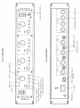
T L Audio
IVORY SERIES
User Manual
PA-5001
VALVE PRE-AMPLIFIER
Tony Larking Professional Sales Limited,
interstage
Phistersvej 31, 2900 Hellerup, Danmark
Telefon 3946 0000, fax 3946 0040
www.interstage.dk
- pro audio with a smile
Letchworth, England.
INTRODUCTION
The T L Audio Ivory Series consists of a range of hybrid valve signal processors, which utilise low
noise solid state electronics in conjunction with classic valve circuitry to produce audio processing
units offering very high quality signal paths with the unique valve audio character. The Ivory Series
units offer comprehensive control facilities, whilst remaining straight-forward to operate, and
represent excellent value for money.
The PA-5001 is a four channel valve microphone pre-amplifier. Featuring very low noise and an
exceptionally wide bandwidth, it provides continuously variable input and output gain controls, high
pass filter and phase reverse switches, and independently switched +48V phantom power.
The block diagram of one channel of the unit is shown in fig.1. The microphone input socket is a
balanced XLR connector, with phantom power applied via a front panel switch. The gain of the
input stages is controlled by a continuously variable rotary control providing between 16 and 60dB
of gain. A switchable 12dB per octave high pass filter is provided to reduce unwanted background
low frequency noise, such as traffic rumble or wind effects.
The second stage of the pre-amplifier consists of both sections of a twin triode valve (vacuum tube),
which has a variable signal level depending on the setting of the input gain control. Thus the
characteristic valve sound may be subtly introduced or used to effect by turning up the input gain. A
variable intensity “DRIVE” LED monitors the input to the triode circuit to indicate the degree of
valve “warming” that is being introduced. A second, “PEAK”, LED operates as a conventional
headroom warning indicator.
Phase reverse may be applied, prior to the output level control which allows matching to the
sensitivity of the following equipment (e.g. mixing console or tape machine). The combination of
input and output gain controls allows optimisation of the operating level in the valve stages, to
produce a clean uncoloured sound through to a signal with a degree of valve warmth added.
Each channel has a balanced line level output on an XLR socket at a nominal level of +4dBu, and an
unbalanced output on a jack socket at a nominal level of -10dBu.
Please read this manual fully before installing or operating the Pre-Amplifier.
PRECAUTIONS
The T L Audio PA-5001 Pre-Amplifier requires very little installation, but like all electrical
equipment, care must be taken to ensure reliable, safe operation. The following points should always
be observed:
- All mains wiring should be installed and checked by a qualified
electrician,
- Ensure the correct operating voltage is selected on the rear panel
before connecting to the mains supply,
- Never operate the unit with any cover removed,
- Do not expose to rain or moisture, as this may present an electric
shock hazard,
- Replace the fuse with the correct type and rating only.
Warning: This equipment must be earthed.
INSTALLATION
AC Mains Supply.
The unit is fitted with an internationally approved 3 pin IEC connector. A mating socket with power
cord is provided with the unit, wired as follows:
Brown: Live.
Blue:
Neutral.
Green/Yellow: Earth (Ground).
All mains wiring should be performed by a qualified electrician with all power switched off, and the
earth connection must be used.
Before connecting the unit to the supply, check that the voltage selector switch on the rear panel is
correctly set. The unit may be set for 115V (accepting voltages in the range 110V to 120V, 60Hz
AC), or to 230V (for voltages in the range 220V to 240V, 50Hz AC). Adjustment to the operating
voltage should be made by sliding the selector switch left or right with a small screwdriver until the
desired voltage is displayed. The mains fuse required is 20mm anti-surge, 1AT rated at 250V. If it
ever necessary to replace the fuse, only the same type and rating must be used. The power
consumption of the equipment is 30VA.
Warning:
attempted operation on the wrong voltage setting, or with an
incorrect fuse, will invalidate the warranty.
Audio Operating Level.
The pre-amplifier is equipped with outputs suitable for connection to a wide variety of other audio
equipment. Generally, the balanced XLR connections will be required for interfacing to other
professional equipment, where the operating level (line-up level or nominal level) will be +4dBu, or
about 1.2V rms. The unbalanced jack connectors are generally intended for interfacing to semiprofessional equipment and have an operating level of -10dBu, or about 225mV rms.
Both outputs of each channel may be used simultaneously if required. Balanced interconnection is
always preferable to obtain the best headroom and noise rejection, but can only be used if the other
equipment in the chain, e.g. the mixing console, also has provision for balanced connections.
Microphone Inputs.
Each channel has a female, 3 pin XLR connector, suitable for balanced low impedance (150 to 600
ohm) microphones. The mating connector should be wired as follows:
- Pin 1 = Ground (screen).
- Pin 2 = Signal Phase (also known as “+” or “hot”).
- Pin 3 = Signal Non-Phase (“-” or “cold”).
Balanced Outputs.
The output is via a balanced, 3 pin male XLR connector. The mating connector should be wired as
follows:
- Pin 1 = Ground (screen),
- Pin 2 = Signal Phase (“+” or “hot”),
- Pin 3 = Signal Non-Phase (“-” or “cold”).
Unbalanced Outputs.
An unbalanced line output is provided for each channel, on a 0.25” mono jack socket.
- Tip =
Signal Phase (“+” or “hot”).
- Screen = Ground.
Ventilation.
The unit generates a small amount of heat internally. This heat should be allowed to dissipate by
convection through the grills in the side panels and front panel, which must not be obstructed. Do
not locate the unit where it will be subject to external heating, for example in the hot air flow from a
power amplifier, or on a radiator. If used free standing, ensure that the equipment is protected
against rain and spillage of liquid.
The pre-amplifier may be free standing, or mounted in a standard 19” rack.
Rear Panel.
The rear panel connectors are identified in fig.3. Make sure that all settings, mains and audio
connections have been made as described above before attempting to operate the equipment.
OPERATION.
Front Panel.
The front panel controls are identified in fig.2. Each of the four sections is identical.
Phantom Power.
Phantom power may be applied to the microphone socket by depressing the +48V switch. Do not
attempt to connect any microphone that does not require phantom power, or any other equipment
such as a DI box, to an input socket that has phantom power switched on.
CAUTION: Never switch phantom power on or off, or plug /
unplug a microphone with phantom power applied
unless the output level control is turned down.
Failure to do so may result in a thump in your
monitor loudspeakers or PA system.
Input Gain.
The gain of the input stage is variable from +16 to +60dB. This is a very wide range, to cater for all
types of microphone and recording situations, but care must be taken not to apply large, sudden
changes in gain which may result in unexpectedly large output signals.
Generally, it is advisable to set the input gain such that the peak LED just begins to illuminate on the
loudest expected signal. This ensures that the optimum signal to noise ratio is obtained, whilst
allowing a good margin of headroom.
DRIVE and PEAK LEDs.
The orange Drive LED provides a visual indication of the signal level through the valve stages, and
therefore the extent of “warming” or valve character being introduced. The drive LED will gradually
illuminate as the input level or gain is increased, over the range 0dB to +12dB.
The red Peak LED operates as a conventional warning that clipping is about to occur. The operating
level of the entire signal chain is monitored, and the LED illuminates when there is less than 5dB of
headroom remaining.
If the output gain controls is set to its centre, 0dB, position the Peak LED will illuminate some 8dB
after the Drive LED has reached its full intensity. However, it is possible to add gain further down
the chain (the output level control provides up to 15dB of gain), which will cause the Peak LED to
illuminate at a lower level of Drive. This situation implies that a high level of “clean” signal is
present, without driving the valves at a high level.
90Hz Filter.
The high pass filter switch restricts the low frequency response of the pre-amplifier, to effectively
remove rumble or LF noise from the signal. The filter is a second order, 12dB per octave design,
with a -3dB point at 90Hz, which has been developed to remove unwanted noise and improve
intelligibility without affecting vocal or bass instrument programme content.
Phase Reverse.
The phase reverse switch allows correction of a phase error, which may have occurred in
microphone wiring or placement. A phase mis-match will probably manifest itself as an apparent
loss of bass content when two microphone signals are mixed together or fed to a stereo pair of
loudspeakers. If an error is suspected, it is a simple operation to check by phase reversing each
channel in turn.
Output Level.
The output level control acts a continuously variable fader on the output of the channel.
The centre point of the level control is the 0dB setting, with up to 15dB of additional gain available.
The output of the pre-amplifier is capable of +26dBu, which is sufficient to directly interface and
fully modulate a digital multitrack for direct to tape recording. This technique is gaining in
popularity as a means of recording a very high quality signal prior to mixdown, avoiding the noise
and colouration added by recording through a mixing console.
In other applications, such as feeding into a console or signal processor, a much lower output level
will be required. The output level control allows precise control and fading of the signal without
affecting the operating level - and therefore signal quality - in the pre-amplifier.
SPECIFICATIONS
Microphone Input:
Electronically balanced.
Input impedance greater than 2Kohm.
Gain range +16dB to +60dB.
Noise -127dBu (EIN with 150 ohm source, 22Hz - 22KHz and
maximum gain).
3 pin female XLR connector.
Phantom Power:
+48V at 10mA maximum per microphone.
High Pass Filter:
-3dB at 90Hz, 12dB per octave.
Balanced Outputs:
Electronically balanced, unbalanced compatible.
Output impedance 47 ohms.
Maximum level +26dBu.
3 pin male XLR connector.
Unbalanced Outputs:
Output impedance 47 ohms.
Maximum level +18dBu into 10Kohms.
2 pole 0.25” jack socket.
Frequency Response:
10Hz to 40KHz, +0, -1dB.
Dimensions:
19” rack mounting, 2U high.
483mm wide x 88mm high x 200mm deep.
Power Requirements:
Rear panel selectable for 220-240V 50Hz or 110-120V 60Hz
operation.
Rear panel fuse 20mm, 1AT, 250V.
Power consumption 20VA typical.
Detachable 3 pin IEC connector, mating connector and cable
supplied.
Front panel On/Off switch with green LED.
Weight:
2.5Kg.
The above specifications are subject to change without notice.
SERVICE
Should the pre-amplifier require service, it must be taken or posted to an authorised dealer. Please
retain the original packing for possible future use, and ensure the unit is suitably protected during
transit. The manufacturer cannot accept responsibility for damage caused during transportation.
The pre-amplifier is supported by a limited warranty for a period of one year from the date of
purchase. During this period, any faults due to defective materials or workmanship will be repaired
free of charge. The warranty excludes damage caused by deliberate or accidental misuse, operation
on the incorrect mains voltage, or without the correct type and value of fuse fitted. It is the user’s
responsibility to ensure fitness for purpose in any particular application. The warranty is limited to
the original purchase price of the equipment, and excludes any consequential damage or loss. If
claiming repair under warranty, please enclose proof of purchase date.
Please record the following details:
Serial Number.............................
Date purchased...........................
Dealer.........................................
interstage
Phistersvej 31, 2900 Hellerup, Danmark
Telefon 3946 0000, fax 3946 0040
www.interstage.dk
- pro audio with a smile