1
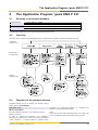
gesis®KNX P CO Presence detector (Art.-Nr. 83.020.1400.0) User Manual Operating instructions Dok.-Nr. BA000633 Stand: 10/2011 (Rev. A) Contents Wieland Electric | BA000633 | 10/2011 (Rev. A) 2 Contents Contents 1 1.1 1.2 1.3 Functional characteristics................................................................................. 4 Settings ........................................................................................................................4 Characteristics..............................................................................................................4 Technical Data..............................................................................................................4 2 2.1 2.2 2.3 2.4 2.4.1 2.4.2 2.4.3 2.4.4 2.4.5 2.4.6 2.5 2.5.1 2.6 The Application Program ‘gesis KNX P CO’...................................................... 5 Selection in the product database ...............................................................................5 Overview ......................................................................................................................5 Functions of the presence detector .............................................................................5 Parameters ...................................................................................................................6 Settings ........................................................................................................................6 Outputs light A, B.........................................................................................................6 Output presence...........................................................................................................7 Output surveillance ......................................................................................................8 Output brightness ........................................................................................................8 Remote/Scenes ............................................................................................................8 Communication objects ...............................................................................................9 Object characteristics...................................................................................................9 Description of the communication objects................................................................10 3 3.1 3.1.1 3.1.2 Configuration of the actuators........................................................................ 12 Recommended configuration ....................................................................................12 Actuators without a separate object for status acknowledgement (value) ...............12 Actuators with a separate object for status acknowledgement (value) ....................12 4 4.1 4.2 4.3 Important information .................................................................................... 13 Parallel circuit operation.............................................................................................13 Normal or test operation ............................................................................................13 Push buttons ..............................................................................................................13 5 5.1 5.1.1 5.1.2 5.1.3 5.1.4 Application Example ....................................................................................... 14 Single room with two switched light groups.............................................................14 Necessary equipment ................................................................................................14 Realization ..................................................................................................................14 Important parameter settings ....................................................................................14 Assignment of objects ...............................................................................................15 Wieland Electric | BA000633 | 10/2011 (Rev. A) 3 Functional characteristics 1 Functional characteristics The switching behaviour of the presence detector is controlled by presence and light control operating modes. In the ‘Switching’ operation mode, the lightning switches on with darkness and presence and off with sufficient light or absence. In the ‘constant light control’ operating mode the sensor controls the artificial light daylight-dependent on a constant lighting level. It is possible to use the presence detector in fully automatic or semi automatic mode. In ‘Fully automatic’ mode the light switches on and off automatically according to presence and light. In ‘Semi-automatic’ mode the light must be switched on manually and switched off automatically. The presence detector has a mixed light measurement and is suiable for controlling fluorescent lamps (FL/PL), halogen and glow lamps. With the object presence it is also posible to send a telegram for HVAC control. The switching behaviour is only controlled by presence. Several detectors can be connected with each other (Master/Slave) to increase the detection area. The master controls lightning and HVAC. All other detectors merely provide presence information as slaves. Also it is possible to connect several detectors as master with each other (Master/Master). Every master controls its lighting group according to its own light measurements. Presence is detected by all the detectors. Master or 1.3 slave operating is selected via configuration. In the test operation mode it is possible to check the detection range and the configuration. 1.1 Settings All settings are adjusted using ETS. ETS2 V1.2 or newer is requred. 1.2 Characteristics The presence detector detects persons present as a result of the slightest movements. At the same time its light sensor measures the brightness level in the room and compares it to the preset brightness value. • • • • • • • • • Option of one or two outputs for light Switching or constant light control Output presence for control of HVAC Output surveillance with cyclical detector points Output brightness with cyclical output of brightness value in lux Parallel circuit operation master-slave, master-master for uninterrupted coverage of large areas Separate disabling function for light and presence Scene control with two scenes per lighting group User remote control clic (optional) Technical Data Voltage Supply Bus voltage Permitted working temperature Protection rating Recommended installation height Max. Range 0 °C bis +50 °C EN 60529: IP 40 2.0 – 3.0 m 6 × 6 m at a height of 2.5 m 8 × 8 m at a height of 3.5 m 360° horizontal, 120° vertical Sitting Person Person in action e.g. walking (presence detector) (movement detector) 3.0 × 3.0 m 4.5 × 4.5 m ± 0.5 m 4.0 × 4.0 m 6.0 × 6.0 m ± 0.5 m 4.5 × 4.5 m 7.0 × 7.0 m ± 1 m – 8.0 × 8.0 m ± 1 m Approx. 10–1500 Lux, can be deactivated 30 sec to 120 min 0 sec to 60 min 30 sec to 120 min 0 sec to 30 min 70 × 70 mm ∅ 55 mm (NIS, PMI) 102.5 × 102.5 × 33 mm (W × D × H) Detection range Detection area at height 2.0 m 2.5 m 3.0 m 3.5 m Mixed light measurement Light run-on time Light stand-by time Presence run-on time Presence switch on delay Assembly plate Size of flush-mounted socket Dimmensions Wieland Electric | BA000633 | 10/2011 (Rev. A) 4 The Application Program ‘gesis KNX P CO’ 2 The Application Program ‘gesis KNX P CO’ 2.1 Selection in the product database Manufacturer Product family Wieland Electric GmbH Physical sensor Product type Program name Presence detector gesis KNX P CO Download the application from: http://www.wieland-electric.com/ 2.2 Overview Structure of the compact office EIB application at the functions (outputs), parameter and object levels Functions (section 2.3) Parameters (section 2.4) Objects (section 2.5) 2.3 Functions of the presence detector Possible settings are set in oblique, the default setting being shown in bold oblique. Operation mode Master stand-alone Presence detector operates as an autonomous unit. Master in parallel In order to expand the detection area, additional detectors are connected as slaves to a master in parallel circuit operation, or several masters in parallel circuit Wieland Electric | BA000633 | 10/2011 (Rev. A) operation are connected together as required (see Chapter 4, ‘Important information’). Slave slaves are used to expand the detection area. Their sole role is to supply presence information to the master. 5 The Application Program ‘gesis KNX P CO’ NOTICE Please also read the information on cycle time for parallel circuit operation in Section 4.1 2.4.1 Settings Name Value Meaning Device type gesis KNX P CO fixed setting Outputs light (Section 3.3.1) 2.4.2 Outputs light A, B Output light A active presence detector switches or controls one lighting Switching or constant light control group in accordance with the presence of persons and Switching (on/off) natural daylight. On detection of movement and inadequate brightness the output light sends an ON telegram. At the end of the Outputs light A,B active The presence detector switches or controls two lighting switch-off delay time or in the case of adequate groups in accordance with the presence of persons and brightness, an OFF telegram is sent. natural daylight. A desired brightness value is defined Constant light control for this purpose, the second lighting group is switched On detection of movement and inadequate brightness in or controlled with a difference in brightness. the output light controls the lighting to the predetermined desired brightness level and keeps it Inactive The presence detector is not used for controlling constant during fluctuations in daylight. At the end of the switch-off delay time, or in case of adequate lighting. brightness when the lighting has already been dimmed Output presence (Section 3.3.2) to the minimum level, the lighting is switched off. A second output for light can also be controlled with a Output presence active Detector switches HVAC applications in accordance different brightness. with the presence of persons or supplies presence information to superordinate systems. (irrespective of brightness). NOTICE If two outputs for light A, B are active, both outputs will be in control or switching mode. A combination of control and switching mode is not possible. Inactive The presence detector is not used to control HVAC Fully or semi-automatic applications. fully automatic In “Fully automatic” operation mode, the output light Output surveillance active switches or controls the lighting automatically according The presence detector supplies a presence signal with to presence and ambient brightness. Switch off occurs reduced sensitivity for room surveillance. automatically. Output Surveillance (Section 3.3.3) Inactive The presence detector is not used for room surveillance. Output brightness (Section 3.3.4) semi-automatic In “Semi-automatic” operation mode, the lighting must always be switched on manually by push button or remote control. Switch off occurs automatically. Output brightness active Presence detector sends the measured room brightness (ignoring the reflection factor). NOTICE Lighting can be switched on manually, at any time, in both operating modes even with adequate daylight. Inactive The lights stay on for at least 30 minutes if people are The presence detector is not used as a brightness present in the room. After that, the sensor checks the sensor. light requirement based on the brightness level and turns off the light if there is sufficient brightness. The Normal or test operation light goes off after a preset run-on time if the room is Normal operation vacated. (See section 4.3, ‘Push buttons’). The detector must be in normal mode for regular • Switching (on/off): The sensor switches the lighting operation. on. • Constant light control: The sensor controls according Test mode to the set brightness level. The detector may be set to test mode for the purpose of checking the detection area and the linking of objects. Brightness value The switch-off delay times are reduced to 10 sec. The detector switches irrespective of daylight. The detector The brightness value can be set between 1.0 and 8.0. The factory default value is 4.0, which corresponds to a restarts when switched to normal. brightness of approx. 400 lux, depending on the reflective properties of the room. (Guide values, 2.4 Parameters dependent on the room: 2~100 lux, 3~200 lux, 4~400 Parameters are set in oblique, the default setting is lux, 5~800 lux, 6~1600 lux). In switching mode, the brightness value can be deactivated by means of the shown in bold oblique. Wieland Electric | BA000633 | 10/2011 (Rev. A) 6 The Application Program ‘gesis KNX P CO’ The output for presence is unaffected by the setting “none, solely dependent on presence”. The service remote control QuickSet aids in setting the disablement of the outputs for light. It has its own brightness value, taking into account the reflection disabling function. The outputs for surveillance and factor (see detector operating manual). brightness are unaffected by the disablement of the outputs for light. Brightness difference Brightness value changeover (This setting is only possible if two lighting groups are active) When brightness value changeover is activated, it is possible to switch between two desired brightness The brightness difference adjusts the different light values by means of a telegram in the current mode. An requirement of lighting group B in comparison to ON telegram to the object concerned switches to the lighting group A: alternative desired brightness value, an OFF telegram • A positive value indicates a lower daylight level in the switches back to the original value. This applies both to switching and to constant light control. In this way it is area of lighting group B (more artificial light needed). • Synchronous indicates that both lighting groups are possible to realise day and night modes with two different levels of brightness, for example. being switched or controlled uniformly. • A negative value indicates a higher daylight level in Behaviour at the start of control the area of lighting group B (less artificial light needed). (Only with activated constant light control ) Example: Two lighting groups are installed in an office with good natural light. Lighting group A is close to the windows, lighting group B is in the interior of the room. Sensible settings are +20% or +40%. Switch-off delay time Depending on the configuration of the switching/ dimming actuator, the constant light control can be started with a value telegram or an ON telegram. Normally it is started with a value telegram, the lighting dims to the desired brightness value in the time set in the actuator. The switch-off delay time can be set between 30 sec. and 20 min. It adapts itself to user behaviour. It can increase itself automatically to a max. of 15 min. or reduce itself to the pre-set minimum time. If set to less than 2 min. or more than 15 min. the switch-off delay time does not change in a self-adaptive manner. The switch-off delay time applies equally to both outputs for light. If the control is started with an ON telegram, the actuator jumps (dims) to its predefined switch-on value and begins controlling from this value. Stand-by time The switching behaviour is only affected by presence. The output for presence functions irrespective of daylight. In the case of presence, either an ON or OFF telegram or no telegram is sent. At the end of the switch-off delay time, either an ON or OFF telegram or no telegram is sent. (This setting is only possible if constant light control is active) In control mode, an activated stand-by time results in both lighting groups being dimmed to a minimum value at the end of the switch-off delay time. The stand-by time can be set between 0 sec. and 60 min. With Stand-by ON, the lighting remains continuously on stand-by. If the room brightness rises above the desired value, the lighting switches off. If the room brightness falls below the desired value, the lighting switches automatically to stand-by, even if no one is present. In this way a minimum level of lighting is guaranteed even during the hours of darkness. Disabling outputs for light The two outputs for light are both disabled with either an ON or an OFF telegram. At the start of the period of disablement the outputs for light can send one of the following final telegrams as desired: ON, OFF, or no telegram. All telegrams are suppressed for the duration of the disablement. The outputs for light are re-enabled by means of an ON or OFF telegram, complementary to the telegram at the time of disablement. When the period of disablement is cancelled the detector sends the current status or continues the constant light control. Wieland Electric | BA000633 | 10/2011 (Rev. A) NOTICE Please read chapter 3, ‘Configuration of the actuators’. 2.4.3 Output presence Switch-off delay time 30 s … 15 min … 120 min The switch-off delay time for presence is restarted after every movement. Switch-on delay time inactive Switch-on delay time is 0 s. 30 s to 30 min The switch on delay time for presence can be set between 0 s and 30 min. Disabling the output for presence Send ‘ON’ telegram Send ‘OFF’ telegram Send no telegram The output for presence can be disabled with either an ON or OFF telegram. At the start of the period of disablement the output for presence can send one of the following final telegrams as desired: ON, OFF, or no 7 The Application Program ‘gesis KNX P CO’ telegram. All telegrams are suppressed for the duration NOTICE of the disablement. The output for presence is reThe lux value provided by the output for brightness is enabled by means of an ON or OFF telegram, complementary to the telegram at the time of disablement. not suitable for an external control. The constant light When the period of disablement is cancelled the control from the outputs for light should be used for this purpose. detector sends the current status. The outputs for light, surveillance and brightness are Remote/Scenes unaffected by the disablement of the output for 2.4.6 presence. Scenes 2.4.4 Output surveillance Internal scenes The switching behaviour is only affected by presence The value to which each lighting group will dim on and reliably detects the presence of persons. The output choice of scene 1 or scene 2 can be determined separately. for surveillance functions irrespective of daylight. In addition, the scenes can be called up by means of Report type the user remote control clic (optional). The scenes can be saved via the ETS or with the clic. Cyclic with confirmation On detecting movement, the output for surveillance External scenes sends an ON telegram. If it receives no confirmation, it It is possible to control an external scene component in repeats the ON telegram at regular intervals. (Waiting place of the internal scene component. The remote time for acknowledgement). control clic (optional) is required for this purpose. Pressing on scene button 1 on the clic sends an OFF Switching (on/off) telegram, pressing on scene button 2 sends an ON On detecting movement, the output for surveillance telegram. sends an ON telegram; at the end of the switch-off delay time for surveillance, an OFF telegram. The OFF Save scenes with telegram can optionally be suppressed. ETS Behaviour on return of bus voltage With ETS the user can specify the dimming values for scene 1 and scene 2, respecitvely. Output for surveillance disabled Output for surveillance enabled Remote control The behaviour on return of bus voltage defines whether Light scenes are set via button or remote control the output for surveillance is to be enabled or disabled (optional), and stored by pressing the button longer. during a restart following a loss of bus voltage. Output value scene 1, lighting group A/B Sabotage, cyclical OFF 30 s … 30 min The scene 1 output value does not affect the respective The cyclical detection point sends OFF telegrams at channel. regular intervals in order to indicate unauthorised ON removal of the detector or a bus interruption. The lighting group will be dimmed to the preset lighting value upon transmitting the information for scene 1. NOTICE Trigger telegrams from the master-slave parallel circuit Output value scene 2, lighting group A/B operation do not trigger the output for surveillance. OFF The scene 2 output value does not affect the respective 2.4.5 Output brightness channel. 30 s to 30 min ON 0 % to 50 % The lighting group will be dimmed to the preset lighting The brightness value object gives the room brightness value upon transmitting the information for scene 2. (measured value without taking a reflection factor into account) as a 2-byte value in lux in accordance with User remote control clic (optional) EIS5. The maximum time interval between two telegrams Switching/dimming internal can be set between 30 s and 30 min. The minimum time Pressing longer on the left-hand row of / buttons on the clic switches the output for light A on or off. Briefly interval is 15 s. The minimum brightness change before a telegram is button pressure dims the lighting while the button is depressed. If both outputs for light A,B are active, the sent can be set between 10 % and 90 %. right-hand row of / buttons controls output for light B in like manner. Switching/dimming external Pressing briefly on the relevant row of / buttons Switching/dimming ext. on the clic switches an external Wieland Electric | BA000633 | 10/2011 (Rev. A) 8 The Application Program ‘gesis KNX P CO’ consumer on or off (channel 1 or 2). Longer button Group address remote control clic pressure dims the external consumer while the button is A+B depressed. A Sun blind external B Pressing briefly on the relevant row of / buttons of C+D the clic raises or lowers a sunblind. Longer button C D pressure opens or closes the slats. E No function The choice of group address (position of the channel selector switch on the remote control clic) allows adjacent detectors that are controlled with the user remote control clic to be separated from one another. For further information, please also see the operating manual for the user remote control clic. 2.5 Communication objects 2.5.1 Object characteristics The presence detector has 27 communication objects. Table 1: Communication flags Flag Name C R W T Communication Read Write Transmit Table 2: Objects and flags Nr. Object name Function Type 0 1 2 3 4 5 6 7 8 9 10 11 12 13 14 15 16 17 18 19 20 21 22 23 24 Output light A Output light A Output light A Output light A Output light B Output light B Output light B Output light B Outputs light A, B Output presence Output presence Parallel circuit operation Input / output scene IR extern channel 1 IR extern channel 1 IR extern channel 2 IR extern channel 2 IR extern channel 1 IR extern channel 1 IR extern channel 2 IR extern channel 2 Output surveillance Output surveillance Output surveillance Output surveillance Switching Brighter / darker Set value Status value Switching Brighter / darker Set value Status value Disable / enable Switching Disable / enable Trigger input / output Scene 1 / 2 switching Brighter / darker switching Brighter / darker Sunblind up / down Slats open / shut Sunblind up / down Slats open / shut Report Confirmation Sabotage cycl. Enable 1 Bit 4 Bit 1 Byte 1 Byte 1 Bit 4 Bit 1 Byte 1 Byte 1 Bit 1 Bit 1 Bit 1 Bit 1 Bit 1Bit 4 Bit 1Bit 4 Bit 1 Bit 1 Bit 1 Bit 1 Bit Wieland Electric | BA000633 | 10/2011 (Rev. A) C Flags R W T 9 The Application Program ‘gesis KNX P CO’ Nr. 25 26 Object name Function Output brightness Outputs light A, B Sending Lux value Brightness value changeover Number of communication flags Number of group addresses Number of allocations 2.6 Type 1 Bit C Flags R W T 27 90 90 Description of the communication objects Object 0, ‘Output light A’: Switching On detection of movement and inadequate brightness each output light sends an ON telegram. At the end of the switch-off delay time or in case of adequate brightness, an OFF telegram is sent. Object 1, ‘Output light A‘: Brighter / darker On detection of movement and inadequate brightness each output light begins to send value telegrams (control begins with a value telegram) or an ON telegram (control begins with an ON telegram). At the end of the switch-off-delay time or in case of adequate brightness an off telegram is sent. telegramat time of disablement. On re-enabling, the detector sends its current status. Object 11, ‘Parallel circuit operation’: Trigger input / output (Master in parallel circuit operation or slave only) The trigger input / output is required for parallel circuit operation of multiple presence detcors. Each detector send a maximum of two ON telegrams a minute as trigger signals which are evaluated by the masters. The interval between two telegrams can be set to a maximum of four minutes. NOTICE Object 2, ‘Output Light A’: Set value On detection of movement and inadequate brightness The interval between two trigger telegrams must each output light begins to send value telegrams always be set to a smaller value than the switchoff (control begins with a value telegram). The lightning delay times! start with a defined value for the brightness. At the end of the switch-off-delay time or in case of adequate Object 12, ‘Input / output scene’: Scene 1 / 2 Internal scene: brightness, an OFF telegram is sent Object 3, ‘Output light A’: Status value The presence detector sends the status value cyclically. An OFF telegram to the scene output object calls up scene 1, an ON telegram calls up scene 2. Object Object Object Object Control of the scene component: 4, 5, 6, 7, ‘Output ‘Output ‘Output ‘Output light light light light B‘: B‘: B’: B’: Explanations of objects objects 4–7 for output ‘B’. Switching Brighter / darker Set value Status value 1–6 apply identically Pressing scene button 1 on the user remote control clic send an OFF telegram to the scene output object, pressing scene button 2 sends an ON telegram to Object 13, ‘IR ext. channel 1’: switching Object 14, ‘IR ext. channel 1’: brighter / darker Object 8, ‘Enable outputs light A, B: Disable / Enable Object 15, ‘IR ext. channel 2’: switching The two outputs for light are both disabled with an ON Object 16, ‘IR ext. channel 2’: brighter / darker or OFF telegram. At the start of the period of disableSwitching / dimming external: ment, the outputs for light are re-enabeled by means of an ON or OFF telegram, complementary to the telegram Pressing the /buttons briefly causes an ON or OFF at the time of disablement. When the period of telegram to be sent via the object ‘switching’. Sustained disablement is cancelled the detector always sends the pressure on the button calls for the light intensity to current status or continues the constant light control. be increased releasing the button stops this process. Sustained pressure on the button calls for the light Object 9, ‘Output Presence‘: Switching intensity to be decreased releasing the button stops this In the case of presence, the output for presence sends process. Channels 1 and 2 of the remote control must an ON or OFF telegram or no telegram (independent of each be set separately. daylight). At the end of the switch-off delay time, an ON or OFF telegram, or no telegram is sent. The optinal user remote control clic is required for this procedure. Object 10, ‘Output Presence’: Disable / Enable The output for presence is disabled by means of an ON or OFF telegram. At the start of the period of disablement, the output for presence can optionally send one of the following final telegrams: ON, OFF, or no telegram. The output presence is re-enabled by means of an ON or OFF telegram, cmplementary to the Wieland Electric | BA000633 | 10/2011 (Rev. A) 10 The Application Program ‘gesis KNX P CO’ Object Object Object Object 17, 18, 19, 20, ‘IR ‘IR ‘IR ‘IR ext. ext. ext. ext. channel 1’: channel 1’: channel 2’: channel 2’: sunblind up / down slats open / shut sunblind up / down slats open / shut Sunblind external: Pressing the / buttons briefly causes an ON or OFF telegram to be sent via the object ‘slats open / shut’. Sustained presure on the / buttons causes an ON or OFF telegram to be sent via the object ‘sunblind up/down’. Channels 1 and 2 of the remote control must each be set separately. The optinal user remote control clic is required for this procedure. Object 21, ‘Output surveillance’: report Object 22, ‘Output surveillance’: confirmation Cyclical with confirmation: On detecting movement, the output for surveillance sends an ON telegram. If the detector receives no acknowledgement to the telegram within the predefined waiting time, it repeats the ON telegram. This process is repeated until an ON or OFF telegram is received at the object confirmation. Switching (on/off): On detecting movement, the output for surveillance sends an ON telegram. And at the end of the switch-off delay time for surveillance an OFF telegram. Object 23, ‘Output surveillance’: Sabotage cycl. In order to identify removal of the detector, the object ‘sabotage cyclical’ sends OFF telegrams at regular intervals whenever the detector is in operation. Object 24, ‘Output surveillance’: Enable In both detection types the output for surveillance can be enabled or disabled during operation with an ON telegram or an OFF telegram respectively. Object 25, ‘Output brightness’: sending lux value The output for brightness sends the current brightness value in the form of an EIS5 telegram without allowance for a reflection factor. The telegram frequency depends on the maximum cycle time and the minimum brightness change Object 26, ‘Output lights A, B’: Brightness value changeover An ON telegram switches to the alternative brightness value an OFF telegram uses the orginal brightness value as desired value. Wieland Electric | BA000633 | 10/2011 (Rev. A) 11 Configuration of the actuators 3 Configuration of the actuators 3.1 Recommended configuration Duration for the dimming process 0 – 100 % Immediate or progressive dimming 3.1.2 10 seconds Actuators with a separate object for status acknowledgement (value) Group address dimming actuator Progressive Parameter R C 6 ON / OFF 10 / 0 / 1 x x Default x Default x Default Adopt dimming values immediately Immediately Switching off by dimming possible No 9 Dimming 10 / 0 / 2 x Switching on by dimming possible Yes 12 Set value 10 / 0 / 3 x x 18 Status (value) 10 / 0 / 7 x x Lower dimming limit Minimum (0 %) Upper dimming limit Maximum (100 %) Switch-off behaviour (switch off or dim to off) Brightness level at switch on (optional) Send status value of dimming value Switch off Only by means of reading request NOTICE The parameter designations may differ according to the dimming actuator or switching/dimming actuator model. It is unnecessary for automatic status messages to be generated by the actuator. The detector collects this information itself. 3.1.1 T Default Group address presence detector Parameter 50 % Flag W Group address Group address 0 ON / OFF 10 / 0 / 1 1 Brighter / Darker 10 / 0 / 2 2 Set value 10 / 0 / 3 12 Status Value 10 / 0 / 7 NOTICE If several actuators are connected to a single detector light output, care should be taken to ensure identical parameterisation of the actuators. Exception: The status value object may only be linked with one of the actuators for each lighting group. Actuators without a separate object for status acknowledgement (value) Group address dimming actuator Parameter Group adress 6 ON / OFF 10 / 0 / 1 9 Dimming 10 / 0 / 2 12 Set value 10 / 0 / 7 C R x x 1) 10 / 0 / 3 x 2) x Flag W T x Default x Default x Default 1) set sending 2) with certain actuators, the read flag must be set manually Group address presence detector Parameter 0 ON / OFF Group adress 10 / 0 / 1 1 Brighter / Darker 10 / 0 / 2 2 Set value 10 / 0 / 3 12 Status Value 10 / 0 / 7 NOTICE If several actuators are connected to a single detector light output, care should be taken to ensure identical parameterisation of the actuators. Exception: The read flag may only be set for one of the actuators for each lighting group. Wieland Electric | BA000633 | 10/2011 (Rev. A) 12 Important information 4 Important information 4.1 Parallel circuit operation For larger rooms, multiple detectors can be connected in parallel. In this way their combined presence detection area is increased. One “master” can be connected in parallel with several “slaves”. This is accomplished by interconnecting the trigger inputs and outputs. The slaves only supply the presence information from their own detection area. Brightness measurement and management of all parameter settings is done by the master. Parallel connection of multiple masters is also possible. In this case the presence detection is done jointly whereas the light measurement, parameter settings and lighting control are individually processed by each master. This offers multiple outputs for light with individual brightness measurement but a common presence detection. The function of the outputs for presence, surveillance and brightness remain unaffected. NOTICE A discrete KNX push button with discrete group adress for every lighting channel has to be used for manual override of two lighting groups A, B. NOTICE In parallel circuit operation, each master in parallel circuit operation and each slave sends two telegrams per minute for as long as someone is present in the detection area. The interval between two telegrams can be extended up to four minutes. 4.2 Normal or test operation The test mode enables the presence detection function to be checked. It can be selected via the ETS or also using the service remote control QuickSet plus. When selected with the QuickSet plus, the test mode ends automatically after 10 min. Please refer to the notes concerning the test mode in the operating manual for the detector. 4.3 Push buttons The detector responds to telegrams sent directly to the actuators by push buttons or superordinate functions: Switching (On/Off): If the detector receives an ON telegram intended for the switching actuator, the lighting remains switched on for 30 minutes in the case of presence. At the end of the 30 minutes, the light measurement is reactivated. If the brightness is adequate, an OFF telegram is sent. Constant light control: If the detector receives an ON telegram intended for the actuator, the constant light control is active. If the detector receives a value or dimming telegram intended for the actuator, control is suspended for the duration of the presence. Once the room becomes unoccupied and the switch-off delay time has expired, the detector returns to control mode. In both cases: If the detector receives an OFF telegram intended for the actuator, it remains switched off for the duration of presence. Once the room becomes unoccupied and the switch-off delay time has expired, the detector returns to switching or control mode. Wieland Electric | BA000633 | 10/2011 (Rev. A) 13 Application Example 5 5.1 Application Example Single room with two switched light groups The presence detector gesis KNX P CO serves as standalone master. The master switches two light groups. Additionally, the light can be controlled manually via pushbuttons. For light control, gesis RM series components are used. The presence output provides the presence information for e.g. controlling air conditioning. Thus heating operations can be performed as efficient as possible. 5.1.2 Realization 5.1.3 Important parameter settings Parameters not mentioned here maintain their default or customized settings. 5.1.1 Name Type Order no. Presence detector gesis KNX P CO 83.020.1400.0 Sensor interface gesis KNX TA 2/2 83.020.1404.0 gesis RM series – devices for decentralized installation Power supply gesis EIB RM-PS 83.020.0421.0 Base module gesis EIB RM-BAS 83.020.0400.3 Output module gesis EIB RM-0/4 83.020.0403.0 Parameters gesis KNX TA 2/2 Parameter side Channel 1 Parameters gesis KNX P CO Parameter side General declarations Parameter Operation mode Outputs light Output presence Output surveillance Normal or test operation Wieland Electric | BA000633 | 10/2011 (Rev. A) Setting Master stand-alone Outputs light A,B active Output presence active Inactive Necessary equipment Channel 2 Parameter Function Reaction to rising edge Reaction to falling edge Function Reaction to rising edge Reaction to falling edge Setting Switch/pushbutton Toggle None Switch/pushbutton Toggle None Normal operation 14 Application Example Parameters gesis EIB RM-BAS Parameter side Module selection Module 1 output A Module 1 output B Module 1 output C 5.1.4 Parameter Module 1 Operation mode Relay operation Operation mode Relay operation Operation mode Relay operation Setting 4 binary outputs Normal Normal Normal Normal Normal Normal Assignment of objects Wieland Electric | BA000633 | 10/2011 (Rev. A) 15 Application Example Notes Wieland Electric | BA000633 | 10/2011 (Rev. A) 16 Application Example Wieland Electric | BA000633 | 10/2011 (Rev. A) 17 Application Example Wieland Electric | BA000633 | 10/2011 (Rev. A) 18 Wieland Electric | BA000633 | 10/2011 (Rev. A) 19