1
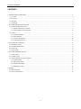
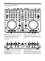
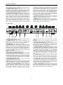
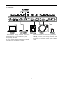
User Manual
PULSAR. User Manual
CONTENTS
1. CONTROLS AND CONNECTIONS .......................................................................................................................................................... 4
1.1. Top Panel.......................................................................................................................................................................................... 4
1.2. Front panel ........................................................................................................................................................................................ 4
1.3. Rear panel ........................................................................................................................................................................................ 5
1.4. Connections ...................................................................................................................................................................................... 6
2. SOFTWARE INSTALATION AND SETUP ............................................................................................................................................... 7
2.1. PULSAR Akiyama ASIO Drivers ....................................................................................................................................................... 7
2.1.1. Akiyama ASIO drivers’ installation ............................................................................................................................................ 7
2.1.2. Akiyama ASIO drivers Configuration ........................................................................................................................................ 8
2.2. Traktor 2............................................................................................................................................................................................ 8
2.2.1. Windows installation ................................................................................................................................................................. 8
2.2.2. MAC Installation ........................................................................................................................................................................ 9
2.2.3. Traktor 2 LE registration ......................................................................................................................................................... 11
2.2.4. Traktor 2 Setup Wizard ........................................................................................................................................................... 11
3. FUNCTIONS AND CONTROLS ............................................................................................................................................................. 13
3.1. Stand-alone controls ....................................................................................................................................................................... 13
3.2. Track/Sample Deck Mode............................................................................................................................................................... 13
3.3. Traktor 2 LE .................................................................................................................................................................................... 14
3.4. Traktor 2 PRO ................................................................................................................................................................................. 16
4. SETUP AND FIRMWARE UPDATE ....................................................................................................................................................... 19
4.1. Setting Software.............................................................................................................................................................................. 19
4.2. Firmware Update ............................................................................................................................................................................ 19
4.3. Changing Settings through the Controller ....................................................................................................................................... 19
4.3.1. Channel settings ..................................................................................................................................................................... 20
4.3.2. SHIFT button setting ............................................................................................................................................................... 20
4.3.3. Sample buttons setting ........................................................................................................................................................... 20
4.3.4. EQ Kill button setting .............................................................................................................................................................. 20
5. APENDIX ................................................................................................................................................................................................ 21
5.1. MIDI Specification ........................................................................................................................................................................... 21
5.2. Technical specifications .................................................................................................................................................................. 24
1
PULSAR. User Manual
Intended to alert the user to the presence of
important
operation
and
maintenance
(servicing) instructions in the literature
accompanying this appliance.
The lightning flash with arrowhead symbol
within the equilateral triangle is intended to
alert the use to the presence of un-insulated
“dangerous voltage” within the unit.
CAUTION: TO REDUCE THE RISK OF ELECTRIC SHOCK, DO NOT REMOVE ANY COVER. NO USER-SERVICEABLE PARTS
INSIDE. REFER SERVICING TO QUALIFIED SERVICE PERSONNEL ONLY.
WARNING: TO PREVENT FIRE OR SHOCK HAZARD. DO NOT USE THIS PLUG WITH AN EXTENSION CORD, RECEPTACLE OR
OTHER OUTLET UNLESS THE BLADES CAN BE FULLY INSERTED TO PRESENT BLADE TO PREVENT FIRE OR SHOCK
HAZARD. DO NOT EXPOSE THIS APPLIANCE TO RAIN OR MOISTURE. TO PRVENT ELECTRICAL SHOCK, MATCH WIDE BLADE
PLUG TO WIDE SLOT FULLY INSERT.
11. Ventilation Slots and openings in the cabinet are provided
for ventilation and to ensure reliable operation of the product
and to protect it from overheating, and these openings must
not be blocked or covered. The openings should never be
blocked by placing the product on a bed, sofa, rug, or other
similar surface. This product should not be placed in a built-in
installation such as a bookcase or rack unless proper
ventilation is the manufacturer's instructions have been
adhered to.
SAFETY INSTRUCTIONS AND GUARRANTY
INFORMATION
1. Read Instructions. All the safety and operating instructions
should be read before this product is operated.
2. Retain Instructions. The safety and operating instructions
should be retained for future reference.
3. Heed Warnings. All warnings on the appliance and in the
operating instructions should be adhered to.
12. Any mounting of the product should follow the
manufacturer's instructions, and should use a mounting
accessory recommended by the manufacturer. The
manufacturer will NOT take responsibility for nonrecommended accessories.
4. Follow Instructions. All operating and use instructions should
be followed; failure to do so can void this guarantee.
5. Water and Moisture. The appliance should not be used near
water - for example, near a bathtub, washbowl, kitchen sink,
laundry tub, in a wet basement, or near a swimming pool, and
the like.
13. Accessories. Do not place this product on an unstable cart,
stand, tripod, bracket, or table. The product may fall, causing
serious injury to a child or adult and serious damage to the
product. Use only with a cart, stand, tripod, bracket, or table
recommended by the manufacturer, or sold with the product.
6. Carts and Stands. The appliance should be
used only with a cart or stand that is
recommended by the manufacturer. An
appliance and cart combination should be
moved with care. Quick stops, excessive
force, and uneven surfaces may cause the appliance and cart
combination to overturn. Wall or Ceiling Mounting. The product
should be mounted to a wall or ceiling only as recommended
by the manufacturer.
14. Lightning. For added protection for this product during a
lightning storm, or when it is left unattended and unused for
long periods of time, unplug it from the wall outlet and
disconnect the antenna or cable system. This will prevent
damage to the product due to lightning and power-line surges.
15. Replacement Parts: When replacement parts are required,
be sure the service technician has used replacement parts
specified by the manufacturer or have the same characteristics
as the original part. Unauthorized substitutions may result in
fire, electric shock, or other hazards.
7. Heat. The appliance should be situated away from heat
sources such as radiators, heat registers, stoves, or other
appliances (including amplifiers) that produce heat.
16. Use only cables in accordance with present standards, ask
your dealer.
8. Object and Liquid Entry. Care should be taken so that
objects do not fall and liquids are not spilled into the enclosure
through openings.
17. Do not use right away the equipment in case has been
transported from a cold environment to a hot one. Moisture will
appear, let it off for a while.
9.
Damage Requiring Service. The appliance should be
serviced by qualified service personnel when:
18. Cleaning. Do not use cleaning sprays where the controls
are. The appliance should be cleaned only as recommended
by the manufacturer. Clean by wiping with a cloth slightly damp
with water. Avoid getting water inside the appliance.
A: The power-supply cord or the plug has been damaged; or
B: Objects have fallen, or liquid has been spilled into the
appliance; or
C: The appliance has been exposed to rain; or
D: The appliance does not appear to operate normally or
exhibits a marked change in performance; or
E: The appliance has been dropped, or the enclosure
19. Audio ON: When installation is complete and you are about
to start using the unit. Before switching ON the unit DO lower
the Mains and Headphones volume controls. Failure to do so
can result in hearing injuries or amplification stage damage.
damaged.
20. Safety Check Upon completion of any service or repairs to
this product, ask the service technician to perform safety
checks to determine that the product is in proper operating
condition.
10. Servicing. In accordance with E.U. directives the user shall
not attempt any service to the appliance beyond that described
in the operating instructions. All other servicing should be
referred to qualified service personnel. Failure to follow this
instruction can void this guarantee.
2
PULSAR. User Manual
21. For AC line powered units - Before returning repaired unit
to user, use an ohm-meter to measure from both AC plug
blades to all exposed metallic parts. The resistance should be
more than 100,000 ohms.
This product shall not be treated as
household waste. Instead it shall be handed
over to the applicable collection point for the
recycling of electrical and electronic
equipment. By ensuring this product is
disposed of correctly, you will help prevent
potential negative consequences for the
environment and human health, which could
otherwise be caused by inappropriate waste
handling of this product.
The recycling of materials will help to conserve natural
resources.
For more detailed information about recycling of this product,
please contact your local city office, your household waste
disposal service or the shop where you purchased the product.
22. To prevent fire or shock hazard. Do not use this plug with
an extension cord, receptacle or other outlet unless the blades
can be fully inserted to present blade, match wide blade plug
to wide slot fully insert.
TERMS OF USE
Your unit comes with a serial number sticked on it. Do not tear
the serial number; this can result in void guaranty.
SAFE AND EFICIENT USE
Select carefully the emplacement of the unit. Avoid placing it
under direct sun exposure. Avoid humid and damp places or
rough environments with excessive dust and vibrations and
excessive heat or cold. Also keep it away from humming
sources like the motors of whirl washers or transformers or
similar appliances.
No liquids must be close to the unit so that they can be spilled
on it. To completely disconnect the unit from you mains supply
unplug the plug of the adapter from the wall electric outlet.
The switch that controls the supply of electrical power to the
unit must be at easy reach in case is necessary a fast switch
off.
WARNING: do not place the unit in a closed environment
where is difficult to access the wall outlet.
Do not open the unit; it can cause personal injuries or the
damage of the equipment.
When unplugging the power supply cable of the adaptor from
the wall outlet, does not pull the cable. Take the plastic body of
the plug and unplug it.
Do not handle roughly the controls of the unit you can shorten
their lifespan.
Before moving the equipment, remember to unplug all cables.
Do not use chemical solvent to clean the unit. A dry and clean
cloth will do fine.
Safe this manual at reach so you can go back to the basic in
case you need it.
PRELIMINARY
Check the contents of the PULSAR box and find the following
items:
1- Controller
1- Installation and instructions CD
1- Quick Guide
1- Traktor LE CD
1- USB Cable (PC/MIDI)
FIRST STEPS
Caution on installation
Install the equipment on a stable and horizontal surface.
Avoid placing it under direct sun exposure humid and damp
places or rough environments.
Place the equipment as far away as possible of other audio
equipment as radios TVs etc.
3
PULSAR. User Manual
1. CONTROLS AND CONNECTIONS
1.1. Top Panel
1. Controls distribution for an optimal use of Virtual DJ and
Traktor 2.
2. Control of up to 4 Decks. MIDI notes are sent through
different MIDI channels upon selection; DECK A/B or C/D.
LEDs status are refreshed by firmware.
3. Touch-sensitive jog wheel with sensibility adjustment.
4. Durable large-size Cue, Play and Cue Play buttons.
5. Dual FX units control with 4 knobs and 4 buttons for each
unit.
6. Independent 8 samples buttons for sample.
7. Central mixer with 3 band equalizer with kill. On this section
also are controllable the functions; gain for each channel, fader
volume, crossfader, main output level and Traktor Loop
Recorder.
1.2. Front panel
1
2
3
4
5
1. MIC 1 Jack: This jack is used to connect a microphone to
the mixer. Connect your microphone via 1/4 inch jack. The
volume output level for microphone will be controlled by its
own respective volume knob.
2. MIC LEVEL Control: These rotary knob control the output
volume of MICROPHONE.
3. MIC ON/OFF Switch: Activate or deactivate the MIC input.
6
7
8
4. TOUCH SENSOR LEVEL Control: Adjust level of touch
sensitivity for the Jog Wheel.
NOTE: The touch sensitivity of the jog wheel can be adjusted
to fit the needs and feel of different users. When adjusting the
sensitivity, be conscious of extreme settings which may affect
your performance. Setting the sensitivity too high would
engage the touch sensitivity with the hand just above the
4
PULSAR. User Manual
wheel. Setting the sensitivity too low may not engage the touch
even while pressing firmly on the wheel.
5. X-FADER CURVE Switch: Allows adjusting the slope of
crossfader. Rotate clockwise to shorten fade time with sharper
cut off at either end. Rotate anti-clockwise to lengthen fade to
gradually mix across fader and 50/50 mix in center only.
6. MONITOR MIXING MODE Selector: This function allows
you to monitor the Cue level as well as the Master (main
output) level in your headphones. Channels Cue Level may
only be monitored if the channel CUE function is selected. To
select a channel cue function press the CUE BUTTON that is
directly associated with the specific channel you wish to
monitor. You may use the mixing function to blend both the
Cue level and the MASTER level together. You can vary the
output level to either hear more or less of either of the two
levels. Turning the Cue Mixing knob to the CUE position (left)
will allow you to hear more of the Cue level. Turning the knob
to the MASTER position (right) will allow you to hear more of
the Program level (main output). You may also use the Cue
Mixing Control to hear either the Cue level or the Master level
exclusively. If the knob is in the full CUE position you will only
hear the cue level, if the knob is in the full MASTER position
you will only hear the main output. This function is especially
useful when mixing without a monitor. Adjust the balance for
the CUE and master output to the headphone.
7. CUE LEVEL Control: This rotary knob is used to adjust the
headphone volume output level. Turn the knob in a clockwise
direction to increase the headphone volume.
8. PHONES Jacks: These jacks are used to connect your
headphones to the device allowing you to monitor the cue
channel. Always be sure the CUE LEVEL VOLUME is set to
minimum before you put the headphones on.
1.3. Rear panel
8
9
10 11 12
using line level input devices be sure the switch is in the “LINE”
position.
CAUTION: Always be sure main power is shut off before
change the position of the Line Level Selector Switch.
8. GND (GROUND TERMINAL): Be sure to connect turntable
ground leads to either or both of the two available ground
terminals. This will reduce the humming and popping noises
associated with magnetic phono cartridges.
9. CHANNEL PHONO/ LINE INPUT Connectors: Turntables
equipped with MM pickup cartridge (All DJ turntable use MM
pickup cartridges) may be connected to these jacks as long as
the PHONO/ LINE selector switches is in the “PHONE”
position. CD players, Tape Decks and other line level
instruments may only be connected to these jacks as long as
the PHONO/ LINE selector switches is in the “LINE” position.
Input volume will be controlled by the Channel gain control
knob.
10. PC/THRU Switch: Send the AUX or LN/PH 1 signals
directly to the master out and disconnects the computer output
or sent one of them to through the sound card. Select which
one, AUX or LN/PH1, from the Input 1 source selector switch.
11. AUX IN Jack: CD players, MP3 Player, Tablet Pad and
other line level instruments may only be connected to this jack.
Input volume will be controlled by the channel fader. The
channel Source Selector Switch must be in the "Aux" position,
to monitor any source connected to this jack.
12. INPUT 1/AUX GAIN knob: This knob is used to adjust the
audio source signal input gain for the channel 1. Never use the
gain control to adjust a channels output volume. Setting the
gain level properly will ensure a clean output signal.
1. POWER CORD Fastener: To fasten the power cord to
avoid unplugging the cord by accident.
2. POWER Connector: Plug in power adaptor here. DC
adaptor can be used when the USB port cannot provide
enough power to the unit. Please use only 6V DC adaptor.
3. POWER Switch: Turn this unit power ON/OFF.
4. USB MIDI Port: After hooking up your computer with the
USB 1.1 Connections, your computer will detect them
respectively as an external sound card (USB Code). You may
either play music on your computer or send it via the USB 1.1
Connections as a signal source to the device; alternatively, you
may record the Master output signal on your computer using
the USB 1.1 Connection.
NOTE: Use USB cable no more than 3m long.
5. BALANCED XLR MASTER OUTPUT Jacks: The Master
Output includes a pair of XLR Balanced jacks.
The XLR jacks send a high current balanced output signal.
These jacks should be used when you will be driving an amp
or other audio equipment with a balanced input, or whenever
you will be running a signal line greater than 15 feet. Always,
use these jacks whenever possible.
6. RCA MASTER OUTPUT Jacks: The RCA jacks send a
low current unbalanced output signal.
CAUTION: These jacks should only be used for shorter cable
runs to signal processors or looping to another mixer. For
cable runs greater than 15 feet use the XLR BALANCED jacks.
7. PHONO/ LINE SELECTOR Switch: These switches are
used to change the voltage line levels of the respected
PHONO/ LINE RCA inputs jacks. When connecting turntables
with magnetic cartridges to these jacks be sure the
corresponding switch is in the “PHONO” position, and when
5
PULSAR. User Manual
1.4. Connections
1. Before making or changing connections, switch off the
power and disconnect the power cord from the AC outlet.
2. Quality cables make a big difference in fidelity and punch.
Use high-quality, audio cables.
3. Do not use excessively long cables. Be sure plugs and jacks
are securely fastened. Loose connections cause hum, noise,
or intermittence that could damage your speakers.
4. Connect the RCA pin cords to the inputs on your amplifier.
CAUTION: Be sure to use the supplied control cord. Using
another type of cable may result in damage.
5. Connecting to a Computer – Support computer operating
systems include Windows Vista, Window XP, and MAC OS X
or later.
6
PULSAR. User Manual
2. SOFTWARE INSTALATION AND SETUP
Before you can start using Akiyama PULSAR it is necessary to
install Akiyama ASIO drivers to optimize the performance of
the sound card of PULSAR.
ASIO drivers can only be installed on Windows. MAC uses
CoreAudio drivers which don’t need to be installed.
Also you will need DJ Software. We will explain how to install
Traktor 2 LE and how to configure Traktor 2 LE as well as
Traktor 2 PRO.
2.1. PULSAR Akiyama ASIO Drivers
After connecting PULSAR to your computer USB port, the
hardware will be recognised as an audio device. Now you can
start using PULSAR, however we strongly recommend the
installation of the purpose designed PULSAR Akiyama ASIO
drivers. If you are going to use the inputs then you must install
the PULSAR Akiyama ASIO drivers.
For multi soundcard configurations, download the generic
Akiyama ASIO Drivers for free at www.akiyamadj.com. You will
find more information about the Akiyama ASIO drivers in the
manual that is installed together with the drivers.
Select the accept box and press “Next”.
System Requirements:
In order to successfully run PULSAR Akiyama ASIO Drivers,
you need a WDM-compatible operating system, such as
Win98SE /ME /2k /XP /2003 /XP64/ Windows Vista x86/x64 or
Windows 7 x86/x64
2.1.1. Akiyama ASIO drivers’ installation
Double click the icon of the file:
PULSAR_Akiyama_ASIO_Driver_Setup.exe. Installation will
start at once. Firstly, it will appear the welcome window as
seen below.
Select the folder where the driver will reside, by default it will
be: C:\Program Files\PULSAR Akiyama ASIO Driver\
To select another folder click “Browse…” and search for the
desired folder. Following select “Install”.
Before click “Next” read the information at welcome window.
While installing the drivers we recommend you close all other
applications running in your computer. This will enable
important file upgrades without the need to reboot the
computer. Select “Next” to start the installation. Following
license agreement window will appear.
Finally press “Finish” to exit install wizard.
7
PULSAR. User Manual
2.1.2. Akiyama ASIO drivers Configuration
At the DJ Software select drivers’ configuration and the
following window will appear.
Set “ASIO Buffer Size”. There is not an optimal buffer size
since this parameter will depend upon many factors. As a rule
of thumb lower the “ASIO Buffer Size” until you can hear
noises and distortion when playing audio. When this happens,
raise a little the “ASIO Buffer Size” until no unwanted sound
appears at the audio. To exit press “OK”.
Next you have to configure the DJ Software inputs and outputs
as explained in the chapter related to Traktor Setup Wizard in
this manual.
Select “Next” to start the installation. Following the license
agreement will show up.
2.2. Traktor 2
PULSAR is bundled with Traktor 2 LE. We will go through the
steps to install and configure Traktor 2 LE and PRO to be
controlled by PULSAR.
System Requirements:
Windows XP (latest Service Pack, 32 Bit),
Windows Vista/Windows 7 (latest Service Pack, 32/64 Bit),
Intel Pentium 4 2.4 GHz or Intel Core Duo or AMD Athlon 64,
2 GB RAM
Mac OS X 10.6 (latest update) or 10.7, Intel Core Duo, 2 GB
RAM
500 MB free disk space required (minimum), DVD drive
Read the Licence agreement carefully, select the accept box
and press “Next”.
2.2.1. Windows installation
Execute the Traktor 2 installation file. Installation will start with
the verification of the setup package.
Afterwards, a welcome window will appear as seen below:
At this point you can select which features you would like to
install; we recommend you start with the default “Basic
Installation”. Press “Next”.
8
PULSAR. User Manual
Select the folder where setup will install files and click “Next”.
Traktor 2 will be successfully installed. Click “Finish” to exit
from the Installation Wizard.
2.2.2. MAC Installation
Execute the Traktor 2 installation file. Installation will start with
the verification of the setup package.
Check that everything is correct and select “Next”
Select “Continue” to start installation. Following the license
agreement will show up.
Wait until the following window appears:
Read the License Agreement carefully and select “Continue”
and the license agreement confirmation window will appear.
9
PULSAR. User Manual
Select “Agree” and continue with installation wizard.
Type you password and select “Install Software”.
Following will appear a window showing the Installation Type
information. Press “Continue”.
Wait until the following window appears:
Traktor 2 will be successfully installed. Click “Close” to exit
from the Installation Wizard.
Select the folder where setup will install files and click “Install”.
10
PULSAR. User Manual
2.2.3. Traktor 2 LE registration
It is compulsory to register Traktor before you start using it.
The first time you start Traktor the following window will pop
up. If it does not, you can open the Service Center.
This window shows that you have successfully activated your
Traktor LE 2.
The Service Center can be closed.
2.2.4. Traktor 2 Setup Wizard
Select “Activate” to start the Service Center.
The online activation process is explained in this manual.
People who do not have Internet connection will find more
information about off-line activation on Help -> Open Quick
Start Guide … in the Service Center.
When using Traktor 2 LE for the first time the “Setup Wizard”
should start. If this is not the case or you already had Traktor 2
PRO installed please click on “Help” and select “Start Setup
Wizard” and the Welcome window will pop up.
Connect PULSAR to your computer and click “Next”.
Type your e-mail and Password if you already own a user
account. Otherwise you must create a new User Account.
Afterwards, log in and you will see a window with a list of the
products that you should register.
Answer the first question “Are you using an external
controller?” with “Yes”. Then click on “Next”.
Type the serial number that you will find on the Traktor 2 LE
CD provided with the controller and click “Activate”.
11
PULSAR. User Manual
Choose “Akiyama” as manufacturer and “Pulsar LE” or “Pulsar”
on model depending on if you are using Traktor 2 LE or PRO.
Again confirm this selection with “Next” to jump to the next
step.
Here, you have to select the desired deck layout.
NOTE: You must configure the controller accordingly (For
more information go to the point 3.2 of this manual).
Click “Next” to go to the setup summary.
Select internal mixer. After clicking “Next” you will go to next
step. In Traktor 2 LE the next step is a summary of the setup
while in Traktor 2 PRO you will see the following window.
Check the setup and click “Finish” to exit from the Setup
Wizard. If there is anything wrong on the setup you can come
back to reconfigure it by clicking “Back”.
Read Traktor and PULSAR Akiyama ASIO driver manuals for
advanced configurations.
Traktor Scrach Cerified users will have to configure their NI
Time Code compatible sound card after executing the Setup
Wizard.
12
PULSAR. User Manual
3. FUNCTIONS AND CONTROLS
Traktor 2 LE mapping is compatible with the default mode in
which MIDI messages are sent through channels 1 to 4.
For users using Traktor PRO, make sure that the Deck Layout
Selection step is configured correctly.
3.1. Stand-alone controls
1. INPUT 1 Indicator: Indicate whether INPUT 1 THRU is
active (routed to master) or not (routed to the sound card).
When the INPUT 1 is over 2V the PEAK indicator will light.
2. MIC Indicator: Indicate if the MIC is active.
3. INPUT 1 Source Switch: Switch between AUX or
LINE/PHONO1.
4. INPUT 2 Source Switch: Switch between MIC or
LINE/PHONO2.
5. MASTER Volume Control: This rotary knob is used to
control the master output level (volume). To avoid distorted
output try to maintain average output signal level.
To avoid speaker damage that may be caused by excessive
volume, be sure this adjustment always set to zero before
turning the unit on.
When Channels from 1 to 4 are selected (default mode) you
must select the following layouts:
- 2 Track Decks + 2 Sample Decks
When Channels from 5 to 8 are selected you must select one
of the following layouts:
- 2 Track Decks + 2 Live Inputs.
- 4 Track Decks.
3.2. Track/Sample Deck Mode
In points 4.1-Channel and 4.3.1 it will be explained how the
MIDI channels which messages are sent through can be
changed.
Depending on the selected channels, decks C and D of the
controller will control sample functions (channels 1 to 4) or
Track deck functions (channels 5 to 8).
13
PULSAR. User Manual
3.3. Traktor 2 LE
1
2
11
3
4
5
6
10
7
8
9
- 3: Turn the control to adjust the FILTER parameter.
- BT2/ON: FILTER parameter On/Off.
- FX1 & FX2: No function.
1. AUTOLOOP
- AUTOLOOP: Turn the control to select loop size. Press the
control to set the loop.
3. TRANSPORT/JOG WHEEL
2. EFFECTS
- PITCH FADER: Modify deck tempo.
- PITCHBEND: Adjusts the tempo of the deck while these
buttons are pressed. When released, the tempo returns to
original value.
- KEY ( ): Push to enable KEY LOCK function.
- SYNC: Use the SYNC button to match the BPMs of different
decks.
Shift (Set Master): Press to set to master the deck in which it
has been pressed.
This section provides control over Traktor effects.
- DRY/WET: Determines the amount of processed signal (by
the effect) versus original signal that will be played.
Shift (FX Sel.): Turn the control to select one effect of the list.
- ON: Press the button to select one effect of the list.
- 1: Adjusts the level of effect.
- RST/ON: Effect On/Off.
- 2: No function.
- BT1/ON: No function.
14
PULSAR. User Manual
- SCRATCH (
): Scratch mode On/Off. If Scratch mode is off
you can use the jog to modify the pitch bend.
- JOG WHEEL: Turn the jog wheel to scratch or modify the
pitch bend.
Shift (Seek): Scroll fast through of the track.
- PLAY/PAUSE: Start or stop playback.
Shift (Skip): Moves the play position to the beginning of the
loaded track.
- CUE: Skips back to the current cue point.
- CUP: Skips back to the current cue point and keeps the track
playing.
Shift (Tap): Set the tempo based on how fast or slow you tap
on the button. The tempo will be adjusted after the fourth tap.
The Shift button provides a second MIDI layer for the
controller.
This function can be configured as Toggle or Hold mode. The
button is lit when Shift function is active.
10. BROWSER
- BROWSER: Turn the encoder to browse through your list of
songs/tracks. Press to enlarge the browser window.
Shift (Fast): Turn the encoder to browse through your list of
songs/tracks more quickly.
- LOAD: Load the selected track on the deck.
Shift (Load Next): Load next song of the track list into the
Deck.
- LOOP SIZE: Turn the small encoder to browse through your
list of folders. Press to expand or collapse the folders.
4. LOOP
- IN: Sets the first point of one loop or the Cue point.
- OUT: Sets the final point of one loop and activates the loop.
- ACTIVE: Loop Active function On/Off. This function is
automatically activated every time that a loop has been set.
11. MIXER.
- MASTER: No function.
- BOOTH: No function.
- GAIN: Turn to adjust channel gain.
- HIGH: Turn to control the high frequencies and mute (Kill
function) them when pressed. Led will light when kill is on.
- MID: Turn to control the mid frequencies and mute (Kill
function) them when pressed. Led will light when kill is on.
- LOW: Turn to control the low frequencies and mute (Kill
function) them when pressed. Led will light when kill is on.
Shift (Filter): Turn the control to adjust the FILTER parameter.
Press the control to On/Off this function.
- MONITOR CUE (
): Pre-listen the respective channel
through the headphones output.
- CHANNEL FADER: These faders let you modify the channel
volume.
- CROSSFADER: This horizontal fader lets you select the
channel that you will listen through the Master output. If
crossfader is placed in the central part the two channels will be
listened simultaneously.
- AUTO CROSSDAFER: These buttons let you shift the
Traktor crossfader automatically.
Shift (Snap ( ) & Quant ( )): Snap and Quantize mode
On/Off.
5. DECK DUPLICATE
-DELETE: This button lets you duplicate decks. In this case, if
you have any Hotcue or one loop is running, it will be also
duplicated.
6. AUTOLOOP 1/16 – 1/2
- BUTTON 1-4: Set Autoloops. Available sizes in order are 1/2,
1/4, 1/8, y 1/16 de beat.
7. AUTOLOOP 1 - 16
- PLAY BUTTONS: Set Autoloops. Available sizes in order are
1, 4, 8 y 16 beats.
8. DECKS
- DECK: No function.
9. SHIFT.
15
PULSAR. User Manual
3.4. Traktor 2 PRO
1
2
11
10
3
4
5
6
7
8
9
- DRY/WET (SGL & GRP): This parameter controls the mix
between the original direct signal (Dry; full left position) and the
processed effect signal (Wet; full right position).
Shift (SGL): Turn the control to select the effect desired.
- SGL / GRP: Switch between Single and Group mode.
- ON (SGL): FX units On/Off.
- BUTTONS 1, 2 & 3 (SGL): You can change the 1st, 2nd and
3rd parameter of the selected effect.
- BUTTONS 1, 2 & 3 (GRP): You can change the amount of
the 1st, 2nd and 3rd effect of the unit.
- RST/ON (SGL): Use this button to reset the effect.
- RST/ON (GRP): 1st effect of the unit On/Off.
Shift (GRP): You can select next effect of the list.
- BT1/ON (SGL): Parameter On/Off. This parameter depends
on the selected effect.
- BT1/ON (GRP): 2nd effect of the unit On/Off.
Shift (GRP): You can select next effect of the list.
TRACK DECK
1. AUTOLOOP
- AUTOLOOP: Turn the control to select loop size. Press the
control to set the loop.
Shift (Move): Turn the control to move the loop through the
track. The shift depends on the loop size. This function only
works when a loop is playing.
2. EFFECTS
There is SINGLE and GROUP modes.
In SINGLE (SGL) mode we modify different parameters of a
given effect. In GROUP mode (GRP) you can use three effects
simultaneously with a one-knob control.
16
PULSAR. User Manual
- BT2/ON (SGL): Parameter On/Off. This parameter depends
on the selected effect.
- BT2/ON (GRP): 3rd effect of the unit On/Off.
Shift (GRP): You can select next effect of the list.
- FX1 y FX2: With these buttons, you can enable the FX Unit in
each deck.
Shift (Zoom in y Zoom out): You can zoom in and out the
waveform using these buttons.
Shift (Loop Set): These buttons let you set loops of
established size. Available sizes in order are 1, 4, 8 and 16
beats.
NOTE: These functions will be available if the controller is
configured in Mode 2.
8. DECKS
DECK: If the controller is set up in Mode 1 then you can switch
between Track Deck (A/B) and Sample Deck (C/D).
If the controller is set up in Mode 2 you will only work with
Track Decks so you can switch between decks A/C and decks
B/D.
3. TRANSPORT/JOG WHEEL
- PITCH FADER: Moving the Pitch Fader up or down will slow
down or speed up the tempo of the track.
- PITCHBEND: These buttons let you slow down or speed up
the tempo of the track while they are pressed.
Shift (Pitch Range): Choose the maximum and minimum
range of the Pitch Fader.
- KEY ( ): KEY LOCK function On/Off.
- SYNC: Synchronizes the BPM value with the Master BPM.
Shift (Set Master): Select the Master deck.
- SCRATCH (
): Scratch mode On/Off. If the mode is Off the
jog wheel will only be able to do bend.
- JOG WHEEL: Move the wheel to do bend. If the Scratch
mode is On, you can do scratch when you touch the central
part of the wheel.
Shift (Seek): Move through the track quickly.
- PLAY/PAUSE: Start or stop the playback.
Shift (Skip): Skip to the beginning of the track.
- CUE: Move the playback to the last established Cue point.
- CUP: Move the playback to the last established Cue point. In
this case the playback continues.
Shift (Tap): Set the tempo based on how fast or slow you tap
on the button. The tempo will be adjusted after the fourth tap.
9. SHIFT
The Shift button provides a second MIDI layer for the
controller.
Shift function has two operating modes:
Hold: Shift function is enabled while the button is pressed.
Toggle: Shift function is enabled when you press the Shift
button and disable when you press another time.
When the function is enabled the button is lit.
10. BROWSER/LOOP RECORDER
- BROWSER: Turn the encoder to browse through your track
list. Press to enlarge the browser window.
Shift (Tree): Turn the encoder to browse through your folder
list. Press to expand or collapse the folders.
- LOAD A/C: Load one track on the deck A or C.
Shift (Del Loop Rec.): Delete the loop of the Loop Recorder.
- LOAD B/D: Load one track on the deck B o D.
Shift (Undo/Redo Loop Rec.): Undo/Redo of the Loop
Recorder
- BOOTH (D/W Loop Rec.): This parameter controls the mix
between the original direct signal (Dry; full left position) and the
processed Loop Recorder signal (Wet; full right position).
- LOOP SIZE: Turn the encoder to change the size loop. If you
press it starts to record (Rec function).
The REC and PLAY leds are lit while Rec function is enabled.
Shift (Play Loop Rec.): If you press the playback starts (Play
function). The PLAY led is lit while Play function is enabled.
4. LOOP
- IN: Sets the first point of one loop or the Cue point.
- OUT: Sets the final point of one loop and activates the loop.
- ACTIVE: Loop Active function On/Off. This function is
automatically activated every time that a loop has been set.
5. DELETE
- DELETE: If you want to eliminate any Hotcue or unload any
slot you must press the corresponding button while the Delete
button is pressed.
11. MIXER
- PLAY BUTTONS: Each button controls one slot of the
Sample deck. Pressing any of these buttons we start the
playing of the corresponding slot.
If the slot is empty, load the sample selected from the track list.
Shift (Load from Deck): This function makes possible to copy
one loop/sample from Track Deck to each slot of the Sample
Deck. If there is already one sample loaded in the slot, this
button let you mute the corresponding slot.
NOTE: These functions will be available if the controller is
configured in Mode 1.
- MASTER: No function.
- GAIN: Adjust the channel output level
- HIGH: Turn to control the high frequencies and mute (Kill
function) them when pressed. Led will light when kill is on.
Shift (Pan): Adjust PAN function.
- MID: Turn to control the mid frequencies and mute (Kill
function) them when pressed. Led will light when kill is on.
Shift (Key): Adjust KEY function. Press the control to On/Off
KEY LOCK function.
- LOW: Turn to control the low frequencies and mute (Kill
function) them when pressed. Led will light when kill is on.
Shift (Filter): Turn the control to adjust the FILTER parameter.
Press the control to On/Off this function.
- MONITOR CUE (
): Pre-listen the respective channel
through the headphones output.
- CHANNEL FADER: These faders let you modify the channel
volume.
- CROSSFADER: This horizontal fader lets you select the
channel that you will listen through the Master output. If
crossfader is placed in the central part the two channels will be
listened simultaneously.
- AUTO CROSSDAFER: These buttons let you move the
Traktor crossfader automatically.
Shift (Snap ( ) & Quant ( )): Snap and Quantize mode
On/Off.
7. HOTCUE (MODE 2)
SAMPLE DECK.
PLAY BUTTONS: These buttons provide direct access to 4
user-definable Cue/Loop In Points per track. In this case, these
belong to the 5th, 6th, 7th and 8th Hotcue.
These functions will be available if the controller is configured
in Mode 2.
6. HOTCUE
- BUTTON 1-4: These buttons provide direct access to 4 userdefinable Cue/Loop In Points per track.
Shift BUTTON 1 - 2 (Beat): Forward or backward the
playback from beat to beat.
Shift BUTTON 3 - 4 (Loop): Forward or backward the
playback according to the size indicated in Autoloops bar.
7. PLAY SAMPLE (MODE 1)
17
PULSAR. User Manual
1. VOLUME/FILTER
Shift (Copy from Loop Rec.): Set the Loop Recorder loop on
slot 3.
- AUTOLOOP: Turn the control to adjust the slot/s volume.
Press the control to mute/unmute the slot/s.
Shift (Filter): Turn the control to adjust the slot/s FILTER
parameter. Press the control to On/Off this function.
5. UNLOAD
DELETE: To unload the sample firstly you must select the
sample that you want to unload and secondly you must press
this button.
Shift (Copy from Loop Rec.): Set the Loop Recorder loop on
slot 4.
2. EFFECTS
- FX1 y FX2: With these buttons, you can enable the FX Unit in
each deck.
Shift FX1 (FX Slot): Enable the FX Unit of single slot.
Shift FX2 (Play Mode): Change the play mode of each slot.
Play Mode are: One Shoot or Loop Mode.
6. SELECT SLOT
This buttons group let you select one or all the Sample Deck
slots.
If the slot is selected, the corresponding Led is lit and you can
modify/execute functions as Volume, Filter, Pitchbend,
Play/Pause, Key Lock, Sync o Unload
To select one slot you must press the appropriate button.
Button 1 corresponds to slot 1, button 2 to slot 2, and so on.
To select all slots you must press the button of the active slot
(the lit button). When all slots are active, the four buttons are
lit.
Shift (Load from Deck): This function lets you copy one
loop/sample from Track Deck to any slot of the Sample Deck.
3. TEMPO
- PITCHBEND: These buttons let you slow down or speed up
the tempo of the slot/s while they are pressed.
- KEY ( ): Press to enable the KEY LOCK function in each
slot.
- SYNC: Synchronizes the slot/s BPM value with the Master
BPM.
4. SAMPLE SIZE
7. PLAY SAMPLE
- IN: Sample size is doubled.
Shift (Copy from Loop Rec.): Set the Loop Recorder loop on
slot 1.
- OUT: Sample size is halved.
Shift (Copy from Loop Rec.): Set the Loop Recorder loop on
slot 2.
- ACTIVE: Set sample size to original value.
- PLAY BUTTONS: Each button controls one slot of the
Sample deck. Pressing any of these buttons we start the
playing of the corresponding slot.
If the slot is empty, load the sample selected from the track list.
Shift (Slot Retrigger): This function lets you skip at the
beginning of the sample.
18
PULSAR. User Manual
4. SETUP AND FIRMWARE UPDATE
There are two approaches to set the device. One is setting
through the Settings and Update software. The other is directly
control by the hardware.
Current Firmware Version
Before you update firmware for this device you had better
recheck the firmware version.
To indicate the current firmware version of this device, you can
follow the below statement:
- Get Info: You can get the current setting info of this device
by click the “Get Info” button
- Set: After you change the settings as you want. Click the
“Set” button to finish the settings to this device.
4.1. Setting Software
4.2. Firmware Update
- Before you turn on the device please HOLD the “Channel 1
Monitor Cue”, “Channel 2 Monitor Cue” and “Center Encoder”
at the same time, and then turn the power on. You can find the
LED of Left deck “Hot Cue 1” is lit. Right now the device is
ready for firmware update.
- Execute the device Setting and Firmware Update program.
NOTE: If you have not turned on the device holding the
buttons specified in the first step, the Firmware Update part will
not be available.
- Click the “Open File” button to select the firmware from your
computer.
- Click “Start” to begin the firmware update process. During the
update process you can find the Hot Cue buttons will lead in
sequence from left deck to right deck.
- After successfully update the firmware the device will
automatically restart.
Initialize
Initialize the program to get model no. of the device.
Channel
Set the controller’s channels. The default channels are
Channel 1 to Channel 4.
Settings
Following functions you can set this device by your
requirements.
4.3. Changing Settings through the Controller
- SHIFT button: Press or hold the SHIFT button you can
Access the secondary functions of other control elements.
There are two modes for SHIFT button. The HOLD mode
you have to press the button until you finished the secondary
functions. Under the TOGGLE mode Press the button to
active the secondary functions. Press the SHIFT button
again to de-active the secondary functions.
You can get the current settings info by hold the “Left DECK
SWITCH” button for 3 seconds and press the “Center Encoder”
- Samples: Depend on different DJ software the samples
could be on “Global” section or “Deck” section. Global
section: The left deck and right deck sample buttons are in
the Global Section like the crossfader. The channels of
samples are not affected by the “DECK SWITCH button” and
always keep the same channel. Deck section: When you
change deck by “DECK SWITCH” button the channel of
Samples will be changed as normal Deck control elements.
Off: Enable EQ Kill
On: Disable EQ Kill
- EQ KILL button: The EQ knobs have Full Kill Function by
press the EQ knobs. You can switch On/Off the function by
your DJ style.
Off: SHIFT Hold mode
On: SHIFT Toogle mode
19
Off: Sample Deck
On: Sample Global
PULSAR. User Manual
Following functions you can set the device by your
requirements.
4.3.3. Sample buttons setting
You can change the Samples setting by holding the left deck
“DECK SWITCH” button for 3 seconds and press the “Channel
2 monitor Cue” button to switch the mode. Default setting is
“Samples Deck”.
4.3.1. Channel settings
You can change channel by holding the left deck “DECK
SWITCH” button for 3 seconds and press the Left Deck Hot
Cue button 1 to 4. Default channel is Channel 1~4.
Hot Cue 1 for Channel 1~4
Hot Cue 2 for Channel 5~8
Hot Cue 3 for Channel 9~12
Hot Cue 4 for Channel 13~16
4.3.4. EQ Kill button setting
4.3.2. SHIFT button setting
You can switch On/Off the EQ Kill function by holding the left
deck “DECK SWITCH” button for 3 seconds and press the
“Load B/D” button to switch the mode. Default setting is
“Enable” the EQ Kill function.
You can change the SHIFT operation mode by holding the left
deck “DECK SWITCH” button for 3 seconds and press the
“Channel 1 Monitor Cue” button to switch the mode. Default
setting is “HOLD” mode.
20
PULSAR. User Manual
5. APENDIX
5.1. MIDI Specification
0H
1H
2H
3H
4H
5H
6H
7H
8H
9H
AH
BH
CH
DH
EH
FH
A DJ Software have the “mapping” function that assigns MIDI
messages to the different functions of the DJ Software.
We also have to match the DJ Software functions with the
controls of the external device (the controller). We do so by
assigning the DJ Software function and the control the same
MIDI note or message.
Each of PULSAR controls generates various MIDI messages
you can see at the table PULSAR MIDI MAP. We can send the
MIDI messages through channels 0 to 15, this is a MIDI
standard. We can see four different parts on a MIDI message:
- The MIDI code (MIDI CODE) lets us know what type of
message is sent.
- The MIDI code (MIDI CODE) + Channel lets us know what
type of message is sent again and the channel which it is sent
through.
- The FUNCTION CODE gives us the note or control value.
- The action let us know the value that the control attains when
is manipulated.
At the table those parts are separated by commas in the MIDI
COMMAND columns.
DJ Software’s use two types of MIDI codes:
- “Control Note” (switch): the control is a switch (you see a
button) or a LED and will look like NOTE C2. Each note has a
number that at the table is expressed in Hexadecimal (HEX).
Further on at this manual we will explain how notes and
numbers correspond to each other and how to change from
hexadecimal to decimal. In this case MIDI CODE is 9 and
FUNCTION CODE is the note of the control.
- “Control Change” (CC): the control will be a potentiometer or
encoder and will have a label like Cc53. In this case MIDI
CODE is B and FUNCTION CODE is a value between 0 and
127. We will associate a value to each control of the kind.
Upon the value of the action part of the MIDI message we will
classify the controls as follows:
a- NOTE-KEY: are note type messages. Action value can be
127 (7FH) when we press or 0 when we release.
b- NOTE-LED: determines the LED that will light, are note type
messages as the switches and the values are 127 for LED ON
and 0 for LED OFF. In the LEDs case it is the DJ Software that
sends the MIDI messages to the controller.
c- CC-ABSOLUTE (VR) - CC “Control Change” Absolute.
These are potentiometer like controls. The action value is a
number between 0 and 127 upon the potentiometer position.
d- CC-RELATIVE (ENCODER/WHEEL) - CC “Control Change”
Relative. These are encoder like controls. As oppose to the
potentiometer that encoder does not send a message to report
its position but only report changes when turning to clockwise
or anticlockwise. It is sent the value 63 (3FH) if it turns to the
left and 65 (41H) if it turns to the right.
e- CC-LEVEL LED. The value sent in the action from 0 to 127
will tell how many LEDs have to be turned ON at the vu-meter.
There are DJ Software’s where it is not necessary to know
note values or control values because the software “read”
them automatically and by touching a control it assigns its note
to a certain function selected by the user.
In other Software’s it is necessary to write by hand the values.
Even in Software’s with auto learn function you must
write/select the LEDs. Therefore, we recommend you try
understanding the PULSAR MIDI MAP table.
Note: the MIDI MAP is presented in hexadecimal base >
NOTE or CC. To assign physical control to software functions
you need to translate the MIDI MAP into decimal base.
Following, we explain how to find out the equivalence between
Hexadecimal and Decimal:
0H
0
1
2
3
4
5
6
7
8
9
10
11
12
13
14
15
1H
16
17
18
19
20
21
22
23
24
25
26
27
28
29
30
31
2H
32
33
34
35
36
37
38
39
40
41
42
43
44
45
46
47
3H
48
49
50
51
52
53
54
55
56
57
58
59
60
61
62
63
4H
64
65
66
67
68
69
70
71
72
73
74
75
76
77
78
79
5H
80
81
82
83
84
85
86
87
88
89
90
91
92
93
94
95
6H
96
97
98
99
100
101
102
103
104
105
106
107
108
109
110
111
7H
112
113
114
115
116
117
118
119
120
121
122
123
124
125
126
127
8H
128
129
130
131
132
133
134
135
136
137
138
139
140
141
142
143
9H
144
145
146
147
148
149
150
151
152
153
154
155
156
157
158
159
AH
160
161
162
163
164
165
166
167
168
169
170
171
172
173
174
175
BH
176
177
178
179
180
181
182
183
184
185
186
187
188
189
190
191
CH
192
193
194
195
196
197
198
199
200
201
202
203
204
205
206
207
DH
208
209
210
211
212
213
214
215
216
217
218
219
220
221
222
223
EH
224
225
226
227
228
229
230
231
232
233
234
235
236
237
238
239
FH
240
241
242
243
244
245
246
247
248
249
250
251
252
253
254
255
To translate a 2 digit Hexadecimal base number into a Decimal
base we have to:
- find the column that has the digit that appears at the left.
- find the row that has the right digit.
- the convergence of row and column is the equivalent Decimal
number.
Inversely to translate a Decimal base number into a
Hexadecimal base we have to:
- find the number at the table. Its column is the first
hexadecimal digit, the second hexadecimal digit is it row.
E.g. Play control MIDI address is 18. Find the Decimal
equivalence at the Hexa-Dec table: Column 2 / Row 9 it is
decimal number 24.
Some softwares require not only to know the decimal value but
also the corresponding note (for control change the decimal
number is enough). We can perform the Note-Decimal number
equivalence using the following table:
Octave #
-1
0
1
2
3
4
5
6
7
8
9
C
0
12
24
36
48
60
72
84
96
108
120
C#
1
13
25
37
49
61
73
85
97
109
121
D
2
14
26
38
50
62
74
86
98
110
122
D#
3
15
27
39
51
63
75
87
99
111
123
Note Numbers
E F F# G
4
5
6
7
16 17 18 19
28 29 30 31
40 41 42 43
52 53 54 55
64 65 66 67
76 77 78 79
88 89 90 91
100 101 102 103
112 113 114 115
124 125 126 127
G#
8
20
32
44
56
68
80
92
104
116
A
9
21
33
45
57
69
81
93
105
117
A#
10
22
34
46
58
70
82
94
106
118
B
11
23
35
47
59
71
83
95
107
119
To find the note associated to a decimal number just take the
column where the number is as the note and the row is the
octave. Following the example presented before the
corresponding note to Play (decimal 24) button is C1.
As seen at SHIFT+ column of the MIDI table, each of the
controls of PULSAR can send two different messages upon
the state of the Shift button. Remember we can permanently
engage Shift.
The MIDI note associated with the same control of two
different decks is the same but notes are send trough different
MIDI channels.
There are 4 available modes. Depending on the mode the
controller is, the MIIDI messages will be send through different
MIDI channels. User can change MIDI channel via setting
software or hold the left deck switch button for 3 sec and press
hot cue button 1~4.
21
PULSAR. User Manual
PULSAR MIDI MAP
BUTTON
MIDI COMMAND
MIDI COMMAND
SHIFT+
KEY & KNOB
AUTO_LOOP
AUTO_LOOP(knob)
FX_ON1
FX_ON2
PITCH_FADER
IN
OUT
LOOP_ACTIVE
DELETE
HOT_CUE1
HOT_CUE2
HOT_CUE3
HOT_CUE4
SAMPLE1
SAMPLE2
SAMPLE3
SAMPLE4
KEY_LOCK
DECK
SYNC
PITCH_BENDPITCH_BEND+
SCRATCH
JOG_WHEEL_TOUCH
JOG_WHEEL
CUE_PLAY
CUE
PLAY
GAIN
HIGH_KILL
HIGH(knob)
MID_KILL
MID(knob)
LOW_KILL
LOW(knob)
CH_CUE
CHANNEL_FADER
LOAD_AC
LOAD_BD
FX1(2)_SELECT
FX1(2)_SELECT(knob)
FX1(2)_ON
FX1(2)_EFX1
FX1(2)_EFX1(knob)
FX1(2)_EFX2
FX1(2)_EFX2(knob)
FX1(2)_EFX3
FX1(2)_EFX3(knob)
SHIFT
BOOTH
BROWSER
BROWSER(knob)
VIDEO
VIDEO(knob)
AUDIO_CROSS_FADER
VIDEO_CROSS_FADER
VIDEO_XF
XF_LINK
CF_CURVE
CUE_MIXING
CUE_LEVEL
LEFT and RIGHT DECK
09,9n,01,7F
0B,Bn,01,41(Increment)
09,9n,02,7F
09,9n,03,7F
0E,En,00,00
09,9n,04,7F
09,9n,05,7F
09,9n,06,7F
09,9n,07,7F
09,9n,08,7F
09,9n,09,7F
09,9n,0A,7F
09,9n,0B,7F
09,9n,0C,7F
09,9n,0D,7F
09,9n,0E,7F
09,9n,0F,7F
09,9n,10,7F
09,9n,11,7F
09,9n,12,7F
09,9n,13,7F
09,9n,14,7F
09,9n,15,7F
09,9n,26,7F
0B,Bn,02,41++(Forward)
09,9n,16,7F
09,9n,17,7F
09,9n,18,7F
MIXER
0B,Bn,03,00(Minimun)
09,9n,19,7F
0B,Bn,04,00(Minimun)
09,9n,1A,7F
0B,Bn,05,00(Minimun)
09,9n,1B,7F
0B,Bn,06,00(Minimun)
09,9n,1C,7F
0B,Bn,07,00(Minimun)
09,9n,22,7F
09,9n,23,7F
EFFECTS
09,9n,1D,7F
0B,Bn,08,41(Increment)
09,9n,1E,7F
09,9n,1F,7F
0B,Bn,09,00(Minimun)
09,9n,20,7F
0B,Bn,0A,00(Minimun)
09,9n,21,7F
0B,Bn,0B,00(Minimun)
CENTER DECK
09,9x,2D,7F
0B,Bx,0D,00(Minimun)
09,9x,27,7F
0B,Bx,0E,41(Increment)
09,9x,28,7F
0B,Bx,0F,41(Increment)
0B,Bx,10,00(Minimun)
0B,Bx,11,00(Minimun)
09,9x,24,7F
09,9x,25,7F
0B,Bx,12,00(Minimun)
0B,Bx,13,00(Minimun)
0B,Bx,14,00(Minimun)
22
09,9n,01,00
0B,Bn,01,3F(Decrement)
09,9n,02,00
09,9n,03,00
0E,En,7F,7F
09,9n,04,00
09,9n,05,00
09,9n,06,00
09,9n,07,00
09,9n,08,00
09,9n,09,00
09,9n,0A,00
09,9n,0B,00
09,9n,0C,00
09,9n,0D,00
09,9n,0E,00
09,9n,0F,00
09,9n,10,00
09,9n,11,00
09,9n,12,00
09,9n,13,00
09,9n,14,00
09,9n,15,00
09,9n,26,00
0B,Bn,02,3F--(Reverse)
09,9n,16,00
09,9n,17,00
09,9n,18,00
0x33
0x1F
0x34
0x35
0B,Bn,03,7F(Maximum)
09,9n,19,00
0B,Bn,04,7F(Maximum)
09,9n,1A,00
0B,Bn,05,7F(Maximum)
09,9n,1B,00
0B,Bn,06,7F(Maximum)
09,9n,1C,00
0B,Bn,07,7F(Maximum)
09,9n,22,00
09,9n,23,00
0x21
0x4B
0x22
0x4C
0x23
0x4D
0x24
0x4E
0x25
0x54
0x55
09,9n,1D,00
0B,Bn,08,3F(Decrement)
09,9n,1E,00
09,9n,1F,00
0B,Bn,09,7F(Maximum)
09,9n,20,00
0B,Bn,0A,7F(Maximum)
09,9n,21,00
0B,Bn,0B,7F(Maximum)
0x4F
0x26
0x50
0x51
0x27
0x52
0x28
0x53
0x29
09,9x,2D,00
0B,Bx,0D,7F(Maximum)
09,9x,27,00
0B,Bx,0E,3F(Decrement)
09,9x,28,00
0B,Bx,0F,3F(Decrement)
0B,Bx,10,7F(Maximum)
0B,Bx,117F(Maximum)
09,9x,24,00
09,9x,25,00
0B,Bx,11,7F(Maximum)
0B,Bx,12,7F(Maximum)
0B,Bx,13,7F(Maximum)
0x2B
0x59
0x2C
0x5A
0x2D
0x2E
0x2F
0x56
0x57
0x30
0x31
0x32
0x36
0x37
0x38
0x39
0x3A
0x3B
0x3C
0x3D
0x3E
0x3F
0x40
0x41
0x42
0x43
0x44
0x45
0x46
0x47
0x58
0x20
0x48
0x49
0x4A
PULSAR. User Manual
PULSAR MIDI MAP
LEDs
LED ON
LED OFF
LEDS
FX_ON1
FX_ON2
IN
OUT
LOOP_ACTIVE
DELETE
HOT_CUE1
HOT_CUE2
HOT_CUE3
HOT_CUE4
SAMPLE1
SAMPLE2
SAMPLE3
SAMPLE4
KEY_LOCK
SYNC
PITCH_BENDPITCH_BEND+
SCRATCH
CUE_PLAY
CUE
PLAY
HIGH_KILL
MID_KILL
KEY_ON
LOW_KILL
FILTER_ON
CH_CUE
CH_METER1
CH_METER2
CH_METER3
CH_METER4
CH_METER5
CH_METER6
CH_METER7
CH_METER8
CH_METER9
CH_METERA
FX1(2)_ON
FX1(2)_EFX1
FX1(2)_EFX2
FX1(2)_EFX3
LOAD_AC
LOAD_BD
LEDs
TX
FX
VIDEO_XF
XF_LINK
MASTER_METER_L1
MASTER_METER_L2
MASTER_METER_L3
MASTER_METER_L4
MASTER_METER_L5
MASTER_METER_L6
MASTER_METER_L7
MASTER_METER_L8
MASTER_METER_L9
MASTER_METER_LA
LEFT and RIGHT DECK
09,9n,02,7F
09,9n,03,7F
09,9n,04,7F
09,9n,05,7F
09,9n,06,7F
09,9n,07,7F
09,9n,08,7F
09,9n,09,7F
09,9n,0A,7F
09,9n,0B,7F
09,9n,0C,7F
09,9n,0D,7F
09,9n,0E,7F
09,9n,0F,7F
09,9n,10,7F
09,9n,12,7F
09,9n,13,7F
09,9n,14,7F
09,9n,15,7F
09,9n,16,7F
09,9n,17,7F
09,9n,18,7F
MIXER
09,9n,19,7F
09,9n,1A,7F
09,9n,26,7F
09,9n,1B,7F
09,9n,27,7F
09,9n,1C,7F
Vumeter Channel
0B,Bn,02,0C
0B,Bn,02,18
0B,Bn,02,24
0B,Bn,02,30
0B,Bn,02,3C
0B,Bn,02,48
0B,Bn,02,54
0B,Bn,02,60
0B,Bn,02,6C
0B,Bn,02,78
EFFECTS
09,9n,1E,7F
09,9n,1F,7F
09,9n,20,7F
09,9n,21,7F
09,9n,22,7F
09,9n,23,7F
CENTER DECK
LED ON
09,9x,2E,7F
09,9x,2F,7F
09,9x,24,7F
09,9x,25,7F
Vumeter Master
0B,Bx,03,0C
0B,Bx,03,18
0B,Bx,03,24
0B,Bx,03,30
0B,Bx,03,3C
0B,Bx,03,48
0B,Bx,03,54
0B,Bx,03,60
0B,Bx,03,6C
0B,Bx,03,78
23
09,9n,02,00
09,9n,03,00
09,9n,04,00
09,9n,05,00
09,9n,06,00
09,9n,07,00
09,9n,08,00
09,9n,09,00
09,9n,0A,00
09,9n,0B,00
09,9n,0C,00
09,9n,0D,00
09,9n,0E,00
09,9n,0F,00
09,9n,10,00
09,9n,12,00
09,9n,13,00
09,9n,14,00
09,9n,15,00
09,9n,16,00
09,9n,17,00
09,9n,18,00
09,9n,19,00
09,9n,1A,00
09,9n,26,00
09,9n,1B,00
09,9n,27,00
09,9n,1C,00
0B,Bn,02,00
0B,Bn,02,00
0B,Bn,02,00
0B,Bn,02,00
0B,Bn,02,00
0B,Bn,02,00
0B,Bn,02,00
0B,Bn,02,00
0B,Bn,02,00
0B,Bn,02,00
09,9n,1E,00
09,9n,1F,00
09,9n,20,00
09,9n,21,00
09,9n,22,00
09,9n,23,00
LED OFF
09,9x,2E,00
09,9x,2F,00
09,9x,24,00
09,9x,25,00
0B,Bx,03,00
0B,Bx,03,00
0B,Bx,03,00
0B,Bx,03,00
0B,Bx,03,00
0B,Bx,03,00
0B,Bx,03,00
0B,Bx,03,00
0B,Bx,03,00
0B,Bx,03,00
PULSAR. User Manual
PULSAR MIDI MAP
BUTTON
MASTER_METER_R1
MASTER_METER_R2
MASTER_METER_R3
MASTER_METER_R4
MASTER_METER_R5
MASTER_METER_R6
MASTER_METER_R7
MASTER_METER_R8
MASTER_METER_R9
MASTER_METER_RA
Mode1
Mode2
Mode3
Mode4
DECK A
n=0
n=4
n=8
n=12
MIDI COMMAND
0B,Bx,04,0C
0B,Bx,04,18
0B,Bx,04,24
0B,Bx,04,30
0B,Bx,04,3C
0B,Bx,04,48
0B,Bx,04,54
0B,Bx,04,60
0B,Bx,04,6C
0B,Bx,04,78
DECK B
n=1
n=5
n=9
n=13
DECK C
n=2
n=6
n=10
n=14
MIDI COMMAND
0B,Bx,04,00
0B,Bx,04,00
0B,Bx,04,00
0B,Bx,04,00
0B,Bx,04,00
0B,Bx,04,00
0B,Bx,04,00
0B,Bx,04,00
0B,Bx,04,00
0B,Bx,04,00
DECK D
n=3
n=7
n=11
n=15
NOTE1: n = Midi Channel( 0 to 15)
NOTE2: (MIDI id of SHIFT + Sw) = (MIDI id of Sw) + 0x32 , (MIDI id of SHIFT + Ad) = (MIDI id of Ad) + 0x1E.
5.2. Technical specifications
1. GENERAL SECTION
POWER SOURCE
DIMENSIONS
WEIGHT
USB 5V 500mA
DC6V, 2.0A
410mm (W) X 297mm (D) X 65 mm (H)
2.9kg
2. INPUT/OUTPUT IMPEDANCE & SENSITIVITY: (MAXIMUM GAIN, LOAD=100K)
2-1.INPUT IMPEDANCE AND REFERENCE INPUT LEVEL:
LINE
AUX
PHONO
MIC
47K OHM /-0dBV
47K OHM /-0dBV
47K OHM /-50dBV
10K OHM /-54dBV
2-2.OUTPUT IMPEDANCE:
MASTER
BALANCED
PHONES (load=32ohm)
300 OHM
600 OHM
10 OHM
3. SW SET ON THRU: (MASTER GAIN MAX.)
3-1.OUTPUT LEVEL
LINE/AUX
MASTER OUT
BALANCE OUT
0dB +/-2dB
2.2dBm +/-2dB
PHONO/MIC
MASTER OUT
BALANCE OUT
-14dB +/- 2dB
-11.8dBm +/- 2dB
3-2.FREQUENCY RESPONSE: (EQ FLAT, MAXIMUM GAIN, MASTER OUT=0dBV)
LINE
AUX
PHONO
MIC
20 - 20KHz± 3dB
20 - 20KHz± 3dB
20 - 20KHz+ 1/-3dB (RIAA) (MASTER OUT -14dB)
20 - 20KHz+ 2/-3dB
24
SHIFT+
CENTER
x=0
x=4
x=8
x=12
PULSAR. User Manual
3-3.THD + N: (EQ FLAT, MAXIMUM GAIN, MASTER=0dBV, 20kHz LPF, A-WEIGHTED)
LINE
AUX
PHONO
MIC
LESS THAN 0.05%@ 1KHz
LESS THAN 0.05%@ 1KHz
LESS THAN 0.15%@ 1KHz
LESS THAN 0.15%@ 1KHz
3-4.S/N RATIO: (MAXIMUM GAIN, EQ FLAT, 20KHz LPF, A-WEIGHTED, MASTER=0dBV)
LINE
AUX
PHONO
MIC
MORE THAN 80dB
MORE THAN 80dB
MORE THAN 80dB
MORE THAN 75dB
3-5.L/R SEPARATION: (MAXIMUM GAIN, EQ FLAT, 20KHz LPF, A-WEIGHTED, MASTER=0dBV)
LINE
AUX
PHONO
MORE THAN 70dB
MORE THAN 70dB
MORE THAN 70dB
3-6.CHANNEL BALANCE
WITHIN 2dB
4. MAXIMUM INPUT: (MAXIMUM GAIN, 1kHz,THD=1%, w/20KHz LPF, A-WEIGHTED)
LINE
AUX
PHONO
MIC
MORE THAN +6dBV
MORE THAN +6dBV
MORE THAN -30dBV
MORE THAN -35dBV
5. MAXIMUM OUTPUT: (MAXIMUM GAIN, 1kHz, THD=1%, w/20KHz LPF,A-WEIGHTED)
MASTER
MORE THAN +6dB(2V)
6. USB Slave Player Section: (Signal Format: MP3, 128Kbps, SONY Sound Forge8.0)
*1 (SONY Sound audio device type: Akiyama ASIO Driver default playback device: PULSAR 1/2 Windows Level at
MAX.OUT)
*2 (SONY Sound audio device type: Akiyama ASIO Driver default playback device :PULSAR 3/4 Windows Level at
MAX.OUT)
*3 (w/20KHz LPF, A-Weighted)
6-1.OUTPUT LEVEL (TCD782 TRK2)*1
MASTER OUT
BALANCE OUT
PHONES OUT
0dBV +/-1dB
2.22dBm +/-1dB
0dBV +/-1dB *2
6-2.CHANNEL BALANCE
WITHIN 2dB
6-3.FREQUENCY RESPONSE (TCD781 TRK1,4,16) *1
MASTER OUT
BALANCE OUT
PHONES OUT
17 - 16K Hz+1/-3dB
17 - 16K Hz+1/-3dB
17 - 16K Hz+1/-3dB*2
6-4.THD+N (TCD782 TRK2) *1,*3
MASTER OUT
BALANCE OUT
PHONES OUT
LESS THAN 0.05%
LESS THAN 0.05%
LESS THAN 0.15% *2,*3
6-5.S/N RATIO: (TCD782 TRK2,8) *1,*3
MASTER OUT
BALANCE OUT
PHONES OUT
MORE THAN 80dB
MORE THAN 80dB
MORE THAN 80dB *2,*3
25
PULSAR. User Manual
6-6.L/R SEPARATION: (TCD782 TRK9,11) *1,*3
MASTER OUT
BALANCE OUT
PHONES OUT
MORE THAN 75dB at 1kHz
MORE THAN 75dB at 1kHz
MORE THAN 60dB at 1kHz *2,*3
6-7 Recording and Playback: (Line Input 1KHz -8dBV, AUX Input 1KHz -8dBV, PHONO Input 1KHz
-44dBV, MIC Input 1KHz -48dBV Playback: MIC OFF *1,*3)
OUTPUT LEVEL: -14dBV +/-2dB
THD+N:
LINE, AUX
PHONO
MIC
LESS THAN 0.05%
LESS THAN 0.15%
LESS THAN 0.15%
26
C/ Praga, nº 11. Pol. Cova Solera
08191. Rubí - Barcelona (Spain)
www.akiyamadj.com
[email protected]