Download JR-1000 Manual - SRP Control Systems
Transcript
IMPORTANT!
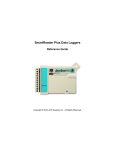
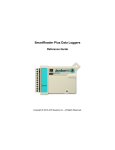
JR Data Loggers
Reference Guide
Copyright © 2010 ACR Systems Inc. All Rights Reserved.
JR Data Loggers
Copyright © 2010 ACR Systems Inc. All Rights Reserved.
All rights reserved. No parts of this work may be reproduced in any form or by any means
- graphic, electronic, or mechanical, including photocopying, recording, taping, or
information storage and retrieval systems - without the written permission of ACR
Systems Inc.
Products that are referred to in this document may be either trademarks and/or registered
trademarks of the respective owners. The publisher and the author make no claim to
these trademarks. For more information regarding trademarks, see the "Trademark
Notices" section of this manual.
ACR Systems Inc. assumes no responsibility for errors or omissions, or for damages
resulting from the use of information contained in this document or from the use of
programs and source code that may accompany it. In no event shall the publisher and the
author be liable for any loss of profit or any other commercial damage caused or alleged
to have been caused directly or indirectly by this document.
TRADEMARK NOTICES
TrendReader is a Registered Trademark of ACR Systems Inc.
LIMITED WARRANTY
ACR Systems Inc. warrants the hardware to be free from defects in workmanship and
components provided they are not abused or subjected to detrimental conditions. Refer to
the warranty information included with your logger for details.
Software is warranted for one year from the date of purchase, to operate in accordance
with its programmed instructions. It is not warranted to be error-free. If the product does
not perform in accordance with this Limited Warranty, ACR will at its discretion, either
repair or replace the product free of charge. There will, however, be a charge for freight
and Canadian Customs clearance (if applicable). Any replacement hardware or software
will be warranted for the remainder of the original warranty period. To the maximum
extent permitted by applicable laws, ACR Systems Inc. disclaims all other warranties,
either expressed or implied, including but not limited to, implied warranties of fitness for a
particular application. In no event shall ACR Systems Inc. be liable for any
inconveniences, loss, damages, etc., whatsoever arising out of the use of this product.
ACR's policy is not to proceed with any repairs or replacement unless first discussed with
ACR's Technical Support Analysts and an RMA (Return Material Authorization) number is
issued.
Contents
I
Table of Contents
Section I JR-1000/1001 Data Loggers
1
1 Introduction
............................................................................................................................................
to JR-1000/1001
1
Features
...........................................................................................................................................................
1
Description ...........................................................................................................................................................
1
Programmed ...........................................................................................................................................................
Operation
2
How JR Loggers
...........................................................................................................................................................
Take Readings
2
...........................................................................................................................................................
How to Use JR
Loggers
3
...........................................................................................................................................................
Specifications
5
Product Approvals
...........................................................................................................................................................
6
2 JR-1000/1001
............................................................................................................................................
Software Driver
7
Logger Status...........................................................................................................................................................
8
Logger Sampling.................................................................................................................................................
8
Logger Memory .................................................................................................................................................
9
Logger Channels
...........................................................................................................................................................
10
.................................................................................................................................................
Channel Information
10
.................................................................................................................................................
Channel Calibration
12
3 JR-1000/1001
............................................................................................................................................
Temperature Logger
13
Description ...........................................................................................................................................................
13
Setup
...........................................................................................................................................................
13
...........................................................................................................................................................
Troubleshooting
13
4 APPENDIX
............................................................................................................................................
A JR-1000/1001 Sample Rates
15
How a Data Logger
...........................................................................................................................................................
Stores Readings
15
Sample Rate...........................................................................................................................................................
Tables
15
Index
Copyright © 2010 ACR Systems Inc. All Rights Reserved.
18
WELCOME
Congratulations on your purchase of a JR-1000 data logger. We are confident that you
will find it to be a most valuable and useful tool for your data collection applications.
This Reference Guide is designed to be used hand-in-hand with TrendReader Standard
software and frequently refers to TrendReader Standard conventions and procedures. To
get the most from your logger, please take time to familiarize yourself with TrendReader
Standard and its Reference Guide.
For important information on how JR-1000 data loggers work and how to use them, read
the Introduction to JR-1000 chapter. It will give you an overview of how the loggers work
and how to configure them for your application. Next, read the chapter that deals with
JR-1000 logger you have.
JR-1000/1001 Data Loggers
1
SECTION 1 JR-1000/1001 Data Loggers
1.1
Introduction to JR-1000/1001
The JR-1000/1001 data loggers is an easy-to-use, battery-powered data logger. Pocket-sized
and rugged, it can be used in a wide range of environmental and industrial applications. The
JR-1000/1001 directly measures and records temperature variables. It can reliably record
time-based data for later analysis by TrendReader software.
TrendReader software must be installed and ready to run prior to making use of the setup
instructions in this section of the guide.
1.1.1
Features
JR-1000/1001 data loggers features make them a useful tool for data collection:
·
·
·
·
·
·
·
·
·
1.1.2
Pocket-sized
Solid-state components - no moving parts
Low-power microprocessor controlled circuitry
8-bit high resolution readings
Precision on-board thermistor temperature sensor
High capacity lithium battery
Quartz clock crystal
Magnetic backing
Rugged polyurethane encapsulation
Description
JR-1000/1001 loggers can run continuously, constantly measuring and recording readings
from its temperature channel. They can also start logging at a specified time. Self-powered by
a long-life lithium battery that will provide years of reliable operation, your JR-1000/1001 can
work independently from any external power supply or computer. When you are ready to look
at the data it has collected, you can transfer all information to your computer through the use
of TrendReader software.
Copyright © 2010 ACR Systems Inc. All Rights Reserved.
2
JR Data Loggers
Main Components
The main components of the JR-1000/1001 data loggers include:
· a memory chip that has the capacity to store up to 244,800 readings (see
Specifications)
· a microprocessor and an 8-bit analog-to-digital converter (A/D) that converts all
temperature signals to digital values
· a quartz clock crystal that accurately keeps track of time and regulates the taking of
readings
· an accurate on-board thermistor that the logger uses to measure ambient temperature
via changes in resistance
· a lithium battery that provides power to the logger and internal sensors
1.1.3
Programmed Operation
JR-1000/1001 data loggers run according to settings that you program. These pre-selected
settings are stored in the logger's memory and instruct it to:
·
·
·
·
1.1.4
take readings at regularly spaced intervals
associate the channel with an equation in TrendReader software
start readings with or without a delay
take readings continuously, or stop when memory is full
How JR Loggers Take Readings
Each JR-1000/1001 data logger has an on-board temperature sensor that you can use to
record ambient temperature.
JR-1000/1001 data loggers can store readings to memory using one of two sampling methods:
1. First-in, First-out (FIFO). In this method the logger continues to take readings when its
memory is full (to make room, it discards the oldest reading every time it adds a new
one). Thus, the memory will contain a "sliding window" of information.
2. Stop when Full. The logger stops recording when its memory is full.
You can set the time interval at which your logger saves readings using TrendReader
software. At a sample rate of eight seconds, one reading is taken every eight seconds and
saved to memory. JR-1000/1001 data loggers can record readings using one of two modes:
1. Average. As you slow the sample rate the logger begins to average readings before
saving them to memory. To do this the logger takes a reading every eight seconds, but
instead of transferring this directly to the logger's memory, it stores the readings in an
accumulator (a temporary memory) where it is retained until the sampling interval is
over. Then the accumulator is averaged and the result is stored to memory.
2. Spot. The logger records the value of the reading at the selected sample interval and
stores it to memory. No averaging is done.
When you backup a logger's data to your computer, the correct time and date are referenced
to each reading. All readings are then individually time and date stamped and processed by
an equation associated with each logger channel. The result is a collection of accurate
Copyright © 2010 ACR Systems Inc. All Rights Reserved.
JR-1000/1001 Data Loggers
3
time-based data ready for detailed graphing and analysis.
1.1.5
How to Use JR Loggers
Using your JR-1000/1001 data logger for most applications is a simple process. With proper
planning, setup and installation of your data logger, you can be assured that the information
you collect will be both correct and useful. The following provides general procedures for using
JR-1000/1001 data loggers. For additional and specific information on these steps, refer to
the chapter in this manual.
Planning
Proper planning is the key to successful data logging. Time spent in this stage will help you
save time and frustration later. To help you plan, answer these questions:
·
·
·
·
What exactly do I want to measure?
Where is the best place to measure?
How long do I want to monitor for?
Should other variables be monitored simultaneously?
Setup
To set up your JR-1000/1001 data logger you must first have TrendReader software installed
and running on your computer. You can then configure your logger with various options by
connecting it directly to your computer's serial port or via a serial cable.
Set Sample Rate
Always confirm the sample rate (how often the logger saves readings) to make sure it will be
acceptable for your application. You can alter the frequency at which your JR-1000/1001
logger records readings by changing the sample rate. You can choose rates from 8 seconds
to 34 minutes. The sample rate chosen will apply to all the active channels on the logger.
To help determine which sample rate you should choose, answer these questions:
· How long do I need to record data?
· How much time will elapse between when I retrieve the logger and download the data to
my computer (for example, the trip back to the office)?
· How often do readings need to be taken?
Clear Memory
Before starting a logging session, clear the logger's memory. This will help to keep the
collected files smaller as well as decrease the time needed to backup the logger later. Note
that clearing the memory is automatic if you save or apply the setup changes (for example, set
memory compression on or off, change sample rate, etc.).
Test
You can directly read the values that your JR-1000/1001 data logger is sensing using the
Realtime capability of TrendReader software. This test gives you the opportunity to check
your logger setup and make any necessary changes before starting the logging session.
Copyright © 2010 ACR Systems Inc. All Rights Reserved.
4
JR Data Loggers
Label
If you are working with more than one data logger, label each logger, identifying the task and
location before you distribute them throughout a building or system. To do this, you can simply
use a shipping tag. Later, when you retrieve them to graph their data, you will know what each
graph refers to. There is a description field in the Setup that can be used for entering the tag
information. Note that after editing and saving the Description you will need to click Contact to
update the new Description in TrendReader Explorer and in the Diagnostic Log.
Mounting
Use the magnetic backing to conveniently mount your logger on metal surfaces like ductwork
or electrical control cabinets. If you are concerned about theft take advantage of its small size
and hide it completely out of view. Because JR-1000/1001 loggers are so light, you can use
special mounting fasteners like Velcro® to attach them to almost any surface. Make sure your
logger's mounting method will last the full length of your logging session.
Do not rely on the logger's magnetic strip for adhesion if the mounting surface is uneven,
unstable or above 65°C (150°F).
Cold or Humid Environments
Make sure that the environment you will be placing your logger into will be acceptable by
referring to the Specifications in this chapter. If conditions are not adequate for the logger,
consider using a protective enclosure. For humid conditions you can protect your logger
simply by placing it in a zip-lock plastic bag.
When you place your JR-1000/1001 logger in a cold environment, make sure condensation
will not settle on the logger when you bring it back into warmer surroundings, such as an
office. The best way of preventing moisture is to place the logger in a container and include a
desiccant (a material that absorbs moisture). When you bring your logger back to your
computer, leave the logger in the container until it has had a chance to warm up to the
surrounding temperature. You can then take it out and backup the data to be analyzed.
Keep Track
Make sure you keep a record of where you have placed each logger in a building or system
plan. You will save time looking for them when your data gathering session is over. Also,
keep track of when you placed the loggers in the area you are monitoring. This will help when
producing graphs on your computer. It may be helpful to label (shipping tag) each logger so
you can properly identify and differentiate it from other loggers.
Analysis
After sufficient time has passed for the logger to obtain a representative profile of data, it is
time to analyze the information. If you are retrieving the logger from the field, bring it back
immediately to your computer for analysis.
In order to analyze your JR-1000/1001 logger's data, you must first transfer a backup copy of
its data to your computer. To do this, see Backup in the TrendReader guide. After
transferring your information to the computer, the data is automatically copied to disk and time
and date stamped.
You can find a detailed description of all software functions in the TrendReader guide.
Copyright © 2010 ACR Systems Inc. All Rights Reserved.
JR-1000/1001 Data Loggers
1.1.6
5
Specifications
General
Size:
33 x 43 x 20 mm (1.3" x 1.7" x 0.75")
Weight:
35 grams (1.23 ounces)
Enclosure Material:
Polyurethane
Mounting:
Magnetic backing (JR-1000 only)
Operating Limits:
-40°C to 85°C (-40°F to 185°F)
0 to 95% RH (non-condensing)
Clock Accuracy:
±2 seconds/day
Battery:
3.6 Volt Lithium, 0.45 Amp-hour
Battery Life:
5 years under normal use
Memory Size:
32KB
Without Compression: up to 32,640 readings
With Compression: up to 244,800 readings
Memory Usage:
1. Continuous (First-in, First-out)
2. Stop when full (Fill-then-stop)
Sample Intervals:
User-selectable rates from every 8 seconds to 34 minutes.
Sampling Mode:
1. Average (over sample interval except for 8 second
interval)
2. Spot
Resolution:
8-bit (1 part in 256)
Internal Temperature Sensor
Type:
NTC Thermistor 10,000 ohms @ 25°C (77°F)
Range:
-40°C to 85°C (-*40F to 185°F)
Accuracy:
± 0.2°C from 0 to 70°C (± 0.3°F from 32 to 158°F)
Resolution:
0.4°C (0.7°F) @ 25°C ; better than 1°C (1.8°F) between -25°
and 70°C (-13° and 158°F), better than 2.0°C (3.6°F) between
-40° and -25°C (-40° and -13°F)
Calibration:
Factory calibration verification and NIST certificates are
available upon special request.
Equation:
Use Equation [45] ET016 Temperature in TrendReader
software. Other equations for this thermistor type may be
selected but will give incorrect results. You may also create
Copyright © 2010 ACR Systems Inc. All Rights Reserved.
6
JR Data Loggers
your own equations, please refer to the Equations section or
contact Customer Service at ACR Systems.
Specifications are subject to change without notice.
1.1.7
Product Approvals
Certified to CE standard EN61326: 1977 + A1: 1998 (European Emissions and Immunity)
covering Radiated Electromagnetic Field, ESD, and RFI
Meets FCC standard 47 CFR Part 15, Subpart B: 1999, Class B, (US Radiated and Conducted
Emissions)
JR-1001 only:
UL approved intrinsically safe for use in:
Class I, Division 1, Groups A, B, C & D
Class II, Division I, Groups E, F & G
Class III, Division I Hazardous Locations TC3
Copyright © 2010 ACR Systems Inc. All Rights Reserved.
JR-1000/1001 Data Loggers
1.2
7
JR-1000/1001 Software Driver
TrendReader software uses a software driver to communicate with JR-1000/1001 data
loggers. The software driver takes the form of two windows. The Status window, shown when
you contact the logger, is used to display the settings currently stored in the data logger. The
Setup window, shown when you select Edit Setup, is used to alter the current settings and
apply the changes to the data logger. The settings are divided into two main sections: Status
and Channels. Status contains information about sampling, memory and logger description.
The channel of the logger contains information about the channel type (temperature), equation
and Realtime value, and calibration associated with the channel. You can control the level of
detail that you see for the settings by clicking on the "+" and "-" buttons at the left side to
expand and collapse the nodes.
When you want to clear the logger's memory and start a new logging session with the existing
or new parameters, select Edit Setup from TrendReader. In the Edit Logger Setup window,
make any necessary changes. To implement your changes, you can either click on Apply or
OK. OK will implement the changes and close the window whereas Apply will leave the
window open, thereby allowing you to make changes in other features.
Copyright © 2010 ACR Systems Inc. All Rights Reserved.
8
1.2.1
JR Data Loggers
Logger Status
When you contact the logger, the logger status is displayed. The Status line indicates whether
the data logger is actively logging, waiting to start or dormant. If you set up the logger with no
delay, it will immediately start logging and the status will show if the logger is actively logging,
dormant or set to start at a given time. It will also show the status of the logger's capacity.
The Status subsections are Sampling and Memory.
1.2.1.1
Logger Sampling
The sample rate is the frequency with which a logger stores readings to memory. The
Sampling subsection indicates what the sample rate is. In normal sampling, the rates
available are from once every 8 seconds to once every 34 minutes.
To set the sample rate, click on the desired time unit and select the value from the drop-down
list as shown.
To find out more about sample rates and to view a set of sample rate tables, see Appendix A
Sample Rates.
The Mode is the way the logger stores the data. The Average method stores an averaged
reading of the data read every 8 seconds over the sample interval you have chosen if the
sampling mode is set to Average (this does not apply to a sampling interval of 8 seconds). The
Spot method still takes readings every 8 seconds but only stores the reading taken at the
selected interval.
Copyright © 2010 ACR Systems Inc. All Rights Reserved.
JR-1000/1001 Data Loggers
1.2.1.2
9
Logger Memory
The Memory subsection indicates how the data is stored in memory and what the start and
end times (or capacity) are for the data logging. In the FIFO (First In, First Out) mode, the
logger continually stores data and when the memory limit is reached, the new readings start to
overwrite the oldest readings. In this method, the logger is always collecting data, but only
saves the most recent data in its memory. In the Stop When Full mode, when the memory
limit is reached, the logger stops recording.
The length of time for data capture of the logger is determined by the number of active
channels and the sampling rate. To find out more about how the capacity is affected by the
sample rate and active channels, see Appendix A Sample Rates.
To set how the logger stores its data, click on the Usage field and select FIFO or Stop When
Full.
To set the compression method click on the Compression field and select ON. A run length
compression method is used. Run length compression stores the reading plus the number of
consecutive times the same reading was measured. This means that the logger will store 2
values to memory, the data value and a counter value. If the reading were 22°C for 3 sample
periods then the logger would store 22°C and the count of 3. Once the reading changes a
new compression session begins. The compression session will last to a maximum of 15
consecutive readings that are the same. If the 16th reading is still the same a new session will
start.
Note that when the compression is set to ON the Start Time will display as NA in the Status
window. If you want to see that Start Time do a Backup of the logger, the Start Time will be
displayed in the Statistics tab of the graph
Copyright © 2010 ACR Systems Inc. All Rights Reserved.
10
JR Data Loggers
To set when the logger will start recording click on the Start Time field. Next, click on the
small button that appears at the right. This will pop up a form allowing you to set the date and
time. Highlight the date or time and enter the appropriate value. You can also click on the
drop-down list arrow to bring up a calendar. You can set the logger's starting time for just
over 65535*8 seconds (6 days, 1 hour, 38 minutes) ahead of the current time. Note that the
start time will default to the closest time sampling within 8 seconds of the selected time.
1.2.2
Logger Channels
The Channels section indicates provides information specific to the channel. The channel on
the logger is always enabled and continually recording readings and storing them in the
logger's memory. The Channel subsections are Channel Information and Channel Calibration.
1.2.2.1
Channel Information
When you contact the logger, the logger status is displayed. The Channel line gives the
description and the Realtime value, if Realtime is turned on. The Description field is editable.
The Realtime value is based on the equation that you select for the channel. The equation is
selected in the Setup window but is not shown in the Status window.
Copyright © 2010 ACR Systems Inc. All Rights Reserved.
JR-1000/1001 Data Loggers
11
The logger collects and stores raw data readings. An equation is used to transform the raw
data into measurement units, such as °C, with the current reading shown as a Realtime value.
You can use built-in equations or you can create your own custom equations. See Equations
in the TrendReader guide for further information. To set the equation, click on the Equation
field and select the equation from the drop-down list. To help you select the proper equation,
the Realtime value using the currently selected equation is shown. *
* Note that if a custom equation is not available when Edit Setup... is selected (e.g.: deleted)
then the equation will be shown as unknown. If a new equation is not selected the Realtime
value will not display correctly. If the logger is backed up the channel will be disabled then
changes to the equation can be made in the graph using the Lines Tab in Graph Settings."
Copyright © 2010 ACR Systems Inc. All Rights Reserved.
12
1.2.2.2
JR Data Loggers
Channel Calibration
The Calibration subsection shows the Low, Mid, High, and Ext calibration values. These
values are used to adjust the readings of the logger in order to make the output more
accurate. To set each calibration value, click on the appropriate calibration field and enter the
value. The factory equations for the JR-1000/1001 use the Low, Mid, and High values as
offset and span. Ext values are not used.
Note that the calibration values are based on 255 increments between -5 and +5, the field will
default to the closest value of what is entered. E.g.: -4.9 will default to -4.8828125.
Copyright © 2010 ACR Systems Inc. All Rights Reserved.
JR-1000/1001 Data Loggers
1.3
13
JR-1000/1001 Temperature Logger
A self-contained temperature logger, the JR-1000/1001 can be used easily in a wide variety of
applications to collect temperature data.
1.3.1
Description
The JR-1000/1001 is a single channel, low-cost temperature loggers featuring 5-year battery
life and the ability to record for up to 244,800 readings with Compression turned on. Available
in an intrinsically safe version (JR-1001), these loggers are extremely easy to use.
With its precision calibrated internal temperature sensor simply place the logger in the field
and leave it to record. Once the desired information has been recorded plug the logger into the
serial port of your computer and begin downloading and viewing the logged data.
1.3.2
Setup
Once the logger is connected to your computer select the communications port in
TrendReader and click Scan For Loggers.
Channel
0
Description
Internal Temperature
Equation
45
NOTE: The temperature channel is enabled by default.
1.3.3
Troubleshooting
If you are getting what appear to be wrong readings, consider the following before recalibrating
the sensors. Sensors sample the atmosphere (or medium) only in the immediate vicinity of
the sensors themselves. The physical state of the atmosphere and its degree of uniformity
and turbulence will limit the validity of a measurement at some distance from the sensor. This
becomes especially apparent for the measurement of ambient temperature
In a room, temperature levels may vary dramatically from location to location. Such factors as
Copyright © 2010 ACR Systems Inc. All Rights Reserved.
14
JR Data Loggers
air stratification, drafts, and proximity to heat or humidity sources (people, equipment,
moisture, solar gain, etc.) can contribute to a wide variance in conditions even within a small,
confined area. The individual sensor associated with your JR-1000/1001 measures and
records temperature only in one location. They do not, in any way, represent an overall
reading.
Copyright © 2010 ACR Systems Inc. All Rights Reserved.
JR-1000/1001 Data Loggers
1.4
15
APPENDIX A JR-1000/1001 Sample Rates
JR-1000/1001 Sample Rates
1.4.1
How a Data Logger Stores Readings
The sample rate of your data logger is the frequency with which it stores readings in its
memory. A selected sample rate applies to the channel on a JR-1000/1001.
If you set your data logger's sample rate to eight seconds, it reads it's input channel and stores
the reading once every eight seconds. If you choose a sample rate longer than eight seconds,
the logger still reads it's input channel once every eight seconds, and stores an averaged
reading at the end of the sample interval you have chosen if the sampling mode is set to
Average.
For example, if you use a two-minute sample rate, the data logger takes fifteen separate
readings over each two-minute interval. At the end of each two-minute interval, the logger
calculates the average of the fifteen readings, and stores that average in its memory.
Otherwise if the sampling mode is set to Spot the logger still takes readings every 8 seconds
but only stores the reading taken at the selected interval.
1.4.2
Sample Rate Tables
The following tables list the maximum time spans over which your JR-1000/1001 will record
readings. The time spans depend on the length of the sample rate. A JR-1000/1001 has a
memory capacity of up to 244,800 readings when data compression is selected and up to
32,640 readings when data compression not selected.
In each table, the Sample Rate column lists the available sample rates. The Days, Hours,
Minutes and Seconds columns list the time spans over which your logger will record readings
at each sample rate.
For example, a JR-1000/1001 using a sample rate of ten minutes and without compression will
store readings for 226 days and 16 hours. After that time, depending on how it was set up, the
logger will either continue to take readings and replace the oldest readings with the new
readings (FIFO), or it will stop taking readings (Stop When Full).
Table B-1: JR-1000/1001 Sample Rate Table with Compression (max)
Sample Rate
Years
Days
Hours
Minutes
Seconds
8 sec.
0
22
16
0
0
16 sec.
0
45
8
0
0
Copyright © 2010 ACR Systems Inc. All Rights Reserved.
16
JR Data Loggers
32 sec.
0
90
16
0
0
56 sec.
0
158
16
0
0
2 min.
0
340
0
0
0
4 min. 56 sec.
2
108
16
0
0
10 min.
4
240
0
0
0
20 min.
9
115
0
0
0
30 min.
13
355
0
0
0
Table B-2: JR-1000/1001 Sample Rate Table with Compression (min)
Sample Rate
Years
Days
Hours
Minutes
Seconds
8 sec.
0
1
12
16
0
16 sec.
0
3
0
32
0
32 sec.
0
6
1
4
0
56 sec.
0
10
13
52
0
2 min.
0
22
16
0
0
4 min. 56 sec.
0
55
21
52
0
10 min.
0
113
8
0
0
20 min.
0
226
16
0
0
30 min.
1
88
8
0
0
Table B-3: JR-1000/1001 Sample Rate Table with Compression (5 times)
Sample Rate
Years
Days
Hours
Minutes
Seconds
8 sec.
0
15
2
40
0
16 sec.
0
30
5
20
0
32 sec.
0
60
10
40
0
56 sec.
0
105
18
40
0
2 min.
0
226
16
0
0
4 min. 56 sec.
1
194
2
40
0
10 min.
3
38
8
0
0
20 min.
6
76
16
0
0
30 min.
12
153
0
0
0
Table B-4: JR-1000/1001 Sample Rate Table without Compression
Sample Rate
Years
Days
Hours
Minutes
Seconds
8 sec.
0
3
0
32
0
16 sec.
0
6
1
4
0
Copyright © 2010 ACR Systems Inc. All Rights Reserved.
JR-1000/1001 Data Loggers
32 sec.
0
12
2
8
0
56 sec.
0
21
3
44
0
2 min.
0
45
8
0
0
4 min. 56 sec.
0
111
19
44
0
10 min.
0
226
16
0
0
20 min.
1
88
8
0
0
30 min.
1
315
0
0
0
Copyright © 2010 ACR Systems Inc. All Rights Reserved.
17
18
JR Data Loggers
Index
-DData Logger 1
-JJR 13
Approvals 6
Channel Calibration 12
Channel Information 10
Channels 10
Data Logger 1
Description 1
Features 1
How to Use 3
Introductions 1
Logger 1
Memory 9
Operation 2
Readings 2
Sampling 7, 8
Setup 7
Software 7
Specifications 5
Status 7, 8
Unknown Equation 10
-LLogger 1
-SSample Rates 15
-TTemperature 13
Copyright © 2010 ACR Systems Inc. All Rights Reserved.
ACR Systems Inc.
Building 210 - 12960 84th Ave.
Surrey, British Columbia, Canada V3W 1K7
Telephone: (604) 591-1128
North American Toll Free: 1-800-663-7845
Fax: (604) 591-2252
General Enquiries Email: [email protected]
Sales Department Email: [email protected]
Customer Service Email: [email protected]
www.acrsystems.com


