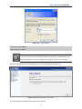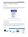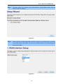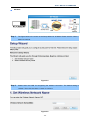
1
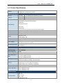
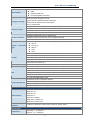
Copyright Copyright 2011 by PLANET Technology Corp. All rights reserved. No part of this publication may be reproduced, transmitted, transcribed, stored in a retrieval system, or translated into any language or computer language, in any form or by any means, electronic, mechanical, magnetic, optical, chemical, manual or otherwise, without the prior written permission of PLANET. PLANET makes no representations or warranties, either expressed or implied, with respect to the contents hereof and specifically disclaims any warranties, merchantability or fitness for any particular purpose. Any software described in this manual is sold or licensed "as is". Should the programs prove defective following their purchase, the buyer (and not this company, its distributor, or its dealer) assumes the entire cost of all necessary servicing, repair, and any incidental or consequential damages resulting from any defect in the software. Further, this company reserves the right to revise this publication and to make changes from time to time in the contents hereof without obligation to notify any person of such revision or changes. All brand and product names mentioned in this manual are trademarks and/or registered trademarks of their respective holders. Federal Communication Commission Interference Statement This equipment has been tested and found to comply with the limits for a Class B digital device, pursuant to Part 15 of FCC Rules. These limits are designed to provide reasonable protection against harmful interference in a residential installation. This equipment generates, uses, and can radiate radio frequency energy and, if not installed and used in accordance with the instructions, may cause harmful interference to radio communications. However, there is no guarantee that interference will not occur in a particular installation. If this equipment does cause harmful interference to radio or television reception, which can be determined by turning the equipment off and on, the user is encouraged to try to correct the interference by one or more of the following measures: 1. Reorient or relocate the receiving antenna. 2. Increase the separation between the equipment and receiver. 3. Connect the equipment into an outlet on a circuit different from that to which the receiver is connected. 4. Consult the dealer or an experienced radio technician for help. FCC Caution: To assure continued compliance, (example-use only shielded interface cables when connecting to computer or peripheral devices) any changes or modifications not expressly approved by the party responsible for compliance could void the user’s authority to operate the equipment. This device complies with Part 15 of the FCC Rules. Operation is subject to the Following two conditions: (1) This device may not cause harmful interference (2) This Device must accept any interference received, including interference that may cause undesired operation. Any changes or modifications not expressly approved by the party responsible for compliance could void the user’s authority to operate the equipment. I Federal Communication Commission (FCC) Radiation Exposure Statement This equipment complies with FCC radiation exposure set forth for an uncontrolled environment. In order to avoid the possibility of exceeding the FCC radio frequency exposure limits, human proximity to the antenna shall not be less than 20 cm (8 inches) during normal operation. CE mark Warning This is a class B device, in a domestic environment; this product may cause radio interference, in which case the user may be required to take adequate measures. Energy Saving Note of the Device This power required device does not support Stand by mode operation. For energy saving, please remove the DC-plug or push the hardware Power Switch to OFF position to disconnect the device from the power circuit. Without remove the DC-plug or switch off the device, the device will still consuming power from the power circuit. In the view of Saving the Energy and reduce the unnecessary power consuming, it is strongly suggested to switch off or remove the DC-plug for the device if this device is not intended to be active. R&TTE Compliance Statement This equipment complies with all the requirements of DIRECTIVE 1999/5/CE OF THE EUROPEAN PARLIAMENT AND THE COUNCIL OF 9 March 1999 on radio equipment and telecommunication terminal Equipment and the mutual recognition of their conformity (R&TTE). The R&TTE Directive repeals and replaces in the directive 98/13/EEC (Telecommunications Terminal Equipment and Satellite Earth Station Equipment) As of April 8, 2000. Safety This equipment is designed with the utmost care for the safety of those who install and use it. However, special attention must be paid to the dangers of electric shock and static electricity when working with electrical equipment. All guidelines of this and of the computer manufacture must therefore be allowed at all times to ensure the safe use of the equipment. National Restrictions This device is intended for home and office use in all EU countries (and other countries following the EU directive 1999/5/EC) without any limitation except for the countries mentioned below: Country Restriction Bulgaria None France Reason/remark General authorization required for outdoor use and public service Outdoor use limited to 10 Military Radiolocation use. Refarming of the 2.4 GHz mW e.i.r.p. within the band band has been ongoing in recent years to allow current 2454-2483.5 MHz relaxed regulation. Full implementation planned 2012 II Italy None Luxembourg None Norway Implemented Russian Federation None If used outside of own premises, general authorization is required General authorization required for network and service supply(not for spectrum) This subsection does not apply for the geographical area within a radius of 20 km from the centre of Ny-Ålesund Only for indoor applications WEEE Regulation To avoid the potential effects on the environment and human health as a result of the presence of hazardous substances in electrical and electronic equipment, end users of electrical and electronic equipment should understand the meaning of the crossed-out wheeled bin symbol. Do not dispose of WEEE as unsorted municipal waste and have to collect such WEEE separately. Revision User’s Manual for PLANET 802.11n Wireless Portable AP / Router Model: WNRT-300 Rev: 1.0 (June, 2011) Part No. EM-WNRT-300_v1.0 (2081-E50230-000) III CONTENTS Chapter 1. Product Introduction.......................................................................................................... 1 1.1. Package Contents ......................................................................................................... 1 1.2. Product Description .......................................................................................................1 1.3. Product Features........................................................................................................... 2 1.4. Product Specification.....................................................................................................4 Chapter 2. Hardware Interface ............................................................................................................. 7 2.1. Overview........................................................................................................................ 7 2.2. LED Indications ............................................................................................................. 7 Chapter 3. Installation Guide ............................................................................................................... 9 3.1. System Requirements ................................................................................................... 9 3.2. Typical Application......................................................................................................... 9 3.2.1. Router Mode........................................................................................................ 9 3.2.2. AP Mode ............................................................................................................10 3.2.3. Client Mode .......................................................................................................10 3.3. Manual Network Setup - TCP/IP Configuration........................................................... 11 3.3.1. Obtain an IP Address Automatically .................................................................. 11 3.3.2. Configure the IP address manually ...................................................................13 3.4. Hardware Installation...................................................................................................14 3.5. Starting Setup in Web UI .............................................................................................16 Chapter 4. Configuration in Web UI...................................................................................................18 4.1. Login............................................................................................................................18 4.2. Setup Wizard...............................................................................................................18 4.3. Operation Mode...........................................................................................................23 4.4. Wireless.......................................................................................................................24 4.4.1. Basic Settings....................................................................................................24 4.4.2. Advanced Settings.............................................................................................26 4.4.3. Security..............................................................................................................29 4.4.4. Access Control...................................................................................................30 4.4.5. WDS Settings ....................................................................................................31 4.4.6. Site Survey ........................................................................................................32 4.4.7. WPS ..................................................................................................................33 4.4.8. Schedule............................................................................................................33 4.5. TCP/IP Settings ...........................................................................................................34 4.5.1. LAN Interface.....................................................................................................34 4.5.2. WAN Interface ...................................................................................................36 IV 4.6. Firewall ........................................................................................................................37 4.6.1. Port Filtering ......................................................................................................38 4.6.2. IP Filtering .........................................................................................................39 4.6.3. MAC Filtering.....................................................................................................39 4.6.4. Port Forwarding .................................................................................................40 4.6.5. URL Filtering......................................................................................................42 4.6.6. DMZ...................................................................................................................42 4.6.7. VLAN .................................................................................................................43 4.7. QoS .............................................................................................................................45 4.8. Route Setup ................................................................................................................46 4.9. Management ...............................................................................................................47 4.9.1. Status.................................................................................................................47 4.9.2. Statistics ............................................................................................................48 4.9.3. DDNS ................................................................................................................49 4.9.4. Time Zone Setting .............................................................................................50 4.9.5. Denial of Service ...............................................................................................50 4.9.6. Log.....................................................................................................................51 4.9.7. Upgrade Firmware.............................................................................................52 4.9.8. Save/Reload Settings........................................................................................53 4.9.9. Password...........................................................................................................54 4.10. Logout........................................................................................................................54 Chapter 5. Quick Connection to a Wireless Network ......................................................................55 5.1. Windows XP (Wireless Zero Configuration)................................................................55 5.2. Windows 7 (WLAN AutoConfig) ..................................................................................57 5.3. Mac OS X ....................................................................................................................60 5.4. iPhone / iPod Touch / iPad ..........................................................................................64 Appendix ..............................................................................................................................................67 V User’s Manual of WNRT-300 Chapter 1. Product Introduction 1.1. Package Contents The following items should be contained in the package: WNRT-300 Portable AP/Router Power Adapter USB Cable Ethernet Cable Li-ion Battery Quick Installation Guide CD-ROM (User’s Manual included) If there is any item missed or damaged, please contact the seller immediately. 1.2. Product Description Multiple Wireless Network Technologies for Greater Access PLANET Wireless Portable Broadband Router, the WNRT-300 features 802.11n radio with 1T1R antenna technology compliant with 802.11b/g/n standards. Compared with general wireless routers, the WNRT-300 offers more powerful and flexible capability for business demands to access Internet with true mobility and range extension of wireless network. More Flexibility and Mobility With the tiny-sized and stylish design, the WNRT-300 is easy to carry for the true mobility. It can operate in various environments with the hardware switch modes including AP, Router, and Client, which helps to immediately set up a wireless network without software configuration. The portable design and operation flexibility make the WNRT-300 suitable for travelling, moving and outdoor applications. -1- User’s Manual of WNRT-300 Built-in High Capacity Battery The WNRT-300 has one built-in rechargeable lithium battery and its power supplied through mini USB interface. The power can be directly charged via the computer's USB port which increases the convenience even when there is no power outlet available. One-touch Secure Wireless Connection In order to simplify security settings for home and SOHO network, the WNRT-300 supports Wi-Fi Protected Setup (WPS) with configuration in PBC and PIN type. Just push the WPS button or key in the PIN code, the secure connection between the WNRT-300 and the wireless clients can be built immediately, which offers users a convenient and fast method to construct a secure wireless network. Wide Range of Wireless Security Support To secure the wireless communication, the WNRT-300 supports most up-to-date encryptions including WPA/WPA2-PSK with TKIP/AES. Made to fulfill enterprise and various applications demand, the WNRT-300 enhances security and management features such as multiple SSID and IEEE 802.1Q VLAN support. It can create up to 5 virtual standalone AP with 5 different SSID according to individual security levels and encryption scheme of various wireless devices. Even more, the VLAN support allows multiple SSID to access Internal VLAN topology. Advanced Firewall Security In the Router mode, the WNRT-300 supports NAT functions and allows multiple users to access Internet via only one single legal IP. It provides Port Forwarding and DMZ for LAN PC to act as an application server. Furthermore, the advanced firewall by the WNRT-300 can protect your Intranet clients from unauthorized accesses and various DoS attacks from the Internet. In aspect of the firewall, the WNRT-300 provides IP/ MAC/ Port/ URL filtering, and prevents possible hackers attack. Easy Setup Anytime Anywhere The WNRT-300 provides a total solution for home and business users. With the High Speed 802.11n wireless technology, the WNRT-300 is easy to integrate the wireless devices with existing wired network. 1.3. Product Features Industrial Compliant Wireless LAN & LAN -2- User’s Manual of WNRT-300 Compliant with IEEE 802.11n wireless technology capable of up to 150Mbps data rate Backward compatible with 802.11b/g standard Equipped with one 10/100Mbps RJ-45 Ethernet port for LAN/WAN, Auto MDI/MDI-X supported Wireless Network Range Extender Multiple Wireless Modes: AP, WDS, Repeater, Universal Repeater, Client Supports WMM (Wi-Fi Multimedia), Wireless QoS Supports IAPP (Inter Access Point Protocol), Wireless Roaming Fixed-network Broadband Router Supported Internet types: Dynamic IP/ Static IP/ PPPoE/ L2TP/ PPTP Supports Static & Dynamic (RIP1 and 2) Routing Supports IP / MAC-Based Bandwidth Control Supports 802.1d STP & IGMP Proxy Secure Network Connection Advanced security: 64/128-bit WEP, WPA-Enterprise/ WPA2-Enterprise and WPA-PSK/WPA2-PSK with TKIP/AES Encryption, 802.1x Authentication Built-in NAT firewall features with Port/ IP/ MAC/ URL Filtering, and DoS protection Supports 802.1Q VLAN Advanced Networking Function for Specific Application Supports multiple sessions IPSec, L2TP, PPTP, and IPv6 VPN pass-through Supports Port Forwarding, DMZ, UPnP and Dynamic DNS for various networking applications Supports DHCP Server Easy to Install & Management Web-Based UI and setup Wizard for easy configuration System status monitoring includes DHCP Client and System Log Flexible Application & Business-oriented design Portable and Pocket-sized design for true mobility Hardware switchable operation modes: Router / AP / Client One-touch Wi-Fi Protected Setup (WPS) Built-in rechargeable Li-ion battery -3- User’s Manual of WNRT-300 1.4. Product Specification Product WNRT-300 150Mbps 802.11n Wireless AP / Router Hardware Specification Interface Antenna LAN/WAN 1 x 10/100Mbps Auto MDI/MDI-X RJ45 port Gain: 1 x Internal 2dBi Antenna Orientation: Omni-directional Front panel (from left to right): Mode Selection Switch (Router/Client/AP) WPS Button Button/Switch Power On/Off Switch Rear panel: Reset button *Push for above 5 seconds to reset to factory default settings LED Indicators PWR, WLAN, WAN/LAN, WPS, CHG Material Plastic Dimension (W x D x H) 88 x 62 x 18 mm Weight With battery: 80g Without battery: 58g Battery Built-in Rechargeable Li-ion Battery (3.7V, 1050mAh) Power Requirement DC 5V , 0.4A maximum, connected through mini-USB connector Power Adapter Standard Accessory AC Input: 100~240V AC (50/60Hz) DC Output: 5V with max. 1A current Power Adapter x 1, USB Cable x 1, Ethernet Cable x 1, Li-ion Battery x 1, CD-ROM x 1, Quick Guide x 1 Wireless Interface Specification Standard Compliance with IEEE 802.11b/g/n Frequency Band 2.4~2.4835GHz Extend Frequency DSSS Modulation Type DBPSK, DQPSK, QPSK, CCK and OFDM (BPSK/QPSK/16-QAM/ 64-QAM) Data Transmission Rates Transmission Distance 11n: Up to 150Mbps (Dynamic) 11g: Up to 54Mbps (Dynamic) 11b: Up to 11Mbps (Dynamic) Indoor up to 100m outdoor up to 300m (it is limited to the environment) America/ FCC: 2.412~2.462GHz (11 Channels) Channel Europe/ ETSI: 2.412~2.472GHz (13 Channels) Japan/ TELEC: 2.412~2.484GHz (14 Channels) Max. RF Power 20 dBm (EIRP) 135M: -68dBm@10% PER Receive Sensitivity 54M: -68dBm@10% PER 11M: -85dBm@8% PER Software Features Operation Mode AP Router Client (Switchable by H/W) -4- User’s Manual of WNRT-300 Wireless Mode AP WDS Repeater (WDS+AP) Universal Repeater (AP+Client) WEP (64/128-bit) encryption security Encryption Security WPA-Enterprise / WPA2-Enterprise (TKIP/AES) WPA-Personal / WPA2-Personal (TKIP/AES) 802.1x Authentication Provide wireless LAN ACL (Access Control List) filtering Wireless Security Wireless MAC address filtering Support WPS (Wi-Fi Protected Setup) Enable/Disable SSID Broadcast WMM(Wi-Fi Multimedia): 802.11e Wireless QoS Wireless Advanced IAPP(Inter Access Point Protocol): 802.11f Wireless Roaming Provide Wireless Statistics Shares data and Internet access for users, supporting following internet access: Internet Connection Type PPPoE Dynamic IP Static IP PPTP L2TP NAT firewall with SPI (Stateful Packet Inspection) Built-in NAT server supporting Port Forwarding, and DMZ Firewall Built-in firewall with IP address/ MAC address/ Port/ URL filtering Support ICMP-FLOOD, UDP-FLOOD, TCP-SYN-FLOOD filter, DoS protection Support 802.1Q VLAN up to 4 Routing Protocol VPN Pass-through Static / Dynamic (RIP1 and 2) Routing PPTP, L2TP, IPSec, IPv6 Built-in DHCP server supporting static IP address distributing Support UPnP, Dynamic DNS LAN Support IGMP Proxy Support 802.1d STP (Spanning Tree) IP / MAC-based Bandwidth Control Web-based (HTTP) management interface System Management SNTP time synchronize Easy firmware upgrade System Log supports Remote Log Standards Conformance IEEE 802.11n (1T1R, up to 150Mbps) IEEE 802.11g IEEE 802.11b IEEE Standards IEEE 802.11i IEEE 802.3 10Base-T IEEE 802.3u 100Base-TX IEEE 802.3x Flow Control Others Protocols and Standards CSMA/CA, CSMA/CD, TCP/IP, DHCP, ICMP, NAT, PPPoE, SNTP Environment Temperature Operating: 0 ~ 40 Degree C Storage: -40 ~ 70 Degree C -5- User’s Manual of WNRT-300 Humidity Operating: 10 ~ 90% (Non-Condensing) Storage: 5 ~ 90% (Non-Condensing) -6- User’s Manual of WNRT-300 Chapter 2. Hardware Interface 2.1. Overview Front Panel Figure 2-1 Rear Panel Figure 2-2 Object WPS Button Reset Description Press the button for about 5 seconds to activate the WPS function. Reset the WNRT-300 to the factory default settings by holding the Reset button and pressing down for about 5 seconds. 2.2. LED Indications The LEDs on the top panel indicate the instant status of system power, wireless data activity, WPS, port links, battery, and help monitor and troubleshoot when needed. Figure 2-3 and Table 2-1 show the LED indications of the WNRT-300. -7- User’s Manual of WNRT-300 Figure 2-3 Top Panel LED Definition LED Power WLAN WPS WAN/LAN COLOR Green Blue Blue Blue STATE On Device power on Off Device power off Flash Low battery power Flash The Wireless function is enabled. Off The Wireless function is disabled. On WPS is activated Off WPS is not activated On Link is established Off No Ethernet device connected Flash Battery Status Red FUNCTION Packets are transmitting or receiving On Charging Off Charging complete/ no external power input Table 2-1 -8- User’s Manual of WNRT-300 Chapter 3. Installation Guide 3.1. System Requirements Broadband Internet Access Service (Cable / xDSL / Ethernet connection) One Cable/xDSL Modem that has an RJ-45 connector (not necessary if the WNRT-300 is connected directly to the Ethernet.) PCs with a working Ethernet Adapter and an Ethernet cable with RJ-45 connectors PC of subscribers running Windows 98/ME, NT4.0, 2000/XP, Windows Vista / Win 7, MAC OS 9 or later, Linux, UNIX or other platform compatible with TCP/IP protocols Above PC installed with WEB Browser It is recommended to use Internet Explore 7.0 or above to access the WNRT-300. 3.2. Typical Application Please shift the hardware switch on the WNRT-300 to change the operation mode. 3.2.1. Router Mode In Router Mode, the NAT (Network Address Translation) function and DHCP server are both enabled, and all wireless clients share the same public IP assigned by ISP through WAN port of the WNRT-300. The WNRT-300 is supposed to connect with the Cable / xDSL Modem by UTP cable. Figure 3-1 -9- User’s Manual of WNRT-300 3.2.2. AP Mode In AP Mode, the NAT (Network Address Translation) function and DHCP server are both disabled, and all wireless clients obtain the IP address from the network device connected with LAN port of the WNRT-300. They can certainly assign the IP address for themselves as well in the Control Panel of Windows. The WNRT-300 is supposed to bridge to the Ethernet directly by UTP cable. Figure 3-2 3.2.3. Client Mode In Client Mode, the WNRT-300 is supposed to act as a wireless station for the PC. Users can site survey the available local AP and choose someone to connect with. Figure 3-3 -10- User’s Manual of WNRT-300 3.3. Manual Network Setup - TCP/IP Configuration The default IP address of the WNRT-300 is 192.168.1.1, and the default Subnet Mask is 255.255.255.0. These values can be changed as you desire in the web UI of the WNRT-300. In this section, we use all the default values for description. No matter you want to configure the WNRT-300 via wired or wireless connection, the PC need to be assigned an IP address first. Before you connect the local PC to the WNRT-300 via wired or wireless connection, please configure the IP address for your PC in the following two ways first. Obtain an IP address automatically Configure the IP address manually The following sections will introduce how to install and configure the TCP/IP correctly in Windows XP. First, make sure your Ethernet Adapter is working, and refer to the Ethernet adapter’s manual if needed. 3.3.1. Obtain an IP Address Automatically If you are sure the DHCP server of WNRT-300 is enabled (the default setting of Router Mode), you can set up the TCP/IP Protocol in "Obtain an IP address automatically" mode on your PC. And then the WNRT-300 built-in DHCP server will assign an IP address to the PC automatically. 1) On the Windows taskbar, click the Start button, point to Settings, and then click Control Panel. 2) Double-click the Network Connections icon. Then right-click on the Wireless Network Connection, and select Properties in the appearing window. Figure 3-4 -11- User’s Manual of WNRT-300 3) In the prompt window shown below, double click on the Internet Protocol (TCP/IP). Figure 3-5 4) Choose Obtain an IP address automatically, and Obtain DNS server automatically as shown in the figure below. Then click OK to save your settings. Figure 3-1 -12- User’s Manual of WNRT-300 3.3.2. Configure the IP address manually If you are sure the DHCP server of WNRT-300 is disabled (the default setting of AP Mode and Client Mode), you can configure the IP address manually. The IP address of your PC should be 192.168.1.xxx (the same subnet of the IP address of WNRT-300, and "xxx" is any number from 2 to 254), Subnet Mask is 255.255.255.0, and the Gateway is 192.168.1.1 (The default IP address of WNRT-300) 1) Continue the settings from the last figure, select Use the following IP address radio button. 2) If the LAN IP address of the WNRT-300 is 192.168.1.1, enter IP address 192.168.1.x (x is from 2 to 254), and Subnet mask 255.255.255.0. 3) Enter the LAN IP address of the WNRT-300 (the default IP is 192.168.1.1) into the Default gateway field. 4) Select Use the following DNS server addresses radio button. In the Preferred DNS Server field, you can enter the DNS server IP address provided by your local ISP. Then click OK to save your settings. Figure 4-2 -13- User’s Manual of WNRT-300 3.4. Hardware Installation Please follow the instruction below to build the wireless network connection between WNRT-300 and your computers. Before you start using the WNRT-300, please follow the procedures below to install and charge the battery. Step 1: Remove the battery cover, and insert the attached battery into the slot. Then replace the cover back. Step 2: Charge the battery by the attached power adapter and USB cable. The red LED will be lit up. Step 3: The battery needs to be charged for 8 hours in the first time. When the battery is fully charged, the red LED will be off. Before installing the WNRT-300, make sure your PC is connected to the Internet through the broadband service successfully at this moment. If there is any problem, please contact your local ISP. After that, please install the WNRT-300 according to the following steps. Step 1. Please shift the hardware switch on the WNRT-300 to the operation mode you want to use, and follow the figure below to install it for the purpose of configuration. -14- User’s Manual of WNRT-300 Figure 3-4 Step 2. Please turn on the WNRT-300. Figure 3-6 The procedures of hardware installation are finished. Please continuously follow the next section to start setup in the web UI. If you want to configure the WNRT-300 via wireless connection, please use your PC to site survey the wireless signal of WNRT-300, and connect your PC with it wirelessly. Default SSID: default *Default Wireless Security: None -15- User’s Manual of WNRT-300 Figure 3-5 3.5. Starting Setup in Web UI It is easy to configure and manage the WNRT-300 via web browser. To access the web UI of the WNRT-300, please open a web browser and enter the default IP address http://192.168.1.1 in the address field of the browser. Figure 3-7 After a moment, a login window will appear. Enter the User Name and Password. Then click the OK button. -16- User’s Manual of WNRT-300 Figure 3-8 Login Window Default User name: admin Default Password: admin If the above screen does not pop up, it may mean that your web-browser has been set to a proxy. Go to Tools menu>Internet Options>Connections>LAN Settings, in the screen that appears, cancel the Using Proxy checkbox, and click OK to finish it. After you enter the username and password, the main screen appears as Figure 3-9 Figure 3-9 WNRT-300 Web UI Screenshot The next chapter will introduce the functions of the web UI. -17- User’s Manual of WNRT-300 Chapter 4. Configuration in Web UI 4.1. Login After successfully logging into the web UI of the WNRT-300, you will see the main menus on the left side of the web-based utility. There are some different options appear as the operation mode changes. For example, the figure below is the menus of Router Mode in the web UI. Figure 4-1 The Menu of Router Mode in The Web UI The details for the functions in each operation mode are listed in the following sections. 4.2. Setup Wizard No matter what operation mode you switch to on the WNRT-300, the first screen you enter into the web UI is the Setup Wizard. It will guide the user to configure the WNRT-300 easily and quickly. There are different procedures in different operation modes. According to the operation mode you switch to, please follow the instructions below to configure the WNRT-300 via Setup Wizard. Router Mode -18- User’s Manual of WNRT-300 Step 1. The figure below is the screen of the Setup Wizard in Router Mode. Please click the “Next>>” button to continue. Figure 4-2 Step 2. Please select the corresponding WAN connection type of your Internet service, and fill the correct parameters in the blanks. Then click the “Finished” button to save the settings and reboot to take effect. Figure 4-3 -19- User’s Manual of WNRT-300 AP Mode Step 1. The figure below is the screen of the Setup Wizard in AP Mode. Please click the “Next>>” button to continue. Figure 4-4 Step 2. Please enter the SSID for recognizing the wireless connection. The default setting is “default”. Then click the “Next>>” button to continue. Figure 4-5 -20- User’s Manual of WNRT-300 Step 3. Please select the wireless security mode, and setup the password for wireless connection. Then click the “Finished” button to save the settings and reboot to take effect. Figure 4-6 Client Mode Step 1. The figure below is the screen of the Setup Wizard in Client Mode. Please click the “Next>>” button to continue. -21- User’s Manual of WNRT-300 Figure 4-7 Step 2. Please enter the SSID of the AP you want to connect with, or you can click the “Site Survey” button to search the available local AP. The details of the available AP will appear. Then choose the AP you want to connect to, and click the “Next>>” button to continue. Figure 4-8 Step 3. Please select the correct encryption method of the AP you chose before, and enter the password of it. Then click the “Finished” button to save the settings and reboot to take effect. -22- User’s Manual of WNRT-300 Figure 4-9 4.3. Operation Mode This page shows the current operation mode, but users can only change it by shifting the hardware switch on the WNRT-300. Figure 4-10 -23- User’s Manual of WNRT-300 4.4. Wireless The Wireless menu contains submenus of the settings about wireless network. Please refer to the following sections for the details. Figure 4-11 4.4.1. Basic Settings Choose menu “Wireless Basic Settings”, and you can configure the basic settings for the wireless network in this page. After the configuration, please click the “Apply Changes” button to save the settings. Figure 4-12 Wireless Basic Settings -24- User’s Manual of WNRT-300 Object Disable Wireless LAN Description Check the box to disable the wireless function. Interface Band Select the desired mode. Default is “2.4GHz (B+G+N)”. It is strongly recommended that you set the Band to “2.4GHz (B+G+N)”, and all of 802.11b, 802.11g, and 802.11n wireless stations can connect to the WNRT-300. 2.4 GHz (B): 802.11b mode, rate is up to 11 Mbps 2.4 GHz (G): 802.11g mode, rate is up to 54 Mbps 2.4 GHz (N): 802.11n mode, rate is up to 150 Mbps(1T1R) 2.4 GHz (B+G): 802.11b/g mode, rate is up to 11 Mbps or 54 Mbps 2.4 GHz (G+N): 802.11g/n mode, rate is up to 54 Mbps or 150 Mbps 2.4 GHz (B+G+N): 802.11b/g/n mode, rate is up to 11 Mbps,54 Mbps, or 150 Mbps Mode There are AP, WDS, AP+WDS, and Client, four kinds of wireless mode selection. If you select WDS or AP+WDS, please click “WDS Settings” submenu for the related configuration. Furthermore, click the “Multiple AP” button to enable multiple SSID function. Network Type In Infrastructure, the wireless LAN serves as a wireless station. And the user can use the PC equipped the WNRT-300 to access the wireless network via other access point. In Ad hoc, the wireless LAN will use the Ad-hoc mode to operate. Default is “Infrastructure”. SSID The ID of the wireless network and default is “default”. User can access the wireless network through it only. However, if you switch to Client Mode, this field becomes the SSID of the AP you want to connect with. Channel Width You can select 20MHz or 40MHz. Control Sideband You can select Upper or Lower. Channel Number You can select the operating frequency of wireless network. -25- User’s Manual of WNRT-300 If you enable “Broadcast SSID”, every wireless station located within Broadcast SSID the coverage of the WNRT-300 can discover its signal easily. If you are building a public wireless network, enabling this feature is recommended. In private network, disabling “Broadcast SSID” can provide better wireless network security. Default is “Enabled”. WMM WMM function can guarantee the packets with high-priority messages being transmitted preferentially. Default is “Enabled”. Data Rate Default is “Auto”. Associated Clients Click the “Show Active Clients” button to show the status table of active wireless clients. Enable Enable Mac Clone. Mac Clone (Single Ethernet Client) Enable Universal It is only available in Client Mode. Universal Repeater is a technology Repeater Mode used to extend wireless coverage. To enable Universal Repeater (Acting as AP and client simultaneously) Mode, check the box and enter the SSID you want to broadcast in the field below. Then please click “Security” submenu for the related settings of the AP you want to connect with. 4.4.2. Advanced Settings Choose menu “Wireless Advanced Settings”, and you can configure the advanced settings for the wireless network in this page. After the configuration, please click the “Apply Changes” button to save the settings. -26- User’s Manual of WNRT-300 Figure 4-13 Wireless Advanced Settings Object Fragment Threshold Description You can specify the maximum size of packet during the fragmentation of data to be transmitted. If you set this value too low, it will result in bad performance. Default is “2346”. RTS Threshold When the packet size is smaller the RTS threshold, the access point will not use the RTS/CTS mechanism to send this packet. Default is “2347”. Beacon Interval The interval of time that this access point broadcast a beacon. Beacon is used to synchronize the wireless network. Default is “100”. Preamble Type Preamble type defines the length of CRC block in the frames during the wireless communication. “Short Preamble” is suitable for high traffic wireless network. “Long Preamble” can provide more reliable communication. Default is “Long Preamble”. IAPP IAPP (Inter-Access Point Protocol) enabled is recommendation that describes an optional extension to IEEE 802.11 that provides wireless access-point communications among multivendor systems. Default is “Enabled”. -27- User’s Manual of WNRT-300 Protection It is recommended to enable the protection mechanism. This mechanism can decrease the rate of data collision between 802.11b and 802.11g wireless stations. When the protection mode is enabled, the throughput of the AP will be a little lower due to many of frame traffic should be transmitted. Default is “Disabled”. Aggregation It is a function where the values of multiple rows are grouped together. Default is “Enabled” Short GI It is used to set the time that the receiver waits for RF reflections to settle out before sampling data. Default is “Enabled” WLAN Partition This feature also called “WLAN isolation” or “Block Relay”. If this is enabled, wireless clients cannot exchange data through the WNRT-300. Default is “Disabled”. RF Output Power Users can adjust the wireless output power here. Default is “100%”. -28- User’s Manual of WNRT-300 4.4.3. Security Choose menu “Wireless Security”, and you can configure the settings of wireless security for the wireless network in this page. After the configuration, please click the “Apply Changes” button to save the settings. Figure 4-14 Wireless Security Object Description Select SSID Select the SSID you want to configure the wireless security function, includes the root one and the client one. Encryption Disable: No security setup for wireless connection. WEP: It is based on the IEEE 802.11 standard. And the default setting of authentication is Automatic, which can select Open System or Shared Key authentication type automatically based on the wireless station's capability and request. Furthermore, you can select Key Length and enter 10 & 26 Hexadecimal digits (any combination of 0-9, a-f, A-F, zero key is not promoted) or 5 & 13 ASCII characters in the Encryption Key field. WPA / WPA2 / WPA-Mixed: When you select the authentication mode based on Enterprise (Radius Server), please enter the IP Address, Port, and Password of the Radius Server. When you select the other authentication mode based on Personal (Pre-Shared Key), please enter at least 8 ASCII characters (Passphrase) or 64 Hexadecimal characters. All of the Cipher Suites support TKIP and AES. -29- User’s Manual of WNRT-300 802.1x Authentication Enable 802.1x authentication function, then please enter the IP Address, Port, and Password of the Radius Server. 4.4.4. Access Control Choose menu “Wireless Access Control”, you can choose to allow or deny the computer of specified MAC address to connect with the WNRT-300 in this page. After the configuration, please click the “Apply Changes” button to save the settings. Figure 4-15 Wireless Access Control Object Description Wireless Access You can choose to set the Allowed-List, Denied-List, or disable this Control Mode function. MAC Address Enter the MAC address you want to allow or deny to connect to the WNRT-300 in the field. Comment Current Access Control List You can make some comment for each MAC address on the list. You can select some MAC address, and click the “Delete Selected” button to delete it. -30- User’s Manual of WNRT-300 4.4.5. WDS Settings Wireless Distribution System (WDS) uses wireless media to communicate with other APs, like the Ethernet does. To do this, you must set these APs in the same channel and set MAC address of other APs which you want to communicate with in the table and then enable the WDS. Choose menu “Wireless WDS Settings”, and you can configure WDS to connect the WNRT-300 with another AP in this page. After the configuration, please click the “Apply Changes” button to save the settings. Figure 4-16 WDS Settings Object Description Enable WDS Check the box to enable the WDS function. Please select WDS or AP+WDS in the Mode of Wireless Basic Settings before you enable WDS in this page. MAC Address You can enter the MAC address of the AP you want to connect with. Data Rate Default is “Auto”. Comment You can make some comment for each MAC address on the list. Set Security Click the “Set Security” button, then configure the wireless security parameters of the AP you want to connect via WDS. Show Statics Click the “Show Statics” button to show the WDS AP. -31- User’s Manual of WNRT-300 Current WDS AP List You can select some MAC address of the AP, and click the “Delete Selected” button to delete it. 4.4.6. Site Survey Choose menu “Wireless Site Survey” to scan the available local AP. If any Access Point is found, you could choose any one to connect with manually when the Client Mode is enabled. Figure 4-17 Wireless Site Survey -32- User’s Manual of WNRT-300 4.4.7. WPS Choose menu “Wireless WPS”, and you can configure the setting for WPS (Wi-Fi Protected Setup). After the configuration, please click the “Apply Changes” button to save the settings. Figure 4-18 WPS (Wi-Fi Protected Setup) Object Description Disable WPS You can check the box to disable the WPS function. WPS Status Here you can check if the connection via WPS is established or not. Self-PIN Number Push Button Configuration Client PIN Number It is the PIN number of the WNRT-300 here. Click the “Start PBC”, and then activate WPS as well in the client device within 2 minutes. In addition to the PBC method, you can also use the PIN method to activate the WPS. Just enter the PIN number of the client device in the field, and click the “Start PIN” button. 4.4.8. Schedule Choose menu “Wireless Schedule”, and you can configure the schedule rule of enabling wireless function. After the configuration, please click the “Apply Changes” button to save the settings. -33- User’s Manual of WNRT-300 Figure 4-19 Wireless Schedule 4.5. TCP/IP Settings The TCP/IP Settings menu contains submenus of the settings about LAN and WAN. Please refer to the following sections for the details. Figure 4-20 4.5.1. LAN Interface Choose menu “TCP/IP Settings LAN Interface”, and you can configure the parameters for LAN (Local Area Network). After the configuration, please click the “Apply Changes” button to save the settings. -34- User’s Manual of WNRT-300 Figure 4-21 LAN Interface Object Description IP Address The LAN IP address of the WNRT-300, and default is 192.168.1.1. You can change it according to your request. Subnet Mask Default Gateway DHCP Default is 255.255.255.0. You can change it according to your request. Default is 0.0.0.0. You can change it according to your request. You can select one of Disable, Client, and Server. Default is Server, that the WNRT-300 can assign IP addresses to the computers automatically. DHCP Client Range For the Server mode, you must enter the DHCP client IP address range in the field. And you can click the “Show Client” button to show the Active DHCP Client Table. Static DHCP Click the “Set Static DHCP” button, and you can reserve some IP addresses for those network devices with the specified MAC addresses anytime when they request IP addresses. Domain Name 802.1d Spanning Tree Clone MAC Address Default is Router. You can enable or disable the spanning tree function. You can input a MAC address here for using clone function. -35- User’s Manual of WNRT-300 4.5.2. WAN Interface Choose menu “TCP/IP Settings WAN Interface”, and you can configure the parameters for the Internet network. After the configuration, please click the “Apply Changes” button to save the settings. Figure 4-22 WAN Interface Object Description WAN Access Type Please select the corresponding WAN Access Type for the Internet, and fill the correct parameters from your local ISP in the fields which appear below. Clone MAC Address Enable uPNP You can input a MAC address here for using clone function. Check the box to enable the uPNP function. The uPNP devices can be automatically discovered by the uPNP service application on the LAN. Enable IGMP Proxy Check the box to enable the IGMP Proxy function. -36- User’s Manual of WNRT-300 Enable Ping Access on WAN Check the box to enable Ping access from the Internet Network. Enable Web Server Access Check the box to enable the web server access of the on WAN Enable IPsec pass through on VPN connection Enable PPTP pass through on VPN connection Enable L2TP pass through on VPN connection Enable IPv6 pass through on VPN connection WNRT-300 from the Internet network. Check the box to enable IPsec pass through function on VPN connection. Check the box to enable PPTP pass through function on VPN connection. Check the box to enable L2TP pass through function on VPN connection. Check the box to enable IPv6 pass through function on VPN connection. 4.6. Firewall The Firewall menu contains submenus of the settings about firewall and access filtering. Please refer to the following sections for the details. Figure 4-23 -37- User’s Manual of WNRT-300 4.6.1. Port Filtering Choose menu “Firewall Port Filtering”, and you can configure which port range and protocol to be restricted. After the configuration, please click the “Apply Changes” button to save the settings. Figure 4-24 Port Filtering Object Description Enable Port Filtering Enable port filtering Port Range Add ports you want to control Protocol Select the port number protocol type (TCP, UDP or both). If you are unsure, then leave it to the default both protocol Comment The description of this setting Check the “Select” box of which rule you want to delete, then click the “Delete Selected” button to delete it. -38- User’s Manual of WNRT-300 4.6.2. IP Filtering Choose menu “Firewall IP Filtering”, and you can configure which IP address and protocol to be restricted. After the configuration, please click the “Apply Changes” button to save the settings. Figure 4-25 Object IP Filtering Description Enable IP Filtering Enable IP filtering Local IP Address Add LAN IP address you want to control Protocol Select the port number protocol type (TCP, UDP or both). If you are unsure, then leave it to the default both protocol Comment The description of this setting Check the “Select” box of which rule you want to delete, and then click the “Delete Selected” button to delete it. 4.6.3. MAC Filtering Choose menu “Firewall MAC Filtering”, and you can configure which computer of the specified MAC address to be restricted. After the configuration, please click the “Apply Changes” button to save the settings. -39- User’s Manual of WNRT-300 Figure 4-26 MAC Filtering Object Description Enable MAC Filtering Enable MAC filtering MAC Address Add MAC address you want to control Comment The description of this setting Check the “Select” box of which rule you want to delete, and then click the “Delete Selected” button to delete it. 4.6.4. Port Forwarding Choose menu “Firewall Port Forwarding”, and you can configure to re-direct a particular range of service port numbers from the Internet network to a particular LAN IP address. It helps users to host some servers behind the firewall. After the configuration, please click the “Apply Changes” button to save the settings. -40- User’s Manual of WNRT-300 Figure 4-27 Port Forwarding Object Description Enable Port Forwarding Enable Port Forwarding function IP Address Add LAN IP address of specified host or server on the private local network Protocol Select the port number protocol type (TCP, UDP or both). If you are unsure, then leave it to the default both protocol Port Range Add ports you want to control. For TCP and UDP Services, enter the beginning of the range of port numbers used by the service. If the service uses a single port number, enter it in both the start and finish fields. Comment The description of this setting Check the “Select” box of which rule you want to delete, and then click the “Delete Selected” button to delete it. -41- User’s Manual of WNRT-300 4.6.5. URL Filtering Choose menu “Firewall URL Filtering”, and you can configure which URL addresses to be blocked. After the configuration, please click the “Apply Changes” button to save the settings. Figure 4-28 URL Filtering Check the “Select” box of which rule you want to delete, and then click the “Delete Selected” button to delete it. 4.6.6. DMZ This page allows you to set a De-militarized Zone (DMZ) to separate internal network and Internet. Choose menu “Firewall DMZ”, and you can configure the private IP address of DMZ. The DMZ feature allows one local host to be exposed to the Internet for a special-purpose service such as Internet gaming or video conferencing. After the configuration, please click the “Apply Changes” button to save the settings. -42- User’s Manual of WNRT-300 Figure 4-29 Object Enable DMZ DMZ Description Check the box to enable DMZ function. If the DMZ Host Function is enabled, it means that you set up DMZ host at a particular computer to be exposed to the Internet so that some applications/software, especially Internet / online game can have two way connections. DMZ Host IP Address Enter the IP address of a particular host in your LAN which will receive all the packets originally going to the WAN port / Public IP address above. 4.6.7. VLAN If your network uses VLAN (Virtual Local Area Network)s, you can assign the SSID (configured for Multiple AP) to a VLAN on your network. Client devices that associate using the SSID are grouped into this VLAN. Up to 5 security profiles can be enabled at one time in WNRT-300, thus allowing up to 5 different SSIDs to be used simultaneously. Cooperating with the VLAN support, network administrators can define separated wireless subnets for various Class-of-service and security policies. -43- User’s Manual of WNRT-300 Choose menu “Firewall VLAN”, and you can configure the settings of virtual LAN. VLAN refers to a group of logically networked devices on one or more LANs, so that they can communicate with each other as if they were attached to the same wire. In fact, they are located on different LAN segments. VLAN are based on logical instead of physical connections, so it is very flexible for user/host management. After the configuration, please click the “Apply Changes” button to save the settings. Figure 4-30 VLAN Settings Object Enable VLAN Description Check the box to enable 802.1Q VLAN function. This option is only useful if the hubs/switches on your LAN support the VLAN standard. Enable Select a network which defines VLAN. Tag Enable Tag VLAN. It allows 802.1Q Untagged or Tagged VLAN for selected network. When adding a VLAN to selected network, it tells the AP router whether to keep or remove the tag from a frame on egress. VID Set up VLAN group and VID value for each VAP. The AP Router allows assign VID for selected Ethernet / Wireless network. The range for the VID is 1-4090. The VLAN ID is 1 by default Priority Set up the 802.1p priority. CFI Set up CFI. -44- User’s Manual of WNRT-300 4.7. QoS The QoS (Quality of Service) function will improve the network performance of the specified computer by ensuring that its network traffic is prioritized over others’. After the configuration, please click the “Apply Changes” button to save the settings. Figure 4-31 Object QoS Description Enable QoS Check the box to enable the QoS function. Automatic Uplink Speed Check the box to adjust the uplink speed automatically by the WNRT-300. Or enter the uplink data rate manually in the field below. -45- User’s Manual of WNRT-300 Automatic Downlink Check the box to adjust the downlink speed automatically by the Speed WNRT-300. Or enter the downlink data rate manually in the field below. QoS Rule Setting To set the priority rule, you can appoint the computer by IP address or MAC address, and enter it in the correct field. Select minimum or maximum bandwidth, and then fill the uplink and downlink data rate into the field. 4.8. Route Setup The page is used to setup dynamic routing protocol or edit static route entry. After the configuration, please click the “Apply Changes” button to save the settings. Figure 4-32 Routing Setup -46- User’s Manual of WNRT-300 4.9. Management The Management menu contains submenus of the general settings of the WNRT-300. Please refer to the following sections for the details. Figure 4-33 4.9.1. Status Choose menu “Management Status” to show the current status and some basic settings of the WNRT-300. Figure 4-34 Status -47- User’s Manual of WNRT-300 4.9.2. Statistics Choose menu “Management Statistics” to show the packet counters for transmission and reception regarding to wireless and Ethernet network. Figure 4-35 Statistics Item Wireless LAN Description It shows the statistic count of sent packets on the wireless LAN interface. Sent Packets Wireless LAN It shows the statistic count of received packets on the wireless LAN interface. Received Packets Ethernet WAN It shows the statistic count of sent packets on the Ethernet WAN interface. Sent Packets Ethernet WAN It shows the statistic count of received packets on the Ethernet WAN Received Packets interface. Refresh Click the refresh the statistic counters on the screen. -48- User’s Manual of WNRT-300 4.9.3. DDNS Choose menu “Management DDNS” to configure the settings about Dynamic DNS. Dynamic DNS is a kind of service that provides users with a valid, unchanging internet domain name (an URL) to go with that (possibly ever changing) IP address. After the configuration, please click the “Apply Changes” button to save the settings. Figure 4-36 DDNS Object Enable DDNS Service Provider Domain Name Description Check the box to enable the Dynamic DNS function. Select the DDNS service provider. Enter the domain name you have registered from the DDNS service provider. User Name/Email Enter the user name you have registered from the DDNS service provider. Password/Key Enter the password you have registered from the DDNS service provider. -49- User’s Manual of WNRT-300 4.9.4. Time Zone Setting Choose menu “Management Time Zone Setting” to configure the system time. You can also maintain the system time by synchronizing with a public time server over the Internet. After the configuration, please click the “Apply Changes” button to save the settings. Figure 4-37 Time Zone Setting Object Description Time Zone Select Input current time manually. Time Zone Select Select the time zone of the country you are currently in. The router will set its time based on your selection. Enable NTP client Check to enable NTP update. Once this function is enabled, Router will update automatically update current time from NTP server. NTP Server User may select prefer NTP sever or input address of NTP server manually. 4.9.5. Denial of Service A "denial-of-service" (DoS) attack is characterized by an explicit attempt by hackers to prevent legitimate users of a service from using that service. Choose menu “Management Denial of Service” to configure the settings of DoS attack prevention. After the configuration, please click the “Apply Changes” button to save the settings. -50- User’s Manual of WNRT-300 Figure 4-38 Denial of Service Object Description Enable DoS Check to enable DoS function. User may set other related configurations Prevention about DoS below 4.9.6. Log Choose menu “Management Log” to configure the settings of system log. You can check the box of -51- User’s Manual of WNRT-300 the items you want to record it in the log. After the configuration, please click the “Apply Changes” button to save the settings. Figure 4-39 System Log Object Description Enable Log Check to enable log function. System all/Dos Select which log you want to check. Related information will be shown at below. 4.9.7. Upgrade Firmware Choose menu “Management Upgrade Firmware” to upgrade the firmware of the WNRT-300. Select the new firmware file downloaded from the PLANET website, and then click “Upload” button to upgrade it. -52- User’s Manual of WNRT-300 Figure 4-40 Upgrade Firmware Object Select File Description Browse and select file you want to upgrade and press Upload to perform upgrade. Please wait till on screen shows related information after upgrade finished. 4.9.8. Save/Reload Settings Choose menu “Management Save/Reload Settings” to backup or reset the configuration of the WNRT-300. Figure 4-41 Save/Reload Settings Object Description Save Settings to File Click the “Save…” button to backup the configuration of the WNRT-300. And then save the “config.dat” in your computer. Load Settings from File Select the configuration file of the WNRT-300, and then click the “Upload” button to reload the configuration back into the WNRT-300. -53- User’s Manual of WNRT-300 Reset Settings to Default Click the “Reset” button to reset all settings of the WNRT-300 to factory default. 4.9.9. Password Choose menu “Management Password” to change the user name and password which is inputted to access the web UI of the WNRT-300. Figure 4-42 Password Setup Object User Name New Password Confirmed Password Description Enter user name. Input the password for this user. Confirm the password again. 4.10. Logout Click “Logout” to log out the web UI of the WNRT-300. And then click the “Apply Change” button for sure. Figure 4-43 Logout -54- User’s Manual of WNRT-300 Chapter 5. Quick Connection to a Wireless Network 5.1. Windows XP (Wireless Zero Configuration) Step 1: Right-Click on the wireless network icon displayed in the system tray Figure 5-1 Step 2: Select [View Available Wireless Networks] Step 3: Highlight and select the wireless network (SSID) to connect (1) Select SSID [default] (2) Click the [Connect] button Figure 5-2 -55- User’s Manual of WNRT-300 Step 4: Enter the encryption key of the Wireless Router (1) The Wireless Network Connection box will appear (2) Enter the encryption key that configured in section 4.4.3 (3) Click the [Connect] button Figure 5-3 Step 5: Check if “Connected” is displayed Figure 5-4 -56- User’s Manual of WNRT-300 Some laptops are equipped with an “Wi-Fi ON/OFF” hardware switch for the internal wireless LAN. Make sure the it is switched to “ON” position. 5.2. Windows 7 (WLAN AutoConfig) WLAN AutoConfig service is built-in in Windows 7 and can be used to detect and connect to wireless network. This built-in wireless network connection tool is similar to wireless zero configuration tool in Windows XP. Step 1: Right-Click on the network icon displayed in the system tray Figure 5-5 Step 2: Highlight and select the wireless network (SSID) to connect (1) Select SSID [default] (2) Click the [Connect] button Figure 5-6 -57- User’s Manual of WNRT-300 Figure 5-7 If you want to connect to this Wireless Router in the future, please check the box of [Connect automatically]. Step 3: Enter the encryption key of the Wireless Router (1) The [Connect to a Network] box will appear (2) Enter the encryption key that configured in section 4.4.3 (3) Click the [OK] button -58- User’s Manual of WNRT-300 Figure 5-8 Figure 5-9 Step 4: Check if “Connected” is displayed Figure 5-10 -59- User’s Manual of WNRT-300 5.3. Mac OS X Step 1: Right-Click on the network icon displayed in the system tray The AirPort Network Connection menu will appear Figure 5-11 Step 2: Highlight and select the wireless network (SSID) to connect (1) Select and SSID [default] (2) Double-click on the selected SSID Figure 5-12 Step 3: Enter the encryption key of the Wireless Router (4) Enter the encryption key that configured in section 4.4.3 (1) Click the [OK] button -60- User’s Manual of WNRT-300 Figure 5-13 If you want to connect to this Wireless Router in the future, please check [Remember this network]. Step 4: Check if the AirPort is connect to the selected wireless network. If “Yes”, then there will be a “check” symbol in front of the SSID. Figure 5-14 -61- User’s Manual of WNRT-300 There is another way to configure the MAC OS X Wireless settings: Step 1: Click and open the [System Preferences] by going to Apple > System Preference or Applications Figure 5-14 Step 2: Open Network Preference by clicking on the [Network] icon Figure 5-15 -62- User’s Manual of WNRT-300 Step 3: Check Wi-Fi setting and select the available wireless network (1) Choose the AirPort on the left-menu (make sure it is ON) (2) Select Network Name [default] here If this is the first time to connect to the Wireless Router, it should shows “Not network selected”. Figure 5-16 -63- User’s Manual of WNRT-300 5.4. iPhone / iPod Touch / iPad Step 1: Tap the [Settings] icon displayed in the home screen Figure 5-17 Step 2: Check Wi-Fi setting and select the available wireless network (3) Tap [General] \ [Network] (4) Tap [Wi-Fi] If this is the first time to connect to the Wireless Router, it should appears “Not Connected”. Figure 5-18 -64- User’s Manual of WNRT-300 Figure 5-19 Step 3: Tap the target wireless network (SSID) in “Choose a Network…” (1) Turn on Wi-Fi by tapping “Wi-Fi” (2) Select SSID [default] Figure 5-20 Step 4: Enter the encryption key of the Wireless Router (1) The password input screen will be displayed (2) Enter the encryption key that configured in section 4.4.3 (3) Tap the [Join] button -65- User’s Manual of WNRT-300 Figure 5-21 Step 5: Check if the iDevice is connected to the selected wireless network. If “Yes”, then there will be a “check” symbol in front of the SSID. Figure 5-22 -66- User’s Manual of WNRT-300 Appendix Malfunction Solution The WNRT-300 is not Please check the connection of power cord and network responding to me when I want cable of the WNRT-300. All cords and cables should be to access it via web browser correctly and firmly inserted to the device. If all LEDs on the WNRT-300 are off, please check the status of power adapter, and make sure it is correctly powered. You must configure your PC as the same IP address section with the WNRT-300. Are you using MAC or IP address filter? Try to connect the WNRT-300 by another computer and see if it works; if not, please restore the WNRT-300 to factory default settings (Press “reset” button for over 10 seconds). Shift the hardware switch to Router Mode, and set your computer to obtain an IP address automatically (DHCP), and see if your computer can get an IP address. If you just did firmware upgrade and this happens, contact the dealer of purchase for help. a. If all above solutions don’t work, contact the dealer of purchase for help. Unable to get connected with a. Go to “Management Status” submenu, and check the WAN configuration status. the Internet Please be patient, sometime Internet is just that slow. b. If you connect your computer to the Internet directly before, try to do that again. And check if you can get connected to the Internet with your computer directly via the device provided by your local Internet service provider. c. Check the WAN access type (Static IP / Dynamic IP / PPPoE / PPTP / L2TP), user name, password, and the other parameters provided by your local ISP again. d. Call your Internet service provider and check if there is something wrong with their service. e. If you just can’t connect to one or more website, but you can still use other internet services, please check URL filter in the web UI. f. Reset the WNRT-300 to the factory default settings and try again later. g. Reset the device provided by your Internet service provider as well. -67- User’s Manual of WNRT-300 h. Try to use IP address instead of hostname. If you can access a remote server by an IP address but not by a hostname, please check the DNS setting. Unable to be found by the a. Check if the “Broadcast SSID” is disabled. wireless clients b. Are you too far from the WNRT-300? Try to get closer. c. Please remember that you have to enter SSID to your wireless client device manually, if SSID broadcast is disabled. File download is very slow a. Are you using QoS function? Please disable it and try again. or breaks frequently Please be patient, sometime Internet is just that slow. b. Reset the WNRT-300 to the factory default settings and see if it is better after that. c. Try to know what are other computers doing in your local area network. If someone is transferring big files, other people will think Internet is really slow. d. If this never happens before, call you Internet service provider to check if there is something wrong with their network. Unable to login the web a. Make sure you are connecting to the correct IP address of the WNRT-300. management UI: password is wrong b. Password is case-sensitive. Make sure the “Caps Lock” light is not illuminated. c. If you really forget the password, please do hardware reset. The device is getting hot. a. This is not a malfunction if you can keep your hand on the case of the WNRT-300. b. If you smell something wrong or see the smoke coming out from the WNRT-300 or power adapter, please disconnect the device and power adapter from power (make sure it’s safe before you’re doing this!), and call your dealer of purchase for help. The date and time of all event a. Adjust the internal clock of the WNRT-300. logs are wrong -68- EC Declaration of Conformity For the following equipment: *Type of Product: *Model Number: 150Mbps 802.11n Wireless Portable AP / Router WNRT-300 * Produced by: Manufacturer‘s Name : Manufacturer‘s Address: Planet Technology Corp. 10F., No.96, Minquan Rd., Xindian Dist., New Taipei City 231, Taiwan (R.O.C.) is herewith confirmed to comply with the requirements set out in the Council Directive on the Approximation of the Laws of the Member States relating to 1999/5/EC R&TTE. For the evaluation regarding the R&TTE the following standards were applied: EN 300 328 V1.7.1 EN 301 489-17 V1.8.1 EN 301 489-1 V2.1.1 EN 50371 EN 60950-1 (2006-10) (2008-04) (2009-05) (2002) (2006 + A11:2009) Responsible for marking this declaration if the: Manufacturer Authorized representative established within the EU Authorized representative established within the EU (if applicable): Company Name: Planet Technology Corp. Company Address: 10F., No.96, Minquan Rd., Xindian Dist., New Taipei City 231, Taiwan (R.O.C.) Person responsible for making this declaration Name, Surname Kent Kang Position / Title : Product Manager Taiwan Place 17st June., 2011 Date Legal Signature PLANET TECHNOLOGY CORPORATION e-mail: [email protected] http://www.planet.com.tw 10F., No.96, Minquan Rd., Xindian Dist., New Taipei City, Taiwan, R.O.C. Tel:886-2-2219-9518 Fax:886-2-2219-9528 EC Declaration of Conformity English Hereby, PLANET Technology declares that this 802.11n Wireless Router is in compliance with requirements and other relevant Directive 1999/5/EC. Česky Corporation, Portable AP / the essential provisions of Lietuviškai Šiuo PLANET Technology Corporation,, skelbia, kad 802.11n Wireless Portable AP / Router tenkina visus svarbiausius 1999/5/EC direktyvos reikalavimus ir kitas svarbias nuostatas. Společnost PLANET Technology Corporation, tímto prohlašuje, že tato 802.11n Wireless Portable AP / Router splňuje základní požadavky a další příslušná ustanovení směrnice 1999/5/EC. Magyar A gyártó PLANET Technology Corporation, kijelenti, hogy ez a 802.11n Wireless Portable AP / Router megfelel az 1999/5/EK irányelv alapkövetelményeinek és a kapcsolódó rendelkezéseknek. Dansk PLANET Technology Corporation, erklærer herved, at følgende udstyr 802.11n Wireless Portable AP / Router overholder de væsentlige krav og øvrige relevante krav i direktiv 1999/5/EF Malti Deutsch Hiermit erklärt PLANET Technology Corporation, dass sich dieses Gerät 802.11n Wireless Portable AP / Router in Übereinstimmung mit den grundlegenden Anforderungen und den anderen relevanten Vorschriften der Richtlinie 1999/5/EG befindet". (BMWi) Nederlands Hawnhekk, PLANET Technology Corporation, jiddikjara li dan 802.11n Wireless Portable AP / Router jikkonforma mal-ħtiġijiet essenzjali u ma provvedimenti oħrajn relevanti li hemm fid-Dirrettiva 1999/5/EC Hierbij verklaart , PLANET Technology orporation, dat 802.11n Wireless Portable AP / Router in overeenstemming is met de essentiële eisen en de andere relevante bepalingen van richtlijn 1999/5/EG Eesti keeles Käesolevaga kinnitab PLANET Technology Corporation, et see 802.11n Wireless Portable AP / Router vastab Euroopa Nõukogu direktiivi 1999/5/EC põhinõuetele ja muudele olulistele tingimustele. Polski Niniejszym firma PLANET Technology Corporation, oświadcza, że 802.11n Wireless Portable AP / Router spełnia wszystkie istotne wymogi i klauzule zawarte w dokumencie „Directive 1999/5/EC”. Ελληνικά ΜΕ ΤΗΝ ΠΑΡΟΥΣΑ , PLANET Technology Corporation, ΔΗΛΩΝΕΙ ΟΤΙ ΑΥΤΟ 802.11n Wireless Portable AP / Router ΣΥΜΜΟΡΦΩΝΕΤΑΙ ΠΡΟΣ ΤΙΣ ΟΥΣΙΩΔΕΙΣ ΑΠΑΙΤΗΣΕΙΣ ΚΑΙ ΤΙΣ ΛΟΙΠΕΣ Português PLANET Technology Corporation, declara que este 802.11n Wireless Portable AP / Router está conforme com os requisitos essenciais e outras disposições da Directiva 1999/5/CE. ΣΧΕΤΙΚΕΣ ΔΙΑΤΑΞΕΙΣ ΤΗΣ ΟΔΗΓΙΑΣ 1999/5/ΕΚ Español Por medio de la presente, PLANET Technology Corporation, declara que 802.11n Wireless Portable AP / Router cumple con los requisitos esenciales y cualesquiera otras disposiciones aplicables o exigibles de la Directiva 1999/5/CE Slovensky Výrobca PLANET Technology Corporation, týmto deklaruje, že táto 802.11n Wireless Portable AP / Router je v súlade so základnými požiadavkami a ďalšími relevantnými predpismi smernice 1999/5/EC. Français Par la présente, PLANET Technology Corporation, déclare que les appareils du 802.11n Wireless Portable AP / Router sont conformes aux exigences essentielles et aux autres dispositions pertinentes de la directive 1999/5/CE Slovensko PLANET Technology Corporation, s tem potrjuje, da je ta 802.11n Wireless Portable AP / Router skladen/a z osnovnimi zahtevami in ustreznimi določili Direktive 1999/5/EC. Italiano Con la presente , PLANET Technology Corporation, dichiara che questo 802.11n Wireless Portable AP / Router è conforme ai requisiti essenziali ed alle altre disposizioni pertinenti stabilite dalla direttiva. 1999/5/CE. Suomi PLANET Technology Corporation, vakuuttaa täten että 802.11n Wireless Portable AP / Router tyyppinen laite on direktiivin 1999/5/EY oleellisten vaatimusten ja sitä koskevien direktiivin muiden ehtojen mukainen. Latviski Ar šo PLANET Technology Corporation, apliecina, ka šī 802.11n Wireless Portable AP / Router atbilst Direktīvas 1999/5/EK pamatprasībām un citiem atbilstošiem noteikumiem. Svenska Härmed intygar, PLANET Technology Corporation, att denna 802.11n Wireless Portable AP / Router står i överensstämmelse med de väsentliga egenskapskrav och övriga relevanta bestämmelser som framgår av direktiv 1999/5/EG.