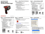
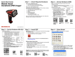
Download HS-2D Handheld Reader User`s Manual
Transcript
HS-2D Handheld Reader
User’s Manual
P/N 83-100002 Rev A
Copyright and Disclaimer
Copyright ©2011
Microscan Systems, Inc.,
1201 S.W. 7th Street, Renton, WA, U.S.A. 98057
(425) 226-5700 FAX: (425) 226-8682
ISO 9001 Certified
Issued by TüV USA
All rights reserved. The information contained herein is proprietary and is provided solely for the purpose
of allowing customers to operate and/or service Microscan manufactured equipment and is not to be
released, reproduced, or used for any other purpose without written permission of Microscan.
Throughout this manual, trademarked names might be used. We state herein that we are using the names
to the benefit of the trademark owner, with no intention of infringement.
Windows® Operating System is a registered trademark of Microsoft Corporation.
Disclaimer
The information and specifications described in this manual are subject to change without notice.
Latest Manual Version
For the latest version of this manual, see the Download Center on our web site at:
www.microscan.com.
Technical Support
For technical support, email: [email protected].
Microscan Systems, Inc.
Renton Headquarters
1201 S.W. 7th St.
Renton, WA 98057-1213
USA
Tel: 425.226.5700 / 800.762.1149
Fax: 425.226.8250
Nashua Office
486 Amherst St.
Nashua, NH 03063
USA
Tel: 603.598.8400
Fax: 603.577.5947
Microscan Europe
Tel: 011 31 172 423360
Fax: 011 31 172 423366
Microscan Asia Pacific
Tel: 65 6846 1214
Fax: 65 6846 4641
ii
HS-2D Handheld Reader User’s Manual
Introduction
Microscan Limited Warranty Statement and Exclusions
What Is Covered?
Microscan Systems Inc. warrants to the original purchaser that products manufactured by it will be free
from defects in material and workmanship under normal use and service for a period of one year from the
date of shipment. This warranty is specifically limited to, at Microscan’s sole option, repair or replacement
with a functionally equivalent unit and return without charge for service or return freight.
What Is Excluded?
This limited warranty specifically excludes the following: (1) Any products or parts that have been subject
to misuse, neglect, accident, unauthorized repair, improper installation, or abnormal conditions or operations;
(2) Any products or parts that have been transferred by the original purchaser; (3) Customer misadjustment
of settings contrary to the procedure described in the Microscan Systems Inc. owners manual; (4) Upgrading
software versions at customer request unless required to meet specifications in effect at the time of purchase;
(5) Units returned and found to have no failure will be excluded; (6) Claims for damage in transit are to be
directed to the freight carrier upon receipt. Any use of the product is at purchaser’s own risk. This limited
warranty is the only warranty provided by Microscan Systems Inc. regarding the product. Except for the
limited warranty above, the product is provided “as is.” To the maximum extent permitted by law, this
express warranty excludes all other warranties, express or implied, including but not limited to, implied
warranties of merchantability and. Technical support questions may be directed to: [email protected].
Register your product with Microscan: www.microscan.com/register. Microscan Systems Inc. does not
warrant that the functions contained in the product will meet any requirements or needs purchaser may
have, or that the product will operate error free, or in an uninterrupted fashion, or that any defects or errors
in the product will be corrected, or that the product is compatible with any particular machinery.
Limitation of Liability
In no event shall Microscan Systems Inc. be liable to you or any third party for any special, incidental, or
consequential damages (including, without limitation, indirect, special, punitive, or exemplary damages for
loss of business, loss of profits, business interruption, or loss of business information), whether in contract,
tort, or otherwise, even if Microscan Systems Inc. has been advised of the possibility of such damages.
Microscan Systems Inc.’s aggregate liability with respect to its obligations under this warranty or otherwise
with respect to the product and documentation or otherwise shall not exceed the amount paid by you for
the product and documentation. Some jurisdictions do not allow the exclusion or limitation of incidental or
consequential damages or limitations on an implied warranty, so the above limitation or exclusion may not
apply to you. This warranty gives you specific legal rights, and you may also have other rights which may
vary from state to state.
Tel: 425.226.5700 | Fax: 425.226.8250 | [email protected]
HS-2D Handheld Reader User’s Manual
iii
Table of Contents
Table of Contents
Chapter 1
Quick Start
Check Required Hardware ...................................................................... 1-2
USB Interface .......................................................................................... 1-3
RS-232 Interface ..................................................................................... 1-4
Install ESP............................................................................................... 1-5
Select Model............................................................................................ 1-6
Select Protocol and Connect to Imager................................................... 1-7
Chapter 2
Using ESP
EZ Mode .................................................................................................. 2-2
Application Mode ..................................................................................... 2-3
Tree Controls........................................................................................... 2-4
Menu Toolbar .......................................................................................... 2-5
Send/Receive ....................................................................................... 2-14
Chapter 3
Basic Operations
Practice Targeting ................................................................................... 3-2
Determine Optimum Position .................................................................. 3-3
Chapter 4
Communications
Communications by ESP......................................................................... 4-2
Communications Overview...................................................................... 4-3
USB Interface .......................................................................................... 4-4
RS-232 Interface ..................................................................................... 4-5
Preamble ................................................................................................. 4-7
Postamble ............................................................................................... 4-8
Preamble and Postamble by ESP ........................................................... 4-9
Keyboard Mapping ................................................................................ 4-10
Text Commands .................................................................................... 4-11
Other Communications Settings in ESP................................................ 4-12
Chapter 5
Symbologies
Symbologies by ESP............................................................................... 5-2
Aztec ....................................................................................................... 5-3
Codabar................................................................................................... 5-4
Codablock A / Codablock F ..................................................................... 5-5
Code 11 ................................................................................................... 5-6
Code 39 ................................................................................................... 5-7
Code 93 ................................................................................................... 5-9
Code 128 ............................................................................................... 5-10
Composite ............................................................................................. 5-11
Data Matrix ............................................................................................ 5-12
Interleaved 2 of 5................................................................................... 5-13
Maxicode ............................................................................................... 5-14
Matrix 2 of 5........................................................................................... 5-15
MicroPDF417 ........................................................................................ 5-16
iv
HS-2D Handheld Reader User’s Manual
Introduction
MSI Plessey........................................................................................... 5-17
NEC 2 of 5 ............................................................................................. 5-18
PDF417 ................................................................................................. 5-19
Pharmacode .......................................................................................... 5-20
QR Code................................................................................................ 5-22
GS1 DataBar ......................................................................................... 5-23
UPC/EAN/JAN ....................................................................................... 5-24
Symbology Identifier .............................................................................. 5-25
Chapter 6
I/O Parameters
I/O Parameters by ESP ........................................................................... 6-2
HS-2D Operational Feedback ................................................................. 6-3
Automatic Gain Control (AGC) ................................................................ 6-4
Image Quality .......................................................................................... 6-5
Chapter 7
Advanced Operations
Continuous Operations............................................................................ 7-2
Lock Settings ........................................................................................... 7-3
Button Stay-Down Time........................................................................... 7-4
Mirroring .................................................................................................. 7-5
Motion Detection...................................................................................... 7-6
Chapter 8
Terminal
Terminal View.......................................................................................... 8-2
Find.......................................................................................................... 8-3
Send ........................................................................................................ 8-4
Macros..................................................................................................... 8-5
Terminal Right-Click Menu ...................................................................... 8-6
Terminal Dropdown Menu ....................................................................... 8-7
Chapter 9
Utilities
Device Control ......................................................................................... 9-2
Differences from Default .......................................................................... 9-3
Firmware.................................................................................................. 9-4
Advanced................................................................................................. 9-6
Appendices
Appendix A General Specifications .........................................................A-2
Appendix B Electrical Specifications .......................................................A-4
Appendix C HS-2D Maintenance.............................................................A-7
HS-2D Handheld Reader User’s Manual
v
About the HS-2D Handheld Reader
About the HS-2D Handheld Reader
The HS-2D Handheld Reader, with point-and-click triggering, can read both 1D and 2D
symbols and transfer (or buffer and transfer later) decoded data. The HS-2D Handheld
Reader is available in USB and RS-232 cabled options.
The HS-2D features a 1.3 million pixel CMOS sensor, and a 400 MHz processor. The
imager automatically discriminates between all major 1D and 2D symbologies.
The HS-2D Handheld Reader can be configured by reading Data Matrix symbols encoded
with a wide variety of setup commands, or by using Microscan’s ESP® Software.
About This Manual
This manual provides complete information on setting up, installing, and configuring the
HS-2D Handheld Reader. The chapters are presented in the order in which the imager
would be assembled, configured, and optimized.
Highlighting
Cross-references and web addresses are highlighted in blue bold.
References to ESP, its toolbar headings (Communications, Symbologies, I/O Parameters,
etc.) and menu headings are highlighted in Bold Initial Caps.
vi
HS-2D Handheld Reader User’s Manual
Introduction
Statement of Agency Compliance
The HS-2D has been tested for compliance with FCC regulations and was found to be
compliant with all applicable FCC Rules and Regulations.
IMPORTANT NOTE: To comply with FCC RF exposure compliance requirements, this
device must not be co-located or operate in conjunction with any other antenna or transmitter.
CAUTION: Changes or modifications not expressly approved by the party responsible for
compliance could void the user’s authority to operate the equipment.
The HS-2D has been tested for compliance to CE (Conformité Européenne) standards
and guidelines and was found to conform to applicable CE standards, specifically the EMC
requirements EN 55024, ESD EN 61000-4-2, Radiated RF Immunity EN 61000-4-3, ENV
50204, EFT EN 61000-4-4, Conducted RF Immunity EN 61000-4-6, EN 55022, Class B
Radiated Emissions, and Class B Conducted Emissions.
HS-2D Handheld Reader User’s Manual
vii
Statement of RoHS Compliance
Statement of RoHS Compliance
All Microscan readers are RoHS-Compliant. All compliant readers were converted prior to
March 1, 2007. All standard accessories in the Microscan Product Pricing Catalog are
RoHS-Compliant except 20-500013-01 and 98-000039-02. These products meet all the
requirements of the European Parliament and the Council of the European Union for
RoHS compliance. In accordance with the latest requirements, our RoHS-compliant products and packaging do not contain intentionally added Deca-BDE, Perfluorooctanes
(PFOS) or Perfluorooctanoic Acid (PFOA) compounds above the maximum trace levels. To
view the documents stating these requirements, please visit:
http://eur-lex.europa.eu/LexUriServ/LexUriServ.do?uri=CELEX:32002L0095:EN:HTML
and
http://eur-lex.europa.eu/LexUriServ/LexUriServ.do?uri=OJ:L:2006:372:0032:0034:EN:PDF
Please contact your sales manager for a complete list of Microscan’s RoHS-Compliant products.
This declaration is based upon information obtained from sources which Microscan believes to be reliable, and
from random sample testing; however, the information is provided without any representation of warranty,
expressed or implied, regarding accuracy or correctness. Microscan does not specifically run any analysis on our
raw materials or end product to measure for these substances.
The information provided in this certification notice is correct to the best of Microscan’s knowledge at the date of
publication. This notice is not to be considered a warranty or quality specification. Users are responsible for
determining the applicability of any RoHS legislation or regulations based on their individual use of the product.
viii
HS-2D Handheld Reader User’s Manual
1 Quick Start
Contents
Check Required Hardware ........................................................................................................... 1-2
USB Interface ............................................................................................................................... 1-3
RS-232 Interface .......................................................................................................................... 1-4
Install ESP .................................................................................................................................... 1-5
Select Model................................................................................................................................. 1-6
Select Protocol and Connect to Reader ....................................................................................... 1-7
This section is designed to get your HS-2D Handheld Reader up and running quickly so
you can get a sense of its capabilities and test sample symbols. Detailed setup information
for configuring the reader for your specific application can be obtained in the subsequent
sections.
Your interface type will determine how data is received by your host. When sending data by
USB, you must open a text editor in your host computer. When sending data serially, you
must use a terminal program such as HyperTerminal or ESP’s Terminal view (RS-232 only).
HS-2D Handheld Reader User’s Manual
1-1
Check Required Hardware
Check Required Hardware
Parts List for USB HS-2D Handheld Reader:
• One HS-2D Handheld Reader
• One 6 ft. USB cable (pre-attached to reader)
Parts List for RS-232 HS-2D Handheld Reader:
• One HS-2D Handheld Reader
• Cable clip attachment
• Spacer
• Two threaded screws
• 8 ft. coiled R-232 cable
• Power supply
1-2
HS-2D Handheld Reader User’s Manual
Quick Start
USB Interface
Note: The USB interface draws its power from the host computer.
USB Configuration
Item
1
2
Description
HS-2D Handheld Reader
USB Cable
Part Number
98-000107-01
Included
Installation Steps for USB
1. Connect the USB cable to the HS-2D.
2. Connect the USB cable to the host.
You do not need to power off your host
computer.
3. Open any program in your host computer
that can receive keyboard text.
4. Read the Reset to USB Factory
Defaults symbol below:
Reset to USB
Factory Defaults
USB Configuration
5. Read the Save Settings symbol.
Save
Settings
Test Symbol
(ABCDEFGHIJKLMNOP)
HS-2D Handheld Reader User’s Manual
1-3
RS-232 Interface
RS-232 Interface
Note: Unlike USB, the RS-232 interface does not draw its power from the host computer.
RS-232 Configuration
Item
1
3
Description
HS-2D Handheld Reader
RS-232 Interface Kit (USA)
RS-232 Interface Kit (Europe)
RS-232 Interface Kit (UK)
Part Number
98-000107-01
98-000074-04
98-000074-05
98-000074-06
Installation Steps for RS-232
1. Power-off the host computer.
2. Connect the 8-pin mini-DIN on the
cable to the HS-2D.
3. Connect the 9-pin D-sub connector to
the host computer’s serial port.
4. Connect the cable to the power supply.
5. Plug in the power supply and power-on
the host computer.
6. Start up a terminal program (such as
ESP’s Terminal view or HyperTerminal)
and set to 57.6K baud, 8 data bits,
none parity, and 2 stop bits.
7. Read the Reset to RS-232 Factory
Defaults symbol below.
RS-232 Configuration
Reset to RS-232
Factory Defaults
8. Read the Save Settings symbol.
Save
Settings
Test Symbol
(ABCDEFGHIJKLMNOP)
1-4
HS-2D Handheld Reader User’s Manual
Quick Start
Install ESP
ESP Software can be found on the Microscan Tools CD that is packaged with the HS-2D.
1. Follow the prompts to install ESP from the CD.
2. Click on the ESP icon to run the program.
Note: ESP can also be installed from the Download Center at www.microscan.com.
ESP System Requirements
•
•
•
•
•
•
166 MHz Pentium processor (Pentium II processor recommended)
Windows Vista, XP, or 2000 operating system
Internet Explorer 5.0 or higher
64 MB minimum RAM (128+ MB RAM recommended)
80 MB hard drive space
800 x 600 minimum 256 color display (1024 x 768 32-bit color recommended)
Important: The reader must be in one of the modes below to communicate with ESP.
USB
USB
Connect
Mode
RS-232
RS-232
Connect
Mode
Save
Settings
HS-2D Handheld Reader User’s Manual
1-5
Select Model
Select Model
When you start ESP, the following menu will appear:
If you need to select another model later, click Switch Model at the top of the screen.
1. Click the HS-2D button and then click OK. If you do not want to make this selection
every time you start ESP, uncheck “Show this dialog at startup”.
2. Select the default reader name (HS-2D-1), or type a name of your choice in the
Description text field and click OK.
3. Click Yes when this dialog appears:
1-6
HS-2D Handheld Reader User’s Manual
Quick Start
Select Protocol and Connect to Reader
RS-232
• In the Select Protocol dialog box, select the communications protocol you are using
and click Next.
• Print the RS-232 Connect Mode symbol (also shown in the Install ESP step) and
decode it with the reader to ensure that you are in the correct communications mode.
Keep the printed symbol in a convenient place for future use.
• Click Next when you are finished.
• The Com Port dialog will then reappear. Select which communications port you are
using. If you don’t see your communications port listed on the dropdown menu, select Other.
• Click Connect.
• When you are connected successfully, the CONNECTED message will appear in a
green box in the status bar at the bottom right of the screen.
If the connection attempt fails, enable a different communications port, check your port
connections, and try again.
You are now ready to configure your reader using ESP. Subsequent sections provide
more detailed information about ESP’s configuration options.
HS-2D Handheld Reader User’s Manual
1-7
Select Protocol and Connect to Reader
USB
• In the Select Protocol dialog box, select the communications protocol you are using
and click Next.
• Print the USB Connect Mode symbol (also shown in the Install ESP step) and decode
it with the reader to ensure that you are in the correct communications mode. Keep the
printed symbol in a convenient place for future use.
• Click Next when you are finished.
The Select Device dialog will then reappear:
Reader ID number should match
the serial number on the base of
the reader.
• You will see a “ Reader” ID number in the Select Device field. Click Connect.
• When you are connected successfully, the CONNECTED message will appear in a
green box in the status bar at the bottom right of the screen.
You are now ready to configure your reader using ESP. Subsequent sections provide
more detailed information about ESP’s configuration options.
1-8
HS-2D Handheld Reader User’s Manual
2 Using ESP
EZ Mode ....................................................................................................................................... 2-2
Application Mode .......................................................................................................................... 2-3
Tree Controls................................................................................................................................ 2-4
Menu Toolbar ............................................................................................................................... 2-5
Send/Receive ............................................................................................................................ 2-14
This section is designed to help you understand the structure and application of ESP.
When you open ESP, unless otherwise specified in the ESP Preferences dialog accessible
from the Options heading on the menu toolbar, you will enter EZ Mode for initial setup.
From there, you can enter Application Mode (App Mode) and access several configuration
menus (Communications, Read Cycle, Symbologies, I/O Parameters, a Terminal
interface, and a Utilities interface).
ESP can be used to configure the HS-2D Handheld Reader in the following ways:
• Tree Controls: Each configuration menu contains a list of all option settings that pertain
to that specific element of reader operation. For example, the Communications menu
shows a Communications Mode command, and then the options RS-232 Serial, USB
Keyboard, and USB Native (HID), all of which are accessible from a dropdown menu.
• Graphic User Interfaces: Settings can be configured using such point-and-click tools
as radio buttons, tabs, spin boxes, check boxes, and drag-and-drop functions.
• Terminal: ESP’s Terminal interface allows you to send configuration and utility commands
directly to the reader by typing them in the provided text field.
HS-2D Handheld Reader User’s Manual
2-1
EZ Mode
EZ Mode
The EZ Mode screen is the first thing you will see when you start ESP. EZ Mode will help
you get your reader up and running quickly, and will acquaint you with the ESP interface.
The EZ Mode toolbar allows you to switch to
App Mode, check your connection parameters,
and to switch models.
The Decode button
allows you to begin
capturing images
and displaying
decoded symbol
data right away.
The Taking Pictures button menu allows you to capture
images that can be displayed in the view below.
When an image is captured, it is displayed
here. Double click this image to view it in a
larger format. Click Save Image to save it
to a location of your choice.
2-2
HS-2D Handheld Reader User’s Manual
Using ESP
Application Mode
Application Mode gives you access to a robust configuration environment, including
tree controls that let you make precise changes to operation parameters, and graphic
interfaces that make configuring your reader easy and intuitive.
Click here to
return to
EZ Mode.
Menu
toolbar
Click on this icon to
return to this view from
Utilities or Terminal.
Click these buttons to
Send and Receive
commands or switch
reader models.
Click here
to open
Terminal.
Click here for Batch
Files and Firmware.
Click these tabs to access
configuration tree controls.
Assign Preamble and Postamble characters
using the simple interface shown above.
Note: For specific information on any of the icons shown above in the operations bar or
configuration bar, see corresponding sections.
HS-2D Handheld Reader User’s Manual
2-3
Tree Controls
Tree Controls
To make changes to configuration settings in the tree control menus:
1. Left click on the +/to expand or collapse the tree.
2. Double click on
the parameter and
click once in the
selection box to
view options.
3. Place your cursor
in the selection
box, scroll down to
the setting you
want to change
and click once on
the setting.
4. Left click again on the open screen to complete the
selection.
5. Right click on the open screen and select Save to
Reader to implement the command in the reader.
The reader must be in one of the modes below to communicate with ESP.
2-4
USB
USB
Connect
Mode
RS-232
RS-232
Connect
Mode
HS-2D Handheld Reader User’s Manual
Using ESP
Menu Toolbar
File > New
Whenever New is selected from the File menu, the default
configuration of ESP is loaded.
Open / Save
When Save or Save As is selected, the ESP configuration is
saved to the host computer’s hard drive and available whenever
the same file is selected under Open.
When you save menu changes to your hard drive, these
changes are not saved to your reader. The diagram below
shows how settings can be saved and received between ESP
and the reader, and ESP and the host hard drive.
(Save to Reader)
(Receive Reader
Settings)
Import / Export
Import converts the ASCII settings from a text file to ESP configuration settings.
Export converts the active ESP configuration settings to an ASCII text file.
HS-2D Handheld Reader User’s Manual
2-5
Menu Toolbar
Model
The Model menu allows you to select between reader
models. When you choose another model, the current
connection with your present model will be terminated.
New Model
To connect to another model, select New Model, choose the model you want, and click OK.
All models you have selected and enabled will continue to appear in the dropdown model
menu. The New Model option is repeated when you click the Switch Model button on the
top row of icons.
2-6
HS-2D Handheld Reader User’s Manual
Using ESP
Options
You can use the Options menu to save memos and set up ESP preferences.
Preferences will be saved and loaded into ESP the next time ESP is opened, whether or
not you save the ESP file to the host computer.
Preferences > General Tab
Reload Last File
At startup, reloads the last file saved to the computer.
Show Model Prompt
At startup, remembers the last connected model and displays it in the Connecting...
dialog whenever you attempt to connect.
Skip EZ Mode
At startup, skips EZ Mode and opens directly in App Mode.
Show Connect Prompt
At startup, displays the Would you like to connect... prompt.
Receive After Connect
At startup, loads the reader’s settings into ESP. (This is not recommended if you want to
preserve your ESP settings for future use.)
Show Both Icon and Text (Default)
Sets the toolbar to display icons and names of all operations.
Only Show Icon
Sets the toolbar to display only icons representing operations, without text.
Only Show Text
Sets the toolbar to display names of operations only, without icons.
HS-2D Handheld Reader User’s Manual
2-7
Menu Toolbar
Terminal Tab
When Show Non-Printable Characters
is checked, characters such as
‘CRLF’ will be displayed in the terminal
window. When the Enhanced Format
radio button is checked, subscript and
superscript formatting is shown.
When Display incoming data even
when not in focus is checked, data
from the reader will continue to
appear in the terminal even when
ESP is not the top window on the host
computer’s screen.
When Enable Echo is checked, the
terminal window displays user-entered
data.
Change Keyboard Macros
Clicking the Change Keyboard Macros
button brings up the Function Keys
dialog. In this dialog you can select the
desired function key and then enter
your macro keystrokes in the associated
key map. For example, to make Ctrl-F2
the keystroke to send a trigger character,
select F2, then in the Ctrl row, enter
<trigger character> and click OK.
Then whenever the Ctrl-F2 keystroke is
pressed, the trigger character will start
the read cycle.
Note: The F1 key is reserved for opening ESP Help and the F3 key is reserved for the
Find Next function.
Change Font
Sets the font characteristics for data received from the reader.
Change Echo Font
Sets the font characteristics of user-entered data.
2-8
HS-2D Handheld Reader User’s Manual
Using ESP
Bar Code Options Tab
Sizing Information
Sets element size (in thousands of an inch) of symbols that you create and print from the
Bar Code Dialog under View.
HS-2D Handheld Reader User’s Manual
2-9
Menu Toolbar
Advanced Tab
The Auto Sync dialog on the Advanced tab allows you to determine whether Auto Sync
will be automatically enabled in sections of ESP where it is used, or if it will ask you before
it enables Auto Sync functions.
Always Ask Before Auto Sync Occurs
If you check this option box, you are then able to determine what specific Auto Sync
functions will be enabled. Receive Settings from the Reader will automatically send
the reader’s settings to ESP when Auto Sync is enabled. Send ESP Settings to the
Reader will automatically send all reader configuration settings chosen in ESP to the
reader. Do Not Send or Receive Settings creates a condition in which Auto Sync will
not send reader settings to ESP, or send ESP settings to the reader.
Send XON with Auto-Connect
Sends an XON (Begin Transmission) command to the reader before starting the Auto-Connect
routine.
2-10
HS-2D Handheld Reader User’s Manual
Using ESP
Document Memo
The information you type in the Document Memo field will appear in a context-sensitive text
box whenever your cursor hovers over the Document Memo item on the Options menu.
Model Memo
Similar to Document Memo, the information you type in the Model Memo field will appear
in a context-sensitive text box whenever your cursor hovers over the Model Memo item on
the Options menu. Memos created in Model Memo are specific to the model enabled
when the message was created.
Note: Memos must be saved in a .esp file if you want them to available in your next session.
If you do not save your current session, any memos that you have entered during the session
will be discarded, and will be unavailable in your next session.
HS-2D Handheld Reader User’s Manual
2-11
Menu Toolbar
Connection Wizard
When you choose to connect to the reader via the Connection Wizard, you will first need
to select the correct protocol (see Select Protocol and Connect to Reader).
When you have successfully connected to the reader you will see one of the two following
displays in the status bar at the lower right of the screen:
RS-232:
USB:
2-12
HS-2D Handheld Reader User’s Manual
Using ESP
View
The options in the View menu correspond to icons on the operations
toolbar (Parameters, Setup, Terminal, Utilities). Each option
allows you to configure the reader or to perform various other
functions in the chosen view.
The View menu also allows you to access the Barcode Dialog.
Bar Code Dialog
In the Bar Code Dialog you can directly type the text and commands you want to encode. This allows you to create configuration
symbols that you can print and read with the reader.
HS-2D Handheld Reader User’s Manual
2-13
Send/Receive
Send/Receive
To access Receive, Save, Default, and Advanced options, click the Send/Recv button.
You can also access these options by right-clicking in any of the configuration views.
Receive Reader Settings
From the Send/Recv menu, select Receive Reader Settings.
This option is useful if you want to receive the reader’s settings and save them as a file for
later retrieval. For example, if your reader has settings that you do not want to change,
choosing Receive Reader Settings will allow you to load those settings to ESP and save
them as an ESP file.
Receiving the reader’s settings also assures that you will not subsequently save any
unwanted configuration changes previously made in ESP.
Select this option if you want to upload the reader’s settings to ESP. For example, if your
ESP file has a number of custom settings that you want to maintain and download to the
reader, you will lose those ESP settings if you choose to receive settings from the reader.
Save to Reader
Send, No Save
This saves ESP settings to current memory.
Send and Save
This activates all changes in current memory and saves to
the reader.
2-14
HS-2D Handheld Reader User’s Manual
Using ESP
Default
When you select Default Current Menu Settings or Default all ESP Settings you are
only defaulting settings in ESP. The reader is not affected unless you download new settings.
Advanced Options
Send Current View
This is the same as Save
to Reader > Send No
Save except that only the
commands in the current
menu tree are sent.
Send Current
Command
This is the same as Send
Current View above, but
only saves the command
that is currently selected.
HS-2D Handheld Reader User’s Manual
2-15
Send/Receive
2-16
HS-2D Handheld Reader User’s Manual
3 Basic Operations
Contents
Practice Targeting ........................................................................................................................ 3-2
Determine Optimum Position........................................................................................................ 3-3
This section explains how to practice targeting and triggering, and how to begin configuring
the reader.
HS-2D Handheld Reader User’s Manual
3-1
Practice Targeting
When first connecting, allow approximately 3 seconds for the reader to initialize.
1. Hold the reader steady and point at a symbol about 2.3
inches (5.8 cm) away.
2. Squeeze and hold the trigger. Red and green targeting
spots will appear in front of the reader.
3. Center the red and green spots on the symbol and wait a
second or two for a decode.
For configuration symbols, you will hear 2 beeps when a
good read occurs. For data symbols, you will hear 1 beep
when a good read occurs.
4. If no decode occurs, slowly draw away from the symbol
while holding the laser spot steadily in place.
Test Symbol
ABCDEFGHIJKLMNOP
Targeting Suggestions
• Typically, you should not hold the reader exactly perpendicular to the symbol. Position
the reader about 15 to 30 degrees to avoid specular reflection.
• Do not wave the reader side-to-side or up-and-down, or attempt to sweep across a
symbol; sudden movements will create fuzzy images and result in failed read attempts.
• The reader is omnidirectional and can read a symbol from any position (The exception
to this is with certain linear symbols; in these cases, the read area will be oriented to the
length of the symbol.)
Targeting LEDs
Read the configuration symbols below to enable or disable red and green targeting LEDs.
Red Targeting
LED On
3-2
Red Targeting
LED Off
Green Targeting
LED On
Green Targeting
LED Off
HS-2D Handheld Reader User’s Manual
Basic Operations
Determine Optimum Position
1. Position the reader in front of the symbol.
• 2.3 inches (5.8 cm).
2. Determine the optimum read position by triggering at different distances and angles.
Smaller symbols require the unit to be held close to the optimal focal distance. For
larger symbols, which have a larger depth of field, refer to the chart below.
Test Symbol
ABCDEFGHIJKLMNOP
HS-2D Handheld Reader User’s Manual
3-3
3-4
HS-2D Handheld Reader User’s Manual
4 Communications
Contents
Communications by ESP.............................................................................................................. 4-2
Communications Overview........................................................................................................... 4-3
USB Interface ............................................................................................................................... 4-4
RS-232 Interface .......................................................................................................................... 4-5
Preamble ...................................................................................................................................... 4-7
Postamble..................................................................................................................................... 4-8
Preamble and Postamble by ESP ................................................................................................ 4-9
Keyboard Mapping .................................................................................................................... 4-10
Text Commands ......................................................................................................................... 4-11
Other Communications Settings in ESP..................................................................................... 4-12
This section includes connection parameters and options for communicating with the
HS-2D Handheld Reader in various interfaces.
HS-2D Handheld Reader User’s Manual
4-1
Communications by ESP
Communications by ESP
To make changes to configuration settings in the Communications tree control:
1. Left click
on the + to
expand the
tree.
2. Double click on the
parameter and click once
in the selection box to
view options.
3. Place your cursor in the
selection box, scroll down
to the setting you want to
change and click once
on the setting.
4-2
4. Left click again on the open screen to complete the
selection.
5. Right click on the open screen and select Save to
Reader to implement the command in the imager.
HS-2D Handheld Reader User’s Manual
Communications
Communications Overview
All HS-2D Handheld Readers are shipped with a USB cable. You can also add RS-232
capabilities and configure your imager accordingly. Whenever you default the imager, it
will return to the default settings of whichever interface you are using. Defaulting the imager
does not remove preamble and postamble formatting.
Note: You must use USB Connect Mode or RS-232 Connect Mode to connect to ESP.
Once the imager is connected to ESP, you can select your communications mode and set
other communication parameters.
USB
With USB communications, the imager connects directly to the host’s USB port from which it
draws its power. Data is displayed by any open Windows-based program that can capture
text in USB Keyboard Mode.
RS-232
With RS-232 communications the imager communicates with the host through a communications
program such as HyperTerminal.
Default settings for establishing RS-232 communications are:
Baud =
Stop Bits =
Data Bits =
Parity =
57.6K
2
8
None
HS-2D Handheld Reader User’s Manual
4-3
USB Interface
USB Interface
USB Keyboard is the default interface in which data is transferred to a Windows-based
text program as keyboard data.
See USB Interface for detailed steps on setting up the USB Interface.
USB Keyboard Mode
Data is entered as keyboard sequences. You need to read this symbol
whenever you are changing from a different interface to USB.
USB Downloader Mode
This mode is the standard way of transferring unformatted, unpacketized
data to the imager through the USB port.
USB Native Two-Way Mode
This mode is used when the user needs error-corrected communication
between the HS-2D and the host the USB port.
USB Virtual COM Mode
This mode allows an HS-2D in a USB configuration to function as a
virtual serial COM port. This mode requires installation of a USB Virtual
COM driver. Contact your Microscan sales representative to request
this driver, as well as installation instructions.
USB HID POS (Terminal ID 131)
This mode allows a USB-cabled HS-2D to communicate as a USB
HID POS (Terminal ID 131) device.
4-4
HS-2D Handheld Reader User’s Manual
Communications
RS-232 Interface
Enabling either of these modes will disable USB communications and require you to
default the imager or read the “USB Keyboard” symbol to return to USB.
See RS-232 Interface for detailed steps on setting up the RS-232 Interface.
RS-232 Default Settings
This mode is the standard way of transferring unformatted, unpacketized data through the
RS-232 port.
You will need to read this symbol whenever you set up RS-232 communications.
Baud Rate (RS-232)
Baud Rate is the rate at which the imager and host transfer data. It only needs to be
changed if necessary to match the host setting.
1200
19.2K
2400
38.4K
4800
57.6K (Default)
9600
115.2K
HS-2D Handheld Reader User’s Manual
Save Settings
4-5
RS-232 Interface
Parity (RS-232)
Parity is an error detection routine in which one data bit in each character is set to 1 or 0
so that the total number of 1 bits in the data field is even or odd. It only needs to be
changed if necessary to match the host setting.
None (Default)
Even
Odd
Stop Bits (RS-232)
Stop Bits are added to indicate the end of each character. This setting should only be
changed if necessary to match the host setting.
2 Stop Bits (Default)
1 Stop Bit
Data Bits (RS-232)
Data Bits are the total number of bits in each character. This setting only needs to be
changed if necessary to match the host setting.
8 Data Bits (Default)
4-6
7 Data Bits
HS-2D Handheld Reader User’s Manual
Communications
Preamble
A preamble is a character or series of characters that is added to the beginning of a
decoded data string. Preamble characters will appear in the order that they are enabled
(left to right). For example, if you enable a comma and then a space, and then decode a
symbol containing the data ‘ABC’, your output will look like this:
, ABC
The only limit to the number of preambles enabled is the total memory size available.
Important: Be sure to save all settings before reading any of the following preamble
symbols—otherwise your settings may be lost.
Save Settings
Set the desired preamble by reading the appropriate symbol below.
Comma
Space
Tab (USB Only)
Important: Use
only with serial
applications.
Tab
Erase All
Preamble Data
Carriage Return
Line Feed
Note: To erase all preamble and postamble data, read the following symbol:
Erase Preamble and Postamble Data
HS-2D Handheld Reader User’s Manual
4-7
Postamble
Postamble
A postamble is a character or series of characters that is added to the end of a decoded
data string. Postamble characters will appear in the order that they are enabled (left to
right). For example, if you enable a space and then a comma, and then decode a symbol
containing the data ‘ABC’, your output will look like this:
ABC
,
The only limit to the number of postambles enabled is the total memory size available.
Important: Be sure to save all settings before reading any of
the following postamble symbols—otherwise your settings may
be lost.
Save Settings
Set the desired postamble by reading the appropriate symbol below.
Important: Use
only with serial
applications.
Important: Use
only with serial
applications.
Carriage Return
Comma
Line Feed
Important: Use
only with USB or
PS/2 Keyboard
modes.
Important: Use
only with serial
applications.
Carriage Return
Line Feed
Space
Enter
Important:
Reading this
symbol will
erase all
postamble
data.
Important: Use
only with USB or
PS/2 Keyboard
modes.
Tab
Tab (RS-232 Only)
Erase / None
Note: To erase
all postamble
and preamble
data, read the
symbol at right:
4-8
Erase Preamble
and Postamble
Data
HS-2D Handheld Reader User’s Manual
Communications
Preamble and Postamble by ESP
Characters can also be added to the beginning and end of data strings using ESP. There
are a few different ways to do this, using the interface shown below.
You will see the Communications tree control on the left, and the Preamble/Postamble
interface on the right.
When you type ASCII characters directly into the Preamble
or Postamble text fields and then click Send to Reader,
those preamble or postamble characters are enabled and
will appear in data output.
Save pre- and postamble
settings and send them to
the reader.
In addition to typing directly
in the text fields and selecting
from the dropdown menu,
you can also click any of
these preset buttons to set a
preamble or postamble.
HS-2D Handheld Reader User’s Manual
Scroll through a list of all preamble
and postamble options, and then
click Insert.
4-9
Keyboard Mapping
Keyboard Mapping
The Keyboard Mapping feature provides alternatives for keyboards that do not conform
to US English mapping.
Note: Universal Keyboard mapping is slightly slower than the other language-specific
options, because it maps data by reference to the full set of ASCII characters. The
advantage of Universal Keyboard mapping is that it allows any language and keyboard
layout to be mapped.
Important: Keyboard Mapping is not to be confused with USB Keyboard Mode, which
has an entirely different function—namely to enable USB cabled communications. (See
USB Interface).
US English, No Leading
0 for non-printable
characters (Default)
US English, Leading
0 for non-printable
characters
French
German
Universal Keyboard
Custom Keyboard
Enable Alternate OS
(Windows CE/MAC/Unix/
Linux)
US English, Ctrl + char. for
non-printable characters
Japanese
Disable Alternate OS
Keyboard Mapping by ESP
4-10
HS-2D Handheld Reader User’s Manual
Communications
Text Commands
When the Text Commands feature is enabled, the HS-2D can accept text commands via
RS-232 connections and USB Virtual COM modes.
Note: Text Commands are not supported in USB HID Mode.
Enable Text Commands
(Default)
Disable Text Commands
Text Commands by ESP
When Magic Sequence is enabled, it allows the user to enable
Text Commands by entering a predetermined series of keystrokes.
When Text Commands are set to
Enabled; Suppress Echo, text
that a user enters in the terminal
will not be shown. When Text
Commands are set to Enabled;
Suppress Echo and Responses,
neither user-entered data or reader
responses will be shown, and only
decoded symbol data will appear in
the terminal.
See Terminal Right-Click Menu
for a way to change Echo settings
directly in the terminal view.
Entering Magic Sequence
The magic sequence is ;>PA followed by a numeric value of 1, 3, or 7.
1 = Enable Text Commands
3 = Enabled; Suppress Echo
7 = Enabled; Suppress Echo and Responses
In the example below, the magic sequence entered will Enable Text Commands and
Suppress Echo and Responses.
Enter the magic sequence in
this text field and click Send.
Once the magic sequence has been sent, you can send text commands from the same text field.
HS-2D Handheld Reader User’s Manual
4-11
Other Communications Settings in ESP
Other Communications Settings in ESP
Some ESP Communications options are unique to the software, and do not have corresponding
programming symbols. These options are explained below.
Reader Packet Format
Data that is sent from the imager to the host in Raw format is sent without packet framing
or check characters. One-Way communication is in a raw format, no response is expected
from the host, and data is not resent.
Packetized data is sent with framing (a preamble communicating the amount of data to be
transmitted, and a postamble containing error detection) and check characters, and a
response is expected from the host. Two-Way communication is in packet format.
Reader to Host Packet Size
The Reader to Host Packet Size is the amount of data (in bytes) that is sent to the host in
packet format. This feature allows you to set the maximum allowable packet size.
Expect Host Response
When Expect Host Response is enabled, the imager will re-transmit data if it doesn’t
receive acknowledgement from the host.
Reader Send Retry Count
Reader Send Retry Count sets the number of times the imager will re-transmit data
before abandoning further send attempts. The minimum retry count is 1, which represents
the initial transmission.
Host Acknowledgement Timeout
The Host Acknowledgement Timeout is the amount of time (in seconds) that the imager
will wait for an acknowledgement from the host before re-sending data.
4-12
HS-2D Handheld Reader User’s Manual
Communications
USB Keyboard Rate
Requests that the host polls the USB HS-2D at the rate specified (1 to 255 ms).
HS-2D Handheld Reader User’s Manual
4-13
Other Communications Settings in ESP
4-14
HS-2D Handheld Reader User’s Manual
5 Symbologies
Contents
Symbologies by ESP .................................................................................................................... 5-2
Aztec............................................................................................................................................. 5-3
Codabar........................................................................................................................................ 5-4
Codablock A / Codablock F .......................................................................................................... 5-5
Code 11 ........................................................................................................................................ 5-6
Code 39 ........................................................................................................................................ 5-7
Code 93 ........................................................................................................................................ 5-9
Code 128 .................................................................................................................................... 5-10
Composite .................................................................................................................................. 5-11
Data Matrix ................................................................................................................................. 5-12
Interleaved 2 of 5........................................................................................................................ 5-13
Maxicode .................................................................................................................................... 5-14
Matrix 2 of 5................................................................................................................................ 5-15
MicroPDF417.............................................................................................................................. 5-16
MSI Plessey................................................................................................................................ 5-17
NEC 2 of 5 .................................................................................................................................. 5-18
PDF417 ...................................................................................................................................... 5-19
Pharmacode ............................................................................................................................... 5-20
QR Code..................................................................................................................................... 5-22
GS1 DataBar .............................................................................................................................. 5-23
UPC/EAN/JAN............................................................................................................................ 5-24
Symbology Identifier ................................................................................................................... 5-25
This section describes the various symbol types that can be read and decoded by the reader.
See http://www.aimglobal.org/standards/aimpubs.asp for additional information.
HS-2D Handheld Reader User’s Manual
5-1
Symbologies by ESP
Symbologies by ESP
To make changes to configuration settings in the Symbologies tree control:
1. Left click on the +
to expand the tree.
2. Double click on the
parameter and click once
in the selection box to view
options.
3. Place your cursor in the
selection box, scroll down
to the setting you want to
change and click once on
the setting.
5-2
4. Left click again on the open screen to complete
the selection.
5. Right click on the open screen and select Save to
Reader to implement the command in the reader.
HS-2D Handheld Reader User’s Manual
Symbologies
Aztec
Read the following symbols to enable/disable Aztec settings:
Aztec On
Aztec Off (Default)
Aztec by ESP
Sample Aztec Symbol
HS-2D Handheld Reader User’s Manual
5-3
Codabar
Codabar
Read the following symbols to enable/disable Codabar settings:
Codabar On (Default)
Codabar Off
Codabar by ESP
ESP allows you to enable
a checksum, or to enable
a check sum and remove
it from the decode result.
Sample Codabar Symbol
5-4
HS-2D Handheld Reader User’s Manual
Symbologies
Codablock A / Codablock F
Read the following symbols to enable/disable Codablock A and Codablock F settings:
Codablock A On
Codablock A Off (Default)
Codablock F On
Codablock F Off (Default)
Codablock by ESP
Important: When Codablock F and Code 128 are both enabled, there is some risk of
mistakenly decoding a damaged Codablock F symbol as a Code 128 symbol. Therefore,
whenever possible, Code 128 should be disabled when Codablock F is enabled.
Using Codablock F On will disable Code 128. Using Codablock F Off will re-enable
Code 128.
Sample Codablock F Symbol
HS-2D Handheld Reader User’s Manual
5-5
Code 11
Code 11
Read the following symbols to enable/disable Code 11 settings:
Code 11 Enabled with 2
Checksum Digits
Code 11 Disabled
(Default)
Enabled with 1 Checksum
Digit
Enabled with 2 Checksum Digits
and Stripped from Result
Enabled with 1 Checksum Digit
and Stripped from Result
Code 11 by ESP
Note: “No Report” in ESP has the same meaning as “Stripped from Result”.
Sample Code 11 Symbol
5-6
HS-2D Handheld Reader User’s Manual
Symbologies
Code 39
Read the following symbols to enable/disable Code 39 settings:
Code 39 On (Default)
Code 39 Off
Enable Checksum
Disable Checksum (Default)
Enable Checksum and Strip from Result
Code 39 Extended
Full ASCII On
Code 39 Extended
Full ASCII Off (Default)
Code 39 Narrow Margins On
Code 39 Narrow Margins Off (Default)
Code 39 Trioptic On (Default)
Code 39 Trioptic Off
HS-2D Handheld Reader User’s Manual
5-7
Code 39
Code 39 by ESP
Sample Code 39 Symbol
Sample Code 39 Trioptic Symbol
5-8
HS-2D Handheld Reader User’s Manual
Symbologies
Code 93
Read the following symbols to enable/disable Code 93 settings:
Code 93 On (Default)
Code 93 Off
Code 93 by ESP
Sample Code 93 Symbol
HS-2D Handheld Reader User’s Manual
5-9
Code 128
Code 128
Read the following symbols to enable/disable Code 128 settings:
Code 128 On (Default)
Code 128 Off
Code 128 Narrow Margins On
Code 128 Narrow Margins Off (Default)
Code 128 by ESP
Sample Code 128 Symbol
5-10
HS-2D Handheld Reader User’s Manual
Symbologies
Composite
To read Composite symbols:
1. Enable the corresponding linear component.
2. Read the Composite On symbol below.
3. Set Maximum Decodes per Read to 2.
Important: Both the applicable linear symbology portion of the Composite symbol as well
as Composite On must be enabled before the reader can fully decode a Composite symbol.
Composite On
Composite Off (Default)
Composite by ESP
Composite Linkage Control
When Composite Linkage Control is set to Required, symbol data will only be output
if both the 2D and 1D components of the symbol are decoded. When not required, symbol
data will be output even when only one of the components is decoded.
Maximum Decodes per Read
Maximum Decodes per Read represents the maximum number of candidate symbols
in the field of view that can be decoded during a read cycle. Note that decode speed will
decrease as the Maximum Decodes per Read value is increased.
HS-2D Handheld Reader User’s Manual
5-11
Data Matrix
Data Matrix
Read the following symbols to enable/disable Data Matrix settings:
Data Matrix
Rectangle On
Data Matrix
Rectangle Off
(Default)
Data Matrix
Inverse On
Data Matrix
Inverse Off
(Default)
Enable Data Matrix Improvements
(Low Contrast and Binarized Symbols)
Disable Data Matrix Improvements (Default)
Sample Data Matrix Symbol
Sample Rectangular Data Matrix Symbol
Data Matrix by ESP
5-12
HS-2D Handheld Reader User’s Manual
Symbologies
Interleaved 2 of 5
Read the following symbols to enable/disable Interleaved 2 of 5 settings:
Interleaved 2 of 5 On (Default)
Interleaved 2 of 5 Off
Interleaved 2 of 5 Two Digits On
Interleaved 2 of 5 Two Digits Off
Interleaved 2 of 5 Four Digits On
Interleaved 2 of 5 Four Digits Off
Interleaved 2 of 5 by ESP
Sample Interleaved 2 of 5 Symbol
HS-2D Handheld Reader User’s Manual
5-13
Maxicode
Maxicode
Read the following symbols to enable/disable Maxicode settings:
Maxicode On
Maxicode Off (Default)
Maxicode by ESP
Mode 0 = Reserved
Mode 1 = Reserved
Mode 2 = US Carrier with postal symbols up to 9 digits in
length.
Mode 3 = International Carrier with alphanumeric postal
symbols up to 6 characters in length.
Mode 4 = Standard Symbol – Use this mode to encode
information for purposes other than the shipping industry.
Up to approximately 90 characters can be encoded in this
mode.
Mode 5 = Secure Symbol – Use this option to encode
information with additional error correction. Up to approximately
74 characters can be encoded in this mode.
Mode 6 = Reader Program – This option allows scanner
manufacturers to program their scanners.
Sample Maxicode Symbol
5-14
HS-2D Handheld Reader User’s Manual
Symbologies
Matrix 2 of 5
Read the following symbols to enable/disable Matrix 2 of 5 settings:
Matrix 2 of 5 On (Default)
Matrix 2 of 5 Off
Matrix 2 of 5 by ESP
Sample Matrix 2 of 5 Symbol
HS-2D Handheld Reader User’s Manual
5-15
MicroPDF417
MicroPDF417
Read the following symbols to enable/disable MicroPDF417 settings:
MicroPDF417 On
MicroPDF417 Off (Default)
MicroPDF417 by ESP
Sample MicroPDF417 Symbol
5-16
HS-2D Handheld Reader User’s Manual
Symbologies
MSI Plessey
Read the following symbols to enable/disable MSI Plessey settings:
MSI Plessey On
MSI Plessey Off (Default)
MSI Plessey by ESP
Sample MSI Plessey Symbol
HS-2D Handheld Reader User’s Manual
5-17
NEC 2 of 5
NEC 2 of 5
Read the following symbols to enable/disable NEC 2 of 5 settings:
NEC 2 of 5 On (Default)
NEC 2 of 5 Off
NEC 2 of 5 by ESP
Sample NEC 2 of 5 Symbol
5-18
HS-2D Handheld Reader User’s Manual
Symbologies
PDF417
Read the following symbols to enable/disable PDF417 settings:
PDF417 On (Default)
PDF417 Off
MacroPDF417 On
MacroPDF417 Off (Default)
PDF417 by ESP
Sample PDF417 Symbol
HS-2D Handheld Reader User’s Manual
5-19
Pharmacode
Pharmacode
Read the following symbols to configure Pharmacode settings:
Pharmacode On;
No Color, Standard Rules, Horizontal Decode, Normal Direction
Pharmacode On;
Color, Relaxed Contrast, Horizontal Decode, Normal Direction
Pharmacode On;
No Color, Standard Rules, Vertical Decode, Normal Direction
Pharmacode On;
Color, Relaxed Contrast, Vertical Decode, Normal Direction
Pharmacode On;
No Color, Standard Rules, Horizontal Decode, Reverse Direction
5-20
HS-2D Handheld Reader User’s Manual
Symbologies
Pharmacode (cont.)
Pharmacode On;
Color, Relaxed Contrast, Horizontal Decode, Reverse Direction
Pharmacode On;
No Color, Standard Rules, Vertical Decode, Reverse Direction
Pharmacode On;
Color, Relaxed Contrast, Vertical Decode, Reverse Direction
Pharmacode Off (Default)
Pharmacode by ESP
Sample Pharmacode Symbol
HS-2D Handheld Reader User’s Manual
5-21
QR Code
QR Code
Read the following symbols to enable/disable QR Code settings:
Standard QR Code On
QR Code Off (Default)
Inverse On
Inverse and Standard On
All QR Code On
Inverse and Micro QR On
QR Code by ESP
Sample QR Code Symbol
Sample Micro QR Code Symbol
5-22
HS-2D Handheld Reader User’s Manual
Symbologies
GS1 DataBar
Read the following symbols to enable/disable DataBar settings:
DataBar Limited On
DataBar-14 and DataBar-14 Truncated On
DataBar-14 Stacked On
DataBar Expanded On
All DataBar On
All DataBar Off (Default)
GS1 DataBar by ESP
Sample DataBar-14 Truncated Symbol
Sample DataBar-14 Stacked Symbol
Sample DataBar Expanded Symbol
Sample DataBar-14 Symbol
HS-2D Handheld Reader User’s Manual
5-23
UPC/EAN/JAN
UPC/EAN/JAN
Read the following symbols to enable/disable UPC/EAN/JAN settings:
UPC On (Default)
UPC Off
UPC Narrow Margins On
UPC Narrow Margins Off (Default)
Note: Unless necessary, enabling Narrow Margins are not recommended.
UPC Extension On
UPC Extension Off (Default)
UPC/EAN/JAN by ESP
Sample UPC-E Symbol
5-24
HS-2D Handheld Reader User’s Manual
Symbologies
Symbology Identifier
When Symbology Identifier is enabled, an AIM (Association for Automatic Identification
and Mobility) preamble is added to decoded data output (see AIM Symbology Identifiers).
This preamble identifies what kind of symbology has been decoded.
Symbology Identifier On
Symbology Identifier Off (Default)
Symbology Identifier by ESP
HS-2D Handheld Reader User’s Manual
5-25
Symbology Identifier
AIM Symbology Identifiers
A
Code 39
B
Telepen
C
Code 128
d
Data Matrix
e
GS1 DataBar
E
UPC/EAN
F
Codabar
G
Code 93
H
Code 11
I
Interleaved 2 of 5
L
PDF417
M
MSI Code
O
Codablock
p
Pharmacode
P
Plessey Code
Q
QR Code / Micro QR Code
X
Other Symbology
z
Aztec
Z
Non-Barcode Data
Modifier Characters
Modifier characters are determined by adding the option values of each symbology. If the
sum is larger than 9, use A, B, C, D, E, or F in place of 10, 11, 12, 13, 14, and 15.
Code 39 Option Values
0
No check character or full ASCII
1
Reader has performed mod 43 check
2
Reader has performed mod 43 check and stipped the check character
4
Reader has performed full ASCII conversion
Telepen Option Values
5-26
0
Full ASCII mode
1
Double-density numeric mode
2
Double-density numeric followed by full ASCII
4
Full ASCII followed by double-density numeric
HS-2D Handheld Reader User’s Manual
Symbologies
Code 128 Option Values
0
Standard
1
Function code 1 in first character position
2
Function code 2 in second character position. Concatenation according to ISBT.
4
Specification has been performed and concatenated data follows.
HS-2D Handheld Reader User’s Manual
5-27
Symbology Identifier
5-28
HS-2D Handheld Reader User’s Manual
6 I/O Parameters
Contents
I/O Parameters by ESP.................................................................................................................6-2
HS-2D Operational Feedback .......................................................................................................6-3
Automatic Gain Control (AGC)......................................................................................................6-4
Image Quality ................................................................................................................................6-5
This section contains information on how to set your reader to the most efficient and
effective parameters for your application.
HS-2D Handheld Reader User’s Manual
6-1
I/O Parameters by ESP
I/O Parameters by ESP
To make changes to configuration settings in the I/O Parameters menu tree control:
1. Left click on the + to expand the tree.
2. Double click on the parameter
and click once in the selection box
to view options.
3. Place your cursor in the selection
box, scroll down to the setting you
want to change and click once on
the setting.
6-2
4. Left click again on the open screen to
complete the selection.
5. Right click on the open screen and
select Save to Reader to implement
the command in the reader.
HS-2D Handheld Reader User’s Manual
I/O Parameters
HS-2D Operational Feedback
Sound/Vibration
Condition
Successful Power-On
1 Beep / Vibration
Successful Connection with Host via USB
Successful Decode and Data Transfer to Host
1 Beep / Vibration
1 Beep / Vibration
2 Beeps / Vibrations
separated by short
pause
Configuration Symbol Successfully Decoded
and Processed
LED
Sequence: AMBER
GREEN AMBER
None
Flash GREEN
Flash GREEN
Beep and Vibration Modes
Read the following symbols to set beep and vibration modes.
Vibrate On /
Beep On
(Default)
Vibrate On /
Beep Off
HS-2D Handheld Reader User’s Manual
Vibrate Off /
Beep On
6-3
Automatic Gain Control (AGC)
Automatic Gain Control (AGC)
AGC is a system that controls gain in order to maintain high performance over a range of
input levels. Gain is essentially the ratio of output to input. Gain settings affect how the
HS-2D decodes symbols and captures images.
AGC Frame Adjust Count
AGC Frame Adjust Count sets the number of image frames captured and discarded
before the main image capture. This feature gives the gain control time to adjust.
6-4
HS-2D Handheld Reader User’s Manual
I/O Parameters
Image Quality
Image Quality allows the user to adjust the quality and size of images captured by the
reader.
1 represents the lowest possibly image quality and size, and 75 represents the highest
possible image quality and size.
HS-2D Handheld Reader User’s Manual
6-5
Image Quality
6-6
HS-2D Handheld Reader User’s Manual
7 Advanced Operations
Contents
Continuous Operations................................................................................................................. 7-2
Lock Settings ................................................................................................................................ 7-3
Button Stay-Down Time................................................................................................................ 7-4
Mirroring ....................................................................................................................................... 7-5
Motion Detection........................................................................................................................... 7-6
This section introduces several settings that can be applied to speed up processing or
improve readablility in various circumstances.
HS-2D Handheld Reader User’s Manual
7-1
Continuous Operations
Continuous Operations
Continuous Read
Read the following symbols to enable or disable Continuous Read.
Continuous Read Off
Continuous Read On
Continuous Read, Trigger Delays
Read the following symbols to set the delay time between decodes.
0 Seconds
(Default)
1 Second
3 Seconds
Continuous Read, Duplicate Read Delays
Read the following symbols to determine the time interval between a decode and the
rejection of a subsequent duplicate decode.
0 Seconds
(Default)
7-2
1 Second
3 Seconds
HS-2D Handheld Reader User’s Manual
Advanced Operations
Lock Settings
Read the symbols below to lock or unlock reader settings.
Note: This feature does not lock preamble and postamble programming symbols, Clear
XML Rules, or postamble erase/none commands.
Lock Reader
Settings
Unlock Reader
Settings
HS-2D Handheld Reader User’s Manual
7-3
Button Stay-Down Time
Button Stay-Down Time
Button Stay-Down Time sets the amount of time (in seconds) that the reader will continue
to process the current “decode symbol” event. The reader will behave as if the trigger is
being activated for this specified amount of time.
Available Button Stay-Down Time
values are 0.000 to 2147483.750
(in seconds).
7-4
HS-2D Handheld Reader User’s Manual
Advanced Operations
Mirroring
Mirroring allows the HS-2D to decode symbols that are reversed. When Mirroring is
enabled, all other decode functionality is disabled.
Note: Once the reader has been set to Mirroring On, it can only return to its default mode
by reading the Mirroring Off symbol below.
Mirroring On
Mirroring Off (Default)
Image Transform
In ESP, the Mirroring feature is part of the Image Transform command.
When Image Transform is set to Standard, Mirrored Image is disabled.
When Image Transform is set to Mirrored Image, the HS-2D’s optics reverse the captured
image before attempting to decode.
HS-2D Handheld Reader User’s Manual
7-5
Motion Detection
Motion Detection
Motion Detection causes the HS-2D to attempt a decode whenever it senses motion in
its field of view.
Motion Detection On
Motion Detection Off (Default)
Motion Detection by ESP
Motion Detection settings can be refined further using the options in ESP.
Select the action you want
the HS-2D to perform
when it detects motion in
the field of view.
Motion Sensitivity
The HS-2D’s sensitivity to motion in the field of view can be configured as shown below.
Note: The lower the number, the greater the sensitivity.
Note: For Motion Sensitivity to function correctly, Button Stay-Down Time should be
increased.
7-6
HS-2D Handheld Reader User’s Manual
8 Terminal
Contents
Terminal View................................................................................................................................8-2
Find ...............................................................................................................................................8-3
Send ..............................................................................................................................................8-4
Macros...........................................................................................................................................8-5
Terminal Right-Click Menu ............................................................................................................8-6
Terminal Dropdown Menu .............................................................................................................8-7
This section describes the Terminal interface and macro functions in ESP.
HS-2D Handheld Reader User’s Manual
8-1
Terminal View
Terminal View
Click the Terminal button.
You will see the following view:
Clear screen, copy,
paste, save.
Macros listed
on this bar.
Type text here to
find matching text in
the terminal window.
Terminal
screen
Click on Macros arrow to Add Macro,
Remove Macro, or Edit Macro.
Type text
commands
here.
Click on desired
macro to run.
The Terminal interface allows you to send commands to the reader by using macros, by
copying and pasting, or by typing commands in the Send text field.
The Terminal view also displays symbol data or information from the reader.
You can also right click on the Terminal screen to bring up a menu of further options.
8-2
HS-2D Handheld Reader User’s Manual
Terminal
Find
The Find function allows you to enter text strings to be searched for in the terminal window.
For example, suppose a series of symbols have been scanned into the terminal view and
you want to determine if a particular symbol whose data begins with “ABC” has been read.
1. Type “ABC” into the Find box.
2. Press Enter.
The first instance of “ABC” will be highlighted in the terminal window.
3. Click the Find button to the left of the text field to locate additional instances of
“ABC”.
HS-2D Handheld Reader User’s Manual
8-3
Send
Send
The Send function allows you to enter text commands and then send them to the reader.
(See Text Commands.)
For example, suppose you want to disable the vibrate function in the reader. To disable
vibrate using a text command, you would enter “P%A10” (the command that disables
vibrate) in the text field and click Send.
Click here to access the
dropdown menu of stored
text commands.
Type text commands in
the text field and then
click the Send button to
initiate. Clicking Send
repeatedly will initiate the
command repeatedly.
Once text commands are initiated, they are saved in a dropdown menu that can be
accessed by clicking the arrow to the right of the text field.
You can also send the current command repeatedly by clicking the Send button repeatedly.
8-4
HS-2D Handheld Reader User’s Manual
Terminal
Macros
Macros can be stored in a macro selection bar, edited in a separate window, and executed
by clicking on the macro name.
When you click Move to Start, the
names of all the macros appear, as
shown at left. Choose which macro button you want to appear in the first position
at the bottom of the terminal view.
Click on all subsequent arrows
to Edit the associated macros.
Click on Next
Row to see the
next set of
macro buttons.
Click on the first arrow here to see Add Macro, Default Macros, and
Move to Start.
When you default macros, the entire macros set is restored to original
commands.
Clicking on a macro button executes the related command. The command is also sent to
the reader at the same time it is displayed.
Editing a Macro
When you click the arrow next to a any macro and select Edit, the following dialog appears:
You can edit an existing
macro or type in the Macro
Name text field and define it
in the Macro Value text field.
HS-2D Handheld Reader User’s Manual
8-5
Terminal Right-Click Menu
Terminal Right-Click Menu
Right click in the terminal window to display the following menu:
•
•
•
•
•
•
•
•
•
•
•
•
Copy selected text to clipboard.
Paste from terminal or other text.
Clear all text in terminal window.
Select All text in the terminal window.
Save... incoming and outgoing data into a text file.
Change Font... of data received from the reader.
Change Echo Font... to change the appearance of user-entered
data.
Disable Echo to hide user-entered data.
Change Background Color of the terminal window.
Non-Printable Characters can be shown or hidden in the
terminal view in Standard or Enhanced format.
Default Settings to return all of the above to original settings.
Keyboard Macros brings up the Function Keys dialog,
which allows you to create customized macro functions.
Function Keys
The Function Keys dialog allows you to assign commands to specific function keys on
a standard keyboard. Note that the F1 key is reserved for opening ESP Help, and the F3
key is reserved for the Find Next function.
Select the desired function key and
then enter your macro keystrokes in
the associated key map.
For example, to make Ctrl-F2 the
keystroke to send a trigger character,
select F2, then in the Ctrl text field,
enter <trigger character> and click
OK. Then whenever Ctrl-F2 is
keyed, the trigger character will start
the read cycle.
Note: This feature is also available from the Terminal Dropdown Menu and the Terminal
tab of the Preferences dialog.
8-6
HS-2D Handheld Reader User’s Manual
Terminal
Terminal Dropdown Menu
The terminal dropdown menu allows you to capture and save current text, and it also
includes the functions defined for the Terminal Right-Click Menu.
• Capture Text... lets you append data in real time to
a text file of your choice. While in operation, the
text file cannot be opened. You can select Pause to
interrupt the capture flow or Stop to end the flow
and open the file.
• Save Current Text... saves all text in the terminal
window to a text file of your choice.
• Find Next locates the next instance of the specified
data string in the terminal. This function can also be
activated by pressing F3.
• Find Previous locates the most recently occurring
instance of the specified data string in the terminal.
• Keyboard Macros brings up the Function Keys
dialog, which allows you to create customized
macro functions.
HS-2D Handheld Reader User’s Manual
8-7
Terminal Dropdown Menu
8-8
HS-2D Handheld Reader User’s Manual
9 Utilities
Contents
Device Control...............................................................................................................................9-2
Differences from Default ...............................................................................................................9-3
Firmware .......................................................................................................................................9-4
Advanced ......................................................................................................................................9-6
This section explains ESP’s Utilities features. These include Device Control, an interface
that lets you perform major operations with one click; Differences from Default, which
shows all currently enabled HS-2D settings that are not default settings; Firmware, where
you can update your reader’s firmware; and Advanced, which allows you to collect batch
files for customized reader configuration and optimization.
HS-2D Handheld Reader User’s Manual
9-1
Device Control
Device Control
This feature allows you to clear data stored in the reader’s memory, to default the reader,
to deactivate or clear XML rules, to upload or delete stored errors, to reboot the reader,
and to delete stored results.
• Clear All Data removes decoded symbol data and commands in the reader’s memory.
• Default Reader returns the reader to its default state, without any optimization or
configuration.
• Deactivate XML Rules turns off, but does not erase, preambles, postambles, and
XML commands.
• Clear XML Rules removes preambles, postambles, and other XML commands.
• Reboot Reader refreshes the reader’s memory and functionality, returning it to the
most recent configuration you have saved.
• Delete Stored Results erases logged data.
9-2
HS-2D Handheld Reader User’s Manual
Utilities
Differences from Default
Clicking the Differences from Default button will cause ESP to check all stored configuration
settings and compare them to default settings. All settings that are different from default
will appear in the left column (shown below), and descriptions of those settings will appear
in the right column.
Click Generate Barcode to bring up the Bar Code
Configuration dialog. Then create symbols containing
the configuration commands of your choice.
Click this button for a list of ESP
configuration settings that are
different from default settings.
Send configuration settings
to the reader without saving
by clicking Send to Reader.
Click Save As to save the
report as plain text or a
tab-delimited text file.
Send configuration settings to the
reader and save in ESP by clicking
Send and Save.
• To create a symbol containing any of the command settings in the table, click Generate
Barcode. This will bring up the Bar Code Configuration dialog.
• To save the Differences from Default report, either as plain text or as a tab-delimited
text file, click Save As.
• Click Send and Save to send the settings to the reader and save them, or Send to
Reader to send the settings without saving them.
HS-2D Handheld Reader User’s Manual
9-3
Firmware
Firmware
The Firmware view in ESP Utilities is a simple way to update and verify your reader’s
firmware and to update batch files.
Choose App Code from the Firmware Update dropdown
menu and click Start to install new firmware in the HS-2D.
Use this dropdown menu to
locate batch files in the host
computer’s file directory.
Download the needed files
directly to the reader by
clicking the Start button.
9-4
The Firmware Verification tool
sends a direct query to the reader
for its Application Code Version,
Firmware Version, and Boot Code
Version.
HS-2D Handheld Reader User’s Manual
Utilities
Reader ID
Another way to query the reader for its identifying information is by reading the following
symbol:
Reader ID
The host’s text program will output a data string containing the reader’s identifying
information in the following format:
Internal ID
Boot code version
Serial number
Hardware version
Xap/i41800138none0010074358A00016040002408800120001sd
Firmware version
HS-2D Handheld Reader User’s Manual
Hardware type
9-5
Advanced
Advanced
The Advanced tab in Utilities features an archive of all batch files containing reader
configuration commands. Each batch file’s extension is .crb, and each file contains the
fundamental code for programming the reader. Notice that the names of the batch files
correspond with the numbers beneath all the Data Matrix configuration symbols.
This tool allows you to use the batch file data to create your own symbols, or to collect only
the files that you use frequently to configure the reader for your application.
The Download Collection and Save Collection
As... buttons allow you to acquire the entire
contents of the batch file archive and save the
files in a location of your choice.
Scroll through the list of batch files in
the archive and choose the ones you
need. Move them to the collection
window using the Add arrow. Files
can also be transferred by clicking
and dragging.
The single Remove arrow functions
in the same way as the Add arrow,
except that it transfers files back to
the batch archive. The double
Remove arrow allows you to transfer
all files simultaneously.
9-6
HS-2D Handheld Reader User’s Manual
Appendices
Appendix A General Specifications ..............................................................................................A-2
Appendix B Electrical Specifications ............................................................................................ A-3
Appendix C HS-2D Maintenance.................................................................................................. A-6
HS-2D Handheld Reader User’s Manual
A-1
General Specifications
Appendix A — General Specifications
Mechanical
Height:
Width:
Depth:
Weight:
7” (180 mm)
2.5” (63 mm)
4.5” (114 mm)
6.4 oz. (181 g) (not including cable)
Environmental
Operating temperature: 0° to 50°C
(32° to 122°F)
Storage temperature: –20° to 65° C
(–4° to 150°F)
Humidity: 5 to 95% (non-condensing)
Shock: Withstands multiple drops of 6’ (1.8 meters) to
concrete
CE Standards
Immunity: EN 55024
ESD: EN 61000-4-2
Radiated RF: EN 61000-4-3
Keyed Carrier: ENV 50204
EFT: EN 61000-4-4
Conducted RF Immunity: EN61000-4-6
Emissions: EN55022, Class B Radiated,
Class B Conducted
Symbologies
2D Symbologies: Data Matrix, Aztec, QR Code, Micro QR
Code, Maxicode
Stacked Symbologies: PDF417, MicroPDF417, GS1
DataBar (Composite and Stacked)
Linear Symbologies: Code 39, Code 128, Code 11,
Interleaved 2 of 5, Matrix 2 of 5, NEC 2 of 5, UPC/EAN,
Codabar, MSI Plessey, Codablock F, Pharmacode,
Code 93
Light Collection Options
Sensor: CMOS, progressive scan, 1.33 MP, 256 grayscale
Sensor Array: 1280 by 1024
Field of View: 43.48° horizontal by 31.86° vertical
Focal Point: Optimal at 2.3” (5.8 cm)
HS-2D Dimensions
Image Output Options
Format: JPEG, raw (uncompressed)
Communication Protocols
Safety Certifications
Standard Interface: USB, RS-232
FCC, CE, RoHS/WEEE
Read Parameters
Pitch: ±60° (front to back); Skew: ±60°; Rotational Tolerance:
±180°
Focal Range: .5 to 6” (12 to 152 mm)
Print contrast Resolution: 25% (1D symbols); 35%
(PDF417); absolute dark/light reflectance differential,
measured at 650 nm
Ambient Light Immunity: Sunlight: Up to 9,000 ft. candles,
96,890 lux
Indicators
Status Indicators: Vibration motor, audible tones, visual
feedback with multi-color LED
A-2
ISO 9001 Certified
Issued by TüV USA
Copyright ©2011
Microscan Systems, Inc.
All rights reserved. Specifications subject to change.
Product specifications are given for typical performance
at 25°C (77°F) using grade A labels. Performance
characteristics may vary at high temperatures or other
environmental extremes. Warranty–One year limited
warranty on parts and labor. Extended warranty available.
HS-2D Handheld Reader User’s Manual
Appendices
Read Ranges
Narrow Bar Width
Read Range
.0063" (.160 mm)
1.50 to 2.5" (32 mm to 64 mm)
.0083" (.211 mm)
1.75 to 3.2" (44 mm to 81 mm)
.020" (.508 mm)
.50 to 5.2" (13 mm to 132 mm)
Read ranges based on Grade A Data Matrix symbols. Data subject to change.
HS-2D Handheld Reader User’s Manual
A-3
Electrical Specifications
Appendix B — Electrical Specifications
Power Requirements: 5 VDC (mA)
Typical: 330 mA; Peak: 345 mA, Idle: 250 mA
PIN 1
PIN 2
PIN 3
PIN 4
PIN 5
PIN 6
PIN 7
PIN 8
Shield
A-4
VIN- Input Voltage to the voltage regulators/battery charging IC
RS-232_TX - RS-232 level serial transmit signal
RS-232_RX - RS-232 level serial receive signal
PS/2_DATA_UART_RX_USB_DP - PS/2 clk to host/ UART transmit signal/ USB
Data plus signal
PS/2_DATA_UART_RX_USB_DM - PS/2 data to host or keyboard/ UART receive
signal/ USB Data minus signal
PS/2_CLK_KB - PS/2 clock signal to the keyboard
~TRIG - trigger from the handle
GND - signal ground
Shield Ground
HS-2D Handheld Reader User’s Manual
Appendices
USB Cable Pinouts
HS-2D Handheld Reader User’s Manual
A-5
Electrical Specifications
RS-232 Cable Pinouts
1,066.80 mm
177.80 mm
165.10 mm
A-6
HS-2D Handheld Reader User’s Manual
Appendices
Appendix C — HS-2D Maintenance
HS-2D maintenance guidelines are provided below.
Cleaning the HS-2D Window
The HS-2D window should be clean to allow optimum performance. The window is the clear
plastic piece inside the front of the reader. Do not touch the window, as fingerprints may
impede decode performance. The HS-2D uses CMOS technology that is much like a digital
camera, and marks on the window will interfere with image captures.
If the window becomes dirty, clean it with a soft, non-abrasive cloth or a facial tissue (no
lotions or additives) that has been moistened with water. A mild detergent may be used to
clean the window, but the window should be wiped with a water-moistened cloth or tissue
after using the detergent. The HS-2D housing may be cleaned in the same way.
For applications that require cleaning with disinfectant, please use products with the following
ingredients:
• Isopropyl Alcohol
• Ethyl Alcohol (Denatured Grade)
Do not use bleach.
HS-2D Handheld Reader User’s Manual
A-7
HS-2D Maintenance
A-8
HS-2D Handheld Reader User’s Manual


