1
SKR series
Steam Humidifier
(Patent Pending)
Installation instructions
& user manual
READ AND SAVE THESE INSTRUCTIONS
SKR-CE-ENG/111012
SKR Humidifier
Foreword
Foreword
A. These installation instructions and operation manual have been developed to facilitate the installation and the
operation of the SKR series steam humidifier. The strict application of these instructions will ensure the
conformity of your installation and operation as per manufacturer's recommendations.
B. The application of these instructions is one of the conditions for the application of the warranty.
C. The application of these instructions does not ensure at any time conformity to procedures, regulation or local
codes, regarding electrical installation and connection to local water supply.
D. This product has been declared to conform to applicable European safety and electromagnetic compatibility
standards and directives and bear the CE mark. The certificate of conformity CE is available upon request to
the manufacturer.
E. This product has been declared to conform to applicable Canadian and American safety standards and
directives and bear the CSA (c) & (us) mark. The certificate of conformity CSA is available upon request to the
manufacturer.
F. 2011: All right reserved, this document cannot be reproduced totally or partially by any means whether,
electronic, mechanical, photocopy, recording or other, without prior written authorization of National
Environmental Products Ltd.
Manufacturer Presentation
National Environmental Products Ltd. (NEP) is the owner of the Neptronic brand.
NEP develops, manufactures and services a complete line of:
Steam humidifiers,
Humidistat among the most precise and the most reliable on the market,
Actuators to regulate air damper or valves,
Electric heaters,
Thermostats and other control peripherals used to control HVAC equipment.
For more information about our products, visit our web site at www.neptronic.com
Each Neptronic product benefits from over 35 years of experience of our qualified staff.
From the inspiration to realization, innovation has been the standard in design. As the result of this dedication, NEP
Ltd. owns several patents, notably the ENERDRIVE system and the AFEC system.
Manufacturing is conducted on the premises of our modern 80,000 sq.ft. (8 000m2) facility in Montreal, Canada.
Our quality system is built on the ISO 9001 model.
Our vision '' A Customer for Life'' is realized by listening our customers’ needs and by supplying them with
products, which exceed their expectations in quality, functionality and durability.
National Environmental Products Ltd.
Tel. (Toll free in North America): 1 800 361-2308
Tel.: (1) (514) 333-1433
Fax: (1) (514) 333-3163
Fax Customer service: (514) 333-1091
Business hours: Monday to Friday, 8:00am to 5:00pm (Eastern time)
i
SKR Humidifier
Table of contents
Table of contents
Foreword & Manufacturer Presentation…....………………………………………………………………………………………..i
1.
Presentation ............................................................................................................................................................... 2
Description of accessories supplied with the humidifier ......................................................................................... 2
Humidifier overview ................................................................................................................................................ 2
2.
Definition .................................................................................................................................................................... 3
2.1. Evaporation chamber ............................................................................................................................................. 3
3.
Characteristics ........................................................................................................................................................... 3
4.
Mechanical installation ............................................................................................................................................... 4
4.1. General recommendations ..................................................................................................................................... 4
4.2. Positioning .............................................................................................................................................................. 4
4.3. Wall mounting ......................................................................................................................................................... 4
5.
Steam output connection ........................................................................................................................................... 5
5.1. Typical installation .................................................................................................................................................. 5
5.2. General recommendations ..................................................................................................................................... 5
5.3. Recommendations for steam distribution piping .................................................................................................... 6
5.4. Recommendations for the location of the steam dispersion tube .......................................................................... 6
6.
Plumbing connections ................................................................................................................................................ 7
6.1. Water supply ........................................................................................................................................................... 7
6.2. Drain connections ................................................................................................................................................... 7
7.
Power supply connections ......................................................................................................................................... 9
8.
Control diagrams ...................................................................................................................................................... 10
8.1. Control kit R .......................................................................................................................................................... 10
8.2. Control kit D .......................................................................................................................................................... 10
8.3. Control kit S .......................................................................................................................................................... 11
8.4. Controls description .............................................................................................................................................. 11
9.
Control panel display................................................................................................................................................ 12
10.
Description of the control PC Board......................................................................................................................... 13
10.1.
P.C. Board ........................................................................................................................................................ 13
11.
Start up procedure ................................................................................................................................................... 14
12.
Description of operation of the SKR......................................................................................................................... 14
13.
Shut-down procedure ............................................................................................................................................... 15
14.
Maintenance ............................................................................................................................................................. 15
14.1.
General ............................................................................................................................................................. 15
14.2.
Evaporation chamber cleaning ......................................................................................................................... 15
15.
Exploded View and Bill of Material ........................................................................................................................... 17
15.1.
Exploded view ................................................................................................................................................... 17
15.2.
Bill of Material ................................................................................................................................................... 17
16.
Types of alarm ......................................................................................................................................................... 18
17.
Troubleshooting guide.............................................................................................................................................. 19
18.
Electrical diagram..................................................................................................................................................... 20
19.
Personal notes ......................................................................................................................................................... 21
1.1.
1.2.
General condition of sales & warranty…..…….…………………………………………………………………………………..22
1
SKR Humidifier
User Manual
1. Presentation
Thank you for choosing a Neptronic product. You have purchased the best and the most robust humidifier in its
category
1.1.
Description of accessories supplied with the humidifier
1 steam dispersion tube.
1 length of flexible steam hose.
2 adjustable collars to attach the steam hose to the steam outlet.
1 female fitting and a braided hose to connect the water supply.
1 control kit (see table below).
Accessories
Part #
Kit R
Controls
1.2.
Kit S
Room humidity controller
HRR100
Included
---
---
Duct humidity controller
Wall mounted remote set point
controller
High limit duct humidistat with
integrated air flow switch
Air flow switch
HRD100
---
Included
Included
SRR100
---
---
Included
HRDFS100
Option
Option
Option
AFPS100
Included
Included
Included
Window temperature sensor
Kit D
OTW
Option
Option
Option
1 length
1 length
2 lengths
3m (10’) control cable
SP 9047
included
included
included
Cables
1 length
1 length
1 length
15m (50’) control cable
SP 9048
included
included
included
Kit N includes terminals for the connection of controls other than those mentioned in the above table,
please contact NEP for additional information about this option.
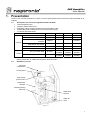
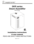
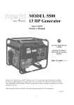
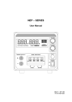
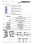
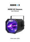
Humidifier overview
Electrical
compartment
Control panel
High voltage
quick connect
Evaporation
chamber
Internal plumbing
assembly
Water level
sensors
Water fill
valve
(Fig. 1)
2
SKR Humidifier
User Manual
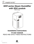
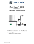
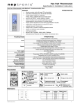
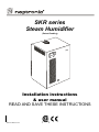
2. Definition
2.1.
Evaporation chamber
Assembly including the stainless steel cylinder and a cover equipped with an electric element.
High voltage
quick connect
Dimple for the alignment
of the cover
High temperature switch
quick connect
Cylinder
Steam outlet
Water coupling
(Fig. 2)
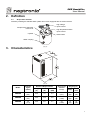
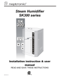
3. Characteristics
(Fig. 3)
Model
Capacity
kg/hr
(Lb/hr)
Electrical Requirements
Voltage
(V)
Current
(A)
Power
(KW)
Weight kg (lb)
Steam outlet
diameter
mm (in)
Empty
With
water
SKR3E
3.0
(6.6)
230
10
2.3
22
(7/8")
10
(22)
16
(35)
SKR4E
3.75
(8.2)
230
12.2
2.8
35
(1-3/8")
10
(22)
16
(35)
SKR5E
5.0
(11.0)
230
16.1
3.7
35
(1-3/8")
10
(22)
16
(35)
3
SKR Humidifier
User Manual
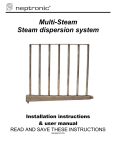
4. Mechanical installation
4.1.
General recommendations
4.2.
CAUTION: RISK OF ELECTRIC SHOCK. DISCONNECT THE HUMIDIFIER FROM THE ELECTRIC
SUPPLY BEFORE PROCEEDING TO THE MECHANICAL INSTALLATION.
IMPORTANT: Mechanical installation should conform to Local and National Codes.
Location: Plan a location which is easy to access in order to permit a proper inspection and servicing of
the humidifier.
Do not install humidifier where failure of the appliance could cause damage to the building structure or to
costly equipment.
This location should be well ventilated; the ambient temperature should not exceed 30°C (85°F).
The maximum distance between the humidifier and the steam dispersion tube in the ventilation duct
should not exceed 1.8m (6 feet) (maximum length of the steam hose).
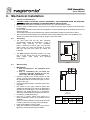
Positioning
The front panel and the left side (electrical
compartment) should be accessible in order to
permit easy servicing of the humidifier.
Leave a clearance of 0.91m (36”) from the front
panel, 0,30m (12”) from the left side, 6” (0.15m)
from the right side and 0.20m (8”) above the
humidifier.
The SKR humidifier should be mounted 1 to 1,2m
(39” to 47po) above floor for the installation of
water supply, drain piping and electrical
connections.
(Fig. 4)
4.3.
Wall mounting
IMPORTANT:
1. Risk of malfunction. The humidifier must
be level.
2. Risk of overheating. Do not block the
ventilation openings located on the top,
front, sides and rear of the cabinet.
Check the solidity of the chosen support or wall
(bricks, concrete, stud partition wall, etc) on which
the humidifier will be mounted (see page 3 for the
weight of the unit).
Use the keyholes located on the back panel of the
humidifier.
Drill holes for the upper anchors (holes with
eyelets) into the support or wall as per dimensions
specified in the table (fig.5). The hole dimensions
(diameter and depth) should be in accordance
with the recommendations of the chosen anchors.
If necessary, install bolt anchors.
Insert the 2 screws (holes with eyelet) of a
minimum diameter of 6mm (1/4”) (screws are not
supplied).
Leave a clearance between screw heads and wall
in order to permit the mounting of the humidifier.
Hang the humidifier on the 2 screws.
When the humidifier is positioned on the screws,
tighten the screws to secure the humidifier.
(Fig. 5)
Front view
Model
SKR
Dimensions mm (in)
A
B
C
51
78
37
(2”)
(3.06”)
(1.44”)
4
SKR Humidifier
User Manual
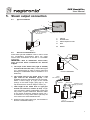
5. Steam output connection
5.1.
Typical installation
4
1
3
2
R: 12'’ (307mm)
minimum
1
Slope 15% minimum
1
2
3
4
Clamps
Flexible hose
Steam dispersion tube
Duct
R
Radius
(Fig. 6)
5.2.
General recommendations
Follow these general installation rules in order to avoid
any condensation accumulation which can cause
severe water accumulation in the duct or a humidifier
malfunction.
IMPORTANT: Risk of malfunction. Avoid kinks,
sags and areas where condensate can become
trapped.
a)
b)
c)
d)
The slope of the steam hose (rigid or flexible)
should not be less than 15% (7 horizontal lengths
for 1 vertical length) in order to ensure continuous
drainage of condensation back to humidifier or to a
steam trap.
The lowest point of any steam hose or rigid
pipe must be the humidifier (fig.7b). If the
humidifier cannot be the lowest point of the piping,
install a steam trap(s) (S Type) at the lowest
point(s) of the steam supply piping (fig.7c). This
trap should have a minimum height of 76mm (3”).
Total length of the steam hose or rigid pipe
should not exceed 1,8 meters (6 feet). Longer
runs will result in added condensation losses and
may result in system malfunction. Minimum radius
of any change of direction should be 307mm (12'').
A maximum of 2 long radius elbows (307mm) are
to be used on the steam distribution line.
Whenever using rigid copper pipe, use insulation to
diminish condensate build up.
Sag
Kinks
(Fig. 7a)
Incorrect installation
Slope
15% minimum
R: 12 '' (307mm)
minimum
Steam hose
Insulated copper
pipe (by others)
R>12''
(307mm)
(Fig. 7b)
3'' (76mm)
Steam trap S
(Fig. 7c)
Correct installations
5
SKR Humidifier
User Manual
5.3.
Recommendations for steam distribution piping
Steam dispersion
Steam outlet
tube
Model
Diameter
Length
Qty
mm (in)
mm (in)
1
22 (7/8")
229 (9")
SKR-3E
1
35 (1-3/8”)
356 (14")
SKR-4E / 5E
MAXIMUM allowable duct
static pressure at
dispersion tube location
Pa (in. water)
125 (0.5”)
125 (0.5”)
IMPORTANT: RISK OF MALFUNCTION. THE STATIC PRESSURE AT THE DISPERSION TUBE
LOCATION SHOULD NOT BE GREATER THAN 125 Pa (0.5”) DURING OPERATION. FAILURE TO
DO SO WILL VOID THE WARRANTY.
For a higher static pressure, use the Neptronic SKE commercial series humidifier.
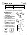
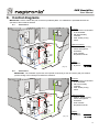
5.4.
Recommendations for the location of the steam dispersion tube
IMPORTANT: Risk of malfunction.
1. Do not split the steam output piping to
supply more than one duct.
2. Do not reduce the diameter of the steam
hose or piping. Hose and piping diameter
must be the same as the diameter of the
humidifier steam outlet.
Air flow
Min. 8”
(200mm)
Air flow
4”(100mm)
Provide a minimum of 460mm (18”) of straight
duct,
without
obstructions
or
elbows,
downstream of the dispersion tube.
Select an accessible location in the supply air
duct.
For the SKR3E, use a template and drill a 38mm
(1-1/2") hole in the supply air duct for the
installation of the of 22mm diameter dispersion
tube.
For the SKR4E & 5E, use a template and drill a
51mm (2") hole of in the supply air duct for the
installation of the of 35mm diameter dispersion
tube.
Secure the dispersion tube bracket to the duct
using sheet metal screws (not included).
In a vertical duct installation the holes of the
dispersion pipe should be aligned with the air
flow (see fig. 8d & 8e below).
3”(76mm)
(Fig. 8a)
Horizontal duct with
a minimum height of 8” (200mm)
Air flow
Air flow
H>=10”
(254mm)
1/3 H
(Fig. 8b)
Horizontal duct with
a minimum height of 10” (254mm)
L: M
(200 in 8'’
mm
)
Air flow
Down to up
L/2
Air flow
Air flow
(Fig. 8d)
Alignment of dispersion pipe
in a vertical duct
for the SKR3E
(Fig. 8e)
Alignment of dispersion pipe
in a vertical duct
for the SKR4E/5E
L/2
(Fig. 8c)
Mounting of the dispersion tube
in a vertical duct
6
SKR Humidifier
User Manual
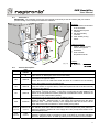
6. Plumbing connections
The SKR humidifier can operate with soft or hard water. Therefore, for normal operation, no pre-treatment of
water is necessary.
IMPORTANT: Plumbing installation should conform to Local and National Codes.
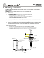
6.1.
Water supply
Water inlet specifications:
IMPORTANT: Risk of malfunction, do not use demineralized water.
Inlet water pressure: 1 to 4,8 bars (15 to 70 psig)
IMPORTANT: Risk of malfunction. Do not reduce water supply flow.
Maximum temperature: 30°C (85°F)
15mm (3/8'') standard copper supply water connection
To facilitate servicing, a shut off valve (not supplied) should be installed in the water supply line, close to
the humidifier.
It is recommended to install a standard strainer in the water supply line.
If required, an air chamber made of copper pipe (see fig. 9) will absorb hydraulic shock, avoiding water
hammer, when the fill valve closes. There are other standard types of air chambers commercially
available.
Please follow the steps below:
1.
Connect 15mm (1/2”) copper pipe to the 15mm (1/2”) braided hose (supplied).
2.
Hand tighten the swivel top 20mm (3/4”) fitting to the male threaded valve connection.
IMPORTANT: Risk of damage to the valve, do not use wrench to tighten swivel.
F ill va lve
(in th e h u m id ifie r)
Cap
(b y o th e rs )
H u m id ifie r b a s e
A ir c h a m b e r to
a vo id w a te r h a m m e r
(b y o th e rs )
M a le th re a d e d
v a lv e c o n n e ctio n
Approximatively 457 mm
S w ive l to p
W a te r s u p p ly
b ra id e d h o se
1 5 m m c o p p e r p ip e
(b y o th e rs)
¼ S h u t o ff va lve
(b y o th e rs )
(Fig. 9)
7
SKR Humidifier
User Manual
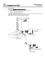
6.2.
Drain connections
IMPORTANT: No external drain traps are required.
Drain outlet specification:
Main drain 15mm (1/2”) standard copper (evaporation chamber).
Pan drain 15mm (1/2”) standard copper.
Water drain temperature: 60°C (140°F).
Two pipes minimum 25mm (1”) (by others) must be inserted over the humidifier outlet pipes
(fig.10). This will create a critical air gap at the drain connections.
NOTE: This air gap is critical for normal drain siphon operation.
SK
R
W a te r su p p ly
A ir c h a m b e r to a v o id
w a te r h a m m e r.
(b y o th e rs )
s e e s e ct 6 .1
P a n d ra in
M a in d ra in
(e va p o ra tio n ch a m b e r)
A ir g a p
M in im u m 2 5 m m p ip e
(b y o th e rs)
S h u t o ff v a lve
(b y o th e rs)
D ra in
N o d ra in tra p re q u ire d
(Fig. 10a)
Correct installation
M a in d ra in (e va p o ra tio n
c h a m b e r) m u s t b e s tra ig h t.
D o n o t in s ta ll e lb o w .
(Fig. 10b)
Incorrect installation
8
SKR Humidifier
User Manual
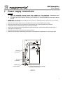
7. Power supply connections
CAUTION:
1. RISK OF ELECTRIC SHOCK, TURN OFF POWER AT THE EXTERNAL BREAKER/FUSED
DISCONNECT BEFORE PROCEEDING TO THE POWER SUPPLY CONNECTION.
2. To reduce the risk of electric shock, do not connect to a circuit operating at more than 150V to
ground.
IMPORTANT: The wiring to the humidifier should be done by a qualified electrician and conform to procedures,
regulations and local codes.
Ensure that the voltage required by the humidifier is the same as the available power supply.
Ensure that the size of the wire conductors is appropriate for the current required by the humidifier.
A dedicated external breaker/fused disconnect must be installed.
The ground conductor must be equipped with ring terminal and be connected the indicated location (fig.11).
Use coppers conductors only.
Ensure that each terminal connection is properly secured.
Install the supplied strain relief bushing at the bottom of the electrical compartment for of the supply cable.
Terminal
connection
Ground
connection
Opening for
control cables
Strain relief bushing for passage
of the electrical cable
(Fig. 11)
Left side view
9
SKR Humidifier
User Manual
8. Control diagrams
IMPORTANT: Use the cables with jack connectors provided by NEP. No substitution is permitted because the
operation of the unit will be affected.
8.1.
Control kit R
Controls:
PCB: Printed Circuit Board
in the humidifier.
HR: Wall humidity
controller.
APS: Airflow proving
switch.
Optional controls:
(Fig. 12)
*
APS/HL: Airflow proving
switch and high limit
humidistat.
*
OTW: Window
temperature sensor.
Cables:
Included:
By others:
8.2.
Control kit D
IMPORTANT : The ventilation system fan must operate continuously so the duct sensor (HD) can obtain a
precise reading of the humidity level inside the residence.
Controls:
PCB: Printed Circuit Board
in the humidifier.
HD: Duct humidity
controller.
APS: Airflow proving
switch.
Optional controls:
(Fig. 13)
*
APS/HL: Airflow proving
switch and high limit
humidistat.
*
OTW: Window
temperature sensor.
Cables:
Included:
By others:
10
SKR Humidifier
User Manual
8.3.
Control kit S
IMPORTANT : The ventilation system fan must operate continuously so the duct sensor (HD) can obtain a
precise reading of the humidity level inside the residence.
Controls:
PCB: Printed Circuit Board
in the humidifier.
SR: Remote set point
controller
HD: Wall humidity
controller.
APS: Airflow proving
switch.
Optional controls:
(Fig. 14)
*
APS/HL: Airflow proving
switch and high limit
humidistat.
*
OTW: Window
temperature sensor.
Cables:
Included:
By others:
8.4.
Controls description
Part
Control
Description
number
See section Printed Circuit Board in the humidifier. It incorporates all the control functions.
PCB
(See section 10–Description of the Control PC board)
10
Wall humidity controller with set point adjustment knob and an alarm indicator (red)
(see section 14-Types of alarm).
HR
HRR100
Locate this item on an inside wall which will serve as a reference for the humidity
level in the residence or the controlled space.
Remote set point controller with set point adjustment knob and an alarm indicator
(red) (see section 14-Types of alarm). This item requires the use of the duct humidity
SR
SRR100
controller (HD) HRD100.
Duct humidity controller with set point adjustment knob and an alarm indicator (red)
(see section 14-Types of alarm). If this item is used with the (SR) SSR100, the
switch on the (HD) HRD100 must be positioned at ROOM SET POINT, otherwise set
HD
HRD100
the switch to DUCT SET POINT (default).
Install this item in the return duct of the ventilation system.
Airflow proving switch with status indicator (green). The indicator is on when
airflow is detected. Install this item on the supply duct up-stream from the steam
APS
AFPS100
dispersion tube. Insert one extremity of the transparent tube into the duct and the
other end into the tube connection P1 of the airflow proving switch.
Airflow proving switch and a high limit humidistat with status indicator (green).
APS/HL
HRDFS100 The indicator is on when airflow is detected. This item replaces the (APS) AFPS100.
(Optional)
(Optional)
Install the (APS/HL) HRDFS100 in the supply duct 1.5m (5 feet) down-stream of the
steam dispersion tube.
Window temperature sensor. The OTW is used to prevent condensation on
OTW
OTW
windows. Install the OTW on the bottom corner of the glass on a window oriented to
(Optional)
(Optional)
the north. Requires 2 wires, 22 AWG (by others) for the connection to the humidifier.
IMPORTANT : Maximum length of each control cable is 30m (100 feet).
11
SKR Humidifier
User Manual
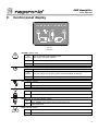
9.
Control panel display
(Fig. 15)
Front panel
"ALARM" Indicator (red)
O
flashing
O
O
One or more abnormal conditions exist.
(see section 16-Types of alarm)
Maintenance is required, the humidifier is OFF.
Normal operation.
''POWER'' Push button and Indicator (green)
O
The push button is in the ON position.
O
flashing
O
The push button is in the OFF position and the humidifier is powered.
Humidifier is not supplied with electric power.
"FILL" Indicator (yellow)
O Water supply valve is open.
O
Water supply valve is closed.
"STEAM" Indicator (green)
O
O
Humidifier is producing steam.
Humidifier is not producing steam.
''DRAIN'' Push button and Indicator (yellow)
Humidifier is in automatic or manual drain mode.
O
Press ‘’DRAIN’’ push button to stop an on-going drain cycle.
O
Drain mode is off.
''FAN'' Indicator (green)
O
O
The contact to activate the ventilation system fan is closed.
The contact to activate the ventilation system fan is open.
12
SKR Humidifier
User Manual
10. Description of the control PC Board
The Printed Circuit Board is equipped with an advanced microprocessor, which controls all humidifier
functions.
IMPORTANT: Risk of malfunction, use only jack connection control cables provided by NEP Ltd. Do not
substitute.
10.1.
P.C. Board
Safety HV cover
Phone jack connector (TJ2) to connect the airflow
proving switch (APS) or the integrated airflow proving
switch and the high limit humidity controller (APS/HL).
Phone jack connector (TJ1) to connect the wall
humidity controller (HR) or duct humidity controller
(HD).
Terminal (TB1) to connect the window temperature
sensor (OTW).
Dip switch (DS1) settings:
TB4
TB1
TB5
TJ1
Drain every 2 hours of
operation
JP3
TJ2
TJ1
ON
1
Drain every 6 hours of
operation
ON
1
2
DS1
ON
3
High limit humidistat is
not used
1 2 3
DS1
TB1
2
''Service required''
alarm appear after
750 hours of operation
Fuse
F3
TJ2
4
Dry contact (TB4) for remote alarm annunciation.
(1A, 24 Vac)
3
F2
TB4
2
Dry contact (TB5) to activate the ventilation system fan
on call for humidity. (3A, 24 Vac)
TB7
1
TB5
3
''Service required''
alarm appear after
1500 hours of
operation
(Fig. 16a)
P.C. Board top view
High limit humidistat
is used.
APS/HL (HRDFS100)
(Fig. 16b)
Dip switch setting
Note: Depending on the local water conditions, service of
the humidifier may be required prior to the ''service
required'' alarm setting (see section 14, Maintenance).
13
SKR Humidifier
User Manual
11. Start up procedure
Follow this start-up procedure to avoid improper system operation:
1. Ensure that steam distribution, electrical and plumbing connections have been done in accordance with the
instructions in this manual.
a) Remove the humidifier cover.
CAUTION: RISK OF ELECTRIC SHOCK, ENSURE THAT THE POWER IS TURNED OFF BEFORE
REMOVING THE COVER.
b) Ensure that the control wiring has been made in accordance with the instructions in this manual.
c) Ensure that dip switches (section 10, DS1) are correctly set.
d) Verify that the drain connections are connected to an open main drain of sufficient diameter.
e) Re-install the humidifier cover.
2. Open the water shut off valve (external to the humidifier).
3. Turn on the power to the humidifier at the breaker/fused disconnect. The ''POWER'' indicator, located on the
control panel, will flash.
4. Press the ''POWER" push button located on the control panel. The ''POWER" indicator will stay on
continuously.
5. Perform a manual cleaning cycle:
a) The fill cycle is activated automatically when the evaporation chamber does not contain water.
b) When the ''FILL'' indicator is off, press the “DRAIN” push button.
c) The ''DRAIN'' indicator will come on and the water will drain from the evaporation chamber.
d) The evaporation chamber will fill with water and drain again.
e) When the ''DRAIN'' indicator turns off, press on the ''POWER" push button.
f) Repeat steps ''b'' through ''e'' one more time to ensure proper cleaning of the evaporation chamber.
6. Your humidifier is now fully operational. No other action is necessary; your SKR humidifier will produce
steam upon demand from control(s).
12. Description of operation of the SKR
Press the ''POWER'' push button (if the indicator is flashing) to start the humidifier (''POWER'' indicator will
light continuously). If the evaporation chamber does not contain water, the fill cycle is activated
automatically (''FILL'' indicator is on).
If there is no demand from the humidity controller, the humidifier is in a standby mode (''STEAM'' indicator is
off).
On a demand of humidity, the contact to activate the ventilation system fan closes (''FAN'' indicator is on)
and the relays close to power the electric element in the evaporation chamber (''STEAM'' indicator is on).
The water in the evaporation chamber will start to boil and evaporate. The steam is released through the
opening in the cover of the evaporation chamber. The steam will travel in the flexible steam hose and
disperse inside the supply duct through the steam dispersion tube.
During the evaporation sequence, a certain amount of water is evaporated. The water supply valve will
open to replenish the water in the evaporation chamber.
Depending on the selected drain period (section 10, fig.16b, DS1-1), the water in the evaporation chamber
will be drained (''DRAIN'' indicator is on) to renew the water and to evacuate the minerals inside the
evaporation chamber.
The SKR operates at full capacity until the programmed humidity level set point is reached. When the set
point is reached, the humidifier will revert to standby mode. The contact to activate the ventilation system
fan (section 10, fig.16a, TB-5) will remain closed for a period of four minutes after steam production has
stopped.
When the humidity level is below the set point, the humidifier will produce steam again. If there is no
humidity demand for a period of more than 72 hours, the humidifier will drain the water from the evaporation
chambers automatically and go into standby mode
14
SKR Humidifier
User Manual
13. Shut-down procedure
During seasonal shut down, the humidifier should be placed out of service.
1. Press ''DRAIN" push button to empty the water from the evaporation chamber, the ''DRAIN'' indicator will be
on.
2. Once the cycle has ended, the ''DRAIN'' indicator will turn off. Close the shut off valve (external to the
humidifier) on the water supply line.
3. Open the main power breaker/fused disconnect switch to the humidifier.
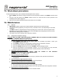
14. Maintenance
14.1.
General
IMPORTANT: Failure to perform the required periodic maintenance will void the warranty.
The required cleaning frequency can vary from every 2 months to once a year depending on local water
conditions.
The SKR humidifier is equipped with an internal operating hour counter and a ''service required'' alarm.
Depending on the local water conditions, service of the humidifier may be required prior to the ''service
required'' alarm setting (section 10, DS1-2).
The routine service is a cleaning of the evaporation chamber.
14.2.
Evaporation chamber cleaning
CAUTION: RISK OF BURN. THE EVAPORATION CHAMBER AND ITS CONTENTS CAN BE EXTREMELY
HOT, CHECK TEMPERATURE BEFORE HANDLING.
1. Cooling down and draining of the evaporation chamber.
a) Press ''DRAIN'' push button on the control panel. The humidifier will initiate a drain cycle.
The ''DRAIN'' indicator will turn on.
b) The ''DRAIN'' indicator is on and the water is drained from the evaporation chamber.
c) The evaporation chamber will refill with water and drain again.
d) When the ''DRAIN'' indicator turns off, the ''POWER'' indicator will begin to flash.
e) Check the temperature of the evaporation chamber. If it is cool enough go to step #2 below,
otherwise repeat draining of the evaporation chamber (step #1) until is cold enough.
2. Shut down of the electrical supply.
CAUTION: RISK OF ELECTRIC SHOCK, TURN OFF POWER AT THE EXTERNAL
BREAKER/FUSED DISCONNECT BEFORE SERVICING.
a)
Remove the cover of the SKR Humidifier.
3. Disconnecting the heating element.
a) Unscrew the high voltage quick connect (see fig.2), located on the right side of the electrical
compartment.
4. Disconnecting the high temperature switch.
a) Disconnect the high temperature switch quick connect (see fig.2).
5. Disconnecting the steam hose and the water pipe.
a) Loosen clamp on the steam hose connection.
b) Remove the steam hose from the top of the evaporation chamber.
c) Unscrew the water piping coupling located on the lower right hand side of the evaporation chamber.
6. Removing the evaporation chamber.
a) Remove the evaporation chamber from the humidifier cabinet.
15
SKR Humidifier
User Manual
7. Opening the evaporation chamber.
a) Unfasten the 3 latches located around the evaporation chamber.
Caution: Risk of injury, latches are tight. It is recommended to use pliers or a screwdriver to
unfasten the latches.
b) Remove the cover from the evaporation chamber.
c) Do not misplace the gasket located between the cover and the cylinder.
8. Cleaning the evaporation chamber.
a) Pour out any remaining water and scale from the bottom of the evaporation chamber
b) Clean out the remaining scale, use a non-metallic brush and water. Some vinegar or any weak acid
for cleaning stainless steel may be required.
IMPORTANT: The use of wire brush or any non-recommended acid will void the warranty.
c) If the amount of scale to be removed is significant, the service required alarm setting and/or the
drain rate (section 10, DS1) may be set too high for the local water conditions.
Too much scale may impair the normal operation of the humidifier or damage it. In this case,
increase the frequency of maintenance as necessary.
9. Cleaning the electric element and cover.
a) The cover of the evaporation chamber and element will, in general, not require cleaning.
However, if cleaning is required, proceed as per the cleaning of the evaporation chamber.
IMPORTANT: The use of wire brush or any non-recommended acid will void the warranty.
10. Checking the gasket
a) Check the gasket. The gasket should not be cracked.
The gasket must be replaced a minimum at every second maintenance of the evaporation chamber
or after one year of operation. Replace more frequently if required.
11. Reassembling the evaporation chamber.
a) Rinse out the cylinder and the cover with water.
b) Place the gasket inside the cover before installing the cover on the evaporation chamber.
c) Align the dimple on the cover with the latch located nearest to the water drain/fill coupling (fig.2).
d) Tighten the three latches around the cover.
e) Replace the evaporation chamber in the humidifier.
f) Tighten the water drain/fill coupling.
g) Replace the steam hose on the outlet of the evaporation chamber and secure steam hose with the
clamp.
h) Reconnect the high temperature switch connector and the high voltage connector of the heating
element.
CAUTION: RISK OF OVERHEAT AND FIRE, MAKE SURE THE HIGH VOLTAGE CONNECTOR
IS PROPERLY LOCKED.
i) Replace the cover on to the humidifier and lock it.
12. Start-up of the humidifier.
a) Close the main power breaker/fused disconnect switch to the humidifier.
Reset of the operating hours to zero: Press ''POWER'' push button to turn OFF the humidifier, if
necessary, then press and hold the ''POWER'' and ''DRAIN'' push buttons for ten seconds
(section 16-Types of alarm, Reset).
b) Press the “POWER” push button. The “POWER” indicator on the control panel will light.
c) The humidifier will go into a fill cycle; the ''FILL'' indicator will be on.
d) If there is a humidity demand, the humidifier will produce steam.
16
SKR Humidifier
User Manual
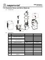
15. Exploded View and Bill of Material
15.1.
Exploded view
Option L
only
N
(Fig. 17)
15.2.
Bill of Material
Item
Description
Model
Part number
A
Evaporation chamber cylinder
SKR-3E / 4E / 5E
SW SKRCONT-ASSY
B
Evaporation chamber cover
C
SKR3E
SP 9011
SKR-4E / 5E
SP 9012-M
Evaporation chamber gasket
SKR-3E / 4E / 5E
SP 9030
D
Heating element
SKR3E
SKR4E
SKR5E
SE 5991
SE 5992
SE 5993
E
Heating element gasket
SKR-3E / 4E / 5E
SP 1005
F
High temperature switch
SKR-3E / 4E / 5E
SP 3035
G
Water level sensor assembly
SKR-3E / 4E / 5E
SW SKRLEV-ASSY
H
Water level sensor tube
SKR-3E / 4E / 5E
SP 1025
I
Water fill valve
SKR-3E / 4E / 5E
SP 6004
J
Drain pipe assembly
SKR-3E / 4E / 5E
SW SKRDRAIN-ASSY
K
Main plumbing assembly
SKR-3E / 4E / 5E
SW SKRPIPE-ASSY
L
Terminal block
SKR-3E / 4E / 5E
SP 9046
M
Main PC board
SKR-3E / 4E / 5E
NW SKREMAINSS
N
SKR-TRIAC PC Board
(Option L)
SKR-3E / 4E
SKR5E
NW SKRL-2SS
NW SKRL-3SS
17
SKR Humidifier
User Manual
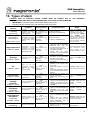
16. Types of alarm
CAUTION: RISK OF ELECTRIC SHOCK, POWER MUST BE TURNED OFF AT THE EXTERNAL
BREAKER/FUSED DISCONNECT BEFORE REMOVING THE COVER OF THE HUMIDIFIER.
IMPORTANT: A corrective action must be taken before doing a reset.
The alarm contact (normally open) will close when there is an alarm.
ALARM
Condition
Consequences
Corrective actions
Indicator
Service required
1. Flashing
continuously
Service required
2. Indicator is
continuously on
(SKR Humidifier shut off)
High temperature
2 flashes + pause
Drainage
3 flashes + pause
Fill
4 flashes + pause
Level sensors
5 flashes + pause
Wall or duct
humidity
controller
Operating
hours
exceeded the service
required alarm hour
setting (DS1-2)
Alarm.
No interruption of
the operation of the
humidifier
Proceed to a service
(See section 14-Maintenance)
Operating
hours
exceeded by more than
50 hours the service
required alarm setting
(DS1-2)
Alarm.
The operation of the
humidifier
is
interrupted
Proceed to a service
See section 14-Maintenance)
Temperature in the
evaporation
chamber
exceeded the preset
temperature of the high
temperature switch
Alarm.
The operation of the
humidifier
is
interrupted
Drainage sequence is
not correct
Alarm.
The operation of the
humidifier
is
interrupted
Time
to
fill
the
evaporation
chamber
exceeded the preset
time
in
the
microprocessor
Alarm.
The power to the
heating element is
interrupted
The level sensors do
not detect the water
level correctly
Alarm.
The operation of the
humidifier
is
interrupted
Sensor not detected or
not operational
Alarm.
The power to the
heating element is
interrupted
Sensor not detected or
not operational
Alarm.
The power to the
heating element is
interrupted
Humidity level in the
duct exceeded the high
limit set point
Alarm.
The power to the
heating element is
interrupted
The unit is not powered
_
6 flashes + pause
High limit duct
humidistat
(if available)
7 flashes + pause
High limit duct
humidistat
(if available)
8 flashes + pause
Power
Not flashing
Check that the static pressure
inside the duct at the steam
dispersion tube does not
exceed 125Pa (0.5” W.G.).
Check that the steam hose is
not blocked or kinked.
Check
that
the
water
connection on the evaporation
chamber is not blocked.
Check
that
the
water
connection to the evaporation
chamber is not blocked.
Check that the drain piping is
not blocked.
Check that the shut off valve
installed on the supply water
line is open.
Verify the operation of the fill
valve.
Check that the fill valve strainer
and the external strainer are not
blocked.
Check that the sensors are
properly connected.
Check that the sensors are
clean.
Check that the NEP supplied
cable is connected between the
HRR100 or HRD100 and the
TJ1 terminal on the PC board of
the SKR.
Check that the NEP supplied
cable is connected between the
HRDFS100 and the TJ2
terminal on the PC board of the
SKR.
Check that the high limit set
point is sufficiently high (85%
R.H.).
Check
that
the
distance
between the sensor and the
steam distribution tube is
sufficient (5 feet/1.5m).
Check that the main power
breaker or fused disconnect
switch is closed
Reset
Press the ''POWER'' push
button to turn OFF the
humidifier (if necessary).
Press and hold ''DRAIN''
and
''POWER''
push
buttons simultaneously for
ten seconds. These two
indicators will turn on after
the ten seconds. Release
the push buttons.
Press the reset button on the
high temperature switch
device located on the
evaporation chamber cover.
Press on the DRAIN push
button
Automatic reset when the
proper water level is reached
Press on the POWER push
button
Automatic reset when the
humidity
controller
is
detected
Automatic reset when the
humidity
controller
is
detected
Automatic reset when the
humidity level inside the duct
is below the set point
Automatic reset when the
unit is powered
18
SKR Humidifier
User Manual
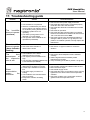
17. Troubleshooting guide
Problem
The humidifier
does not operate
(no alarm)
Causes
Corrective actions
The humidifier is not powered.
Airflow is not detected by the airflow
proving switch. The indicator (green)
on the airflow proving switch is not on.
Ventilation system fan is not
operating.
The airflow proving switch is not
detected or not operational.
The high limit duct humidistat is not
operational (if available).
Check for the main power supply and fuses.
Check that the sensor tube is connected properly
inside the duct and to the AFPS100.
Check that the AFPS100 or HRDFS100 is located
properly.
Check the fan operation.
Check that the NEP supplied cable is connected
between the AFPS100 or HRDFS100 and terminal
TJ2 on the PC board of the SKR.
Check the high limit duct humidistat operation by
setting the DS1-3 (section 10, fig.16b) to the off
position. If humidifier operates normally replace the
HRDFS100.
The humidifier
does not operate Check the alarm indicator to
determine the cause
(alarm indicator
flashing)
The installation of the steam
The
duct
dispersion tube is incorrect.
downstream of The capacity of the humidifier is too
high.
the
dispersion
The high limit humidistat (HRDFS100)
tube is wet
is not activated (if available).
Water
accumulation
under
the
humidifier
The drain pipes are leaking, are
obstructed or the slope is incorrect.
A drain trap is installed on the drain
line.
The water supply connection is
leaking.
The installation of the flexible steam
hose is incorrect.
Evaporation chamber is leaking
steam.
See section 16-Types of alarm to correct the
situation
Check if the steam dispersion tube is installed
correctly.
Install a high limit duct humidistat (model
HRDFS100) if required.
Verify the setting of the DS1-3 (section 10, fig.16b).
Check all the couplings and drains under the unit.
Remove all drain traps.
Check water supply circuit.
Check that the clamp on the steam hose is properly
tightened on the steam outlet of the evaporation
chamber.
Check the condition of the evaporation chamber
gasket inside the evaporation cover.
19
SKR Humidifier
User Manual
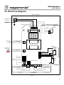
18. Electrical diagram
SKR humidifier
Power supply
terminals
Live
Return
Printed circuit board
Mechanical compartment
1
2
3
4
TB7
Heating
element
Quick
Connect
F2
F3
Fuse
Pilot - Dry contact
3A/24Vac
TB5
To fan
relay
Powered
230 Vac
Fill Valve
Powered 30mA/24Vac
High
temp.
switch
HI probe
Low probe
Common
TJ2
APS
APS/HL
JP3
!
Pilot - Dry contact
1A/24Vac
TB4
To external
alarm relay
TJ1
HR/HD
ON
DS1
OTW
1 2 3
TB1
See details
Section 8.
Dip switches
Alarm LED (Red)
Power LED (Green)
On/Off Push button
Fill LED (Yellow)
Quick
Connect
W ater
level
sensor
Fan LED (Green)
Drain LED (Yellow)
Drain Push button
Steam LED (Green)
Access panel
(Fig. 18)
20
SKR Humidifier
User Manual
19. Personal notes
21
SKR Humidifier
General conditions of sale & warranty
1. General
Unless otherwise arranged, in writing, the acceptance of the
Order Confirmation by the purchaser includes acceptance of
the "General Conditions of Sale and Warranty" of National
Environmental Products, Ltd hereafter referred to as NEP.
2. Incoterms
The international rules for interpretation of trade terms
"Incoterms" as defined by the ICC Incoterms publication no. 460
from 1990, shall apply to the commercial terms used herein.
3. Confirmation of Order
NEP shall not be deemed to have accepted an order until
written "Order Confirmation" from NEP is issued to the
purchaser.
It is the responsibility of the purchaser to verify that all
information concerning his/her order is correct and to notify NEP
In writing, of any discrepancy prior to the order being shipped. In
the event of a change or correction to an existing order, a second
"Order Confirmation" will be issued by NEP.
4. Price
Our prices are net, Ex-works Montreal in U.S. Currency,
unless stated otherwise.
Minimum orders shall be $50.00 minimum.
Shipping and Handling charges are $5.00 minimum per
order unless the shipment is billed to the purchaser's account or
shipped freight collect.
NEP reserves the right to adjust accepted prices in the
event of alterations in rates of exchange, variations in costs of
materials, changes in wages, interference on the part of the
Government or similar conditions over which NEP has no control.
5. Payments terms
Major credit cards, C.O.D., Prepayment.
For open account, invoices are payable within 30 days from
the date of invoice without no deduction, unless specify
otherwise.
An interest charge of 2% per month will be included on all
overdue payments.
No new order will be process if invoices are not paid within
45 days.
6. Transfer of ownership
The goods shall remain the property of NEP until the full
payment for the goods has been received by NEP.
7. Delivery terms
Shipments are Ex-works 400 Lebeau, St Laurent, Quebec,
H4N 1R6, CANADA unless notified otherwise.
Unless special instructions, the order will be delivery in the
way which NEP deems best without guaranteeing this to be the
cheapest way of transport.
For International Order, a written designation naming the
freight forwarding agent is required and will remain in effect until
notified otherwise.
Any discrepancy, damage or breakage should be reported
in writing both to NEP and to the Carrier within 5 working days
from the receipt date.
8. Risk
From the moment of delivery, the purchaser shall bear all risks
for the goods and NEP shall not be responsible for loss and
damage incurred during transportation.
9. Delivery time
Delivery time is stated approximately and depends on the
product ordered, please allow a minimum of:
a) 2 weeks for processing North American order.
b) 6 weeks for processing International order.
We will make every effort to adhere to our delivery
promises, but will not accept order or contract cancellation or any
liability for any direct or indirect losses that may arise for any
reason whatsoever as a result of our failure to adhere to such
promises.
10. Return of good
Goods received by the purchaser cannot be returned unless
a completed "R.M.A. Form" (Return Material Authorization Form)
has been issued by NEP's Customer Service.
Any returned goods must be sent to NEP 400 Lebeau, St
Laurent, Quebec, H4N 1R6, CANADA, unless stated otherwise
by the R.M.A. Form, accompanied with the completed "R.M.A.
Form", the R.M.A. number shall be prominently displayed on the
shipping box. Unauthorized returns will be refused.
Any returned goods must be sent freight prepaid. Any
goods that come to us freight collect will be refused and returned
to sender unless previously agreed to by us in writing on the
"R.M.A. Form".
Goods returned for credit shall be in condition for resale in
the original box and properly packaged. Units, accessories or
components that have been installed are not returnable and not
refundable. Credit is subject to an overhead charge of 30% of the
invoice plus shipping & handling if returned within 30 days of the
invoice date and 50% from 30 to 60 days.
Non standard product (SK units with special feature),
Multisteam manifolds and any DI unit are not returnable and not
refundable.
11. Warranty
Provided that the terms of payment are observed, the
purchaser is offered a warranty of 24 months from the original
purchase date of delivery for any NEP's standard product,
provided the equipment has been properly installed and operated
in accordance with NEP instructions.
The warranty covers faulty manufacture, design and/or
defective materials and is limited to the equipment and
components. The warranty shall cease to be valid in the event of
misapplication, incorrect installation, improper maintenance or
any other incorrect uses or misuse of the product.
For the SK series, the warranty furthermore ceases to be
valid if the user disconnects or removes any electronic or
mechanical components prior disconnecting the input power.
NEP assumes no responsibility for repairs made on equipment,
unless performed by NEP's authorized personnel.
The defective product or component shall be returned in
accordance with the paragraph 10 (Returns of goods) as
described in this document.
NEP agrees under the warranty to repair or replace (at the
discretion of NEP) such standard product or component, which
upon examination by NEP are found to be defective.
Product or component replaced or repaired under warranty
will be sent back to the purchaser, standard freight paid by NEP
Expenses in connection with traveling time, dismantling and
mounting shall not be paid by NEP
Guarantee for products or components sold but not
manufactured by NEP, is only given to the same extent as given
to NEP, however, not exceeding the normal NEP warranty.
Parts used for repairs are warranted for the balance of the
term of the warranty on the original humidifier or 90 days,
whichever is longer.
Any repair made, after the original warranty period, at the
NEP facilities are warranted for 1 month from the date of repair.
12. Proper law and jurisdiction
This contract is and shall be deemed to have been made in the
province of Quebec, CANADA, and shall in all respects, be
governed by the province of Quebec laws.
22