1
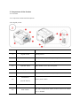
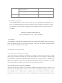
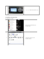
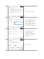
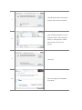
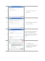
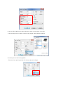
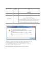
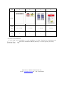
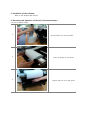
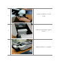
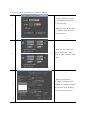
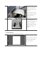
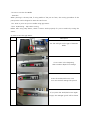
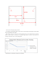
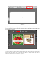
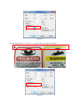
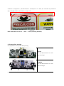
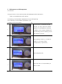
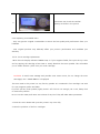
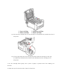
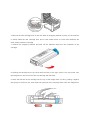
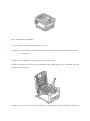
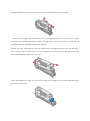
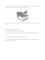
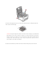
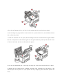
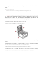
Bitek Technology, Inc. Any-002 User Manual Anytron. Digital Color Label Press Ver 1.0.0 (25-JULY-2014) Table of Contents 1. CERTIFICATION AND SAFETY ···················································································· 5 1.1. Status of certification························································································································· 5 1.2. Safety instructions ······························································································································ 5 1.2.1. Installation ····································································································································································· 5 1.2.2. In use················································································································································································ 5 1.3. Legal validity of this document ······································································································· 6 2. COMPONENTS OF THE PRODUCT ··········································································· 7 2.1. Overview ··············································································································································· 7 2.2. Component names and descriptions ······························································································ 7 2.2.1. Digital printer ······························································································································································· 7 3. INSTALLATION OF THE PRODUCT ··········································································· 8 3.1. Requirements for installation ··········································································································· 8 3.1.1. Overview ········································································································································································· 8 3.1.2. Place and environment ············································································································································ 8 3.1.3. Installation personnel ··············································································································································· 9 3.1.4. Delivery ··········································································································································································· 9 3.2. Installation of the press station ······································································································· 9 3.2.1. Checking of press station components ··········································································································· 9 3.2.2. Checking of place, carrying and installation ································································································· 9 3.2.3. Checking of a Various plug-in and operations ························································································· 10 3.3. Installation of the printer (digital press) ······················································································ 10 4. INSTALLATION OF PRINTER DRIVER ·····································································11 4.1. Installation of driver ························································································································· 11 4.2. Configuration of the Roll (Continuous Paper) Driver ································································ 15 4.3. Description of the Printing Mode ································································································· 17 4.4. Multiple of printing according to Image Length ······································································· 18 4.5. Inquiry and Download ····················································································································· 19 5. INSTALLATION OF THE SOFTWARE ·······································································20 6. MOUNTING AND OPERATION OF THE ROLL (CONTINUOUS PAPER) ···········20 6.1. How to Mount Paper ······················································································································· 20 6.2. How to Check the Alignment of Mounted Media ····································································· 22 7. PRINTING OPERATION ····························································································· 23 7.1. How to Use the Basics of Illustrator for Any-002 ······································································ 23 7.2. How to use Pre-Cut Media ············································································································· 25 7.2.1. How to print out pre-cut media using gap sensor ················································································· 25 7.2.1.1. H/W setting - Gap sensor tuning············································································································ 25 7.2.1.2. Editing S/W ························································································································································ 26 7.2.1.3 How to find right printing location ········································································································· 27 7.2.1.4. Location discrepancy between up and down side ·········································································· 33 8. PROCESS AFTER PRINTING ····················································································· 35 8.1. Digitalization of process after printing ························································································ 35 9. MAINTENANCE AND MANAGEMENT·································································36 9.1 Overview ·············································································································································· 36 9.2 Types of Errors on the Printer (Press) LCD Messages and Its Description ···························· 36 9.3 Checking of Consumables’ Replacement Cycle and Replacing ················································· 36 9.3.1 Checking of consumable’s replacement cycle ···························································································· 36 9.3.2. Replacing consumable items ····························································································································· 37 9.3.2.1. Toner cartridge replacement ······················································································································ 37 9.3.2.2. Image Drum replacement ··························································································································· 41 9.3.2.3. Replacing the Transfer Belt Unit··············································································································· 44 9.3.2.4. Fuser replacement ·········································································································································· 47 9.3.2.5. Clean the LED HEAD ······································································································································ 48 9.4. Purchasing of Consumables ··········································································································· 49 9.5. Inquiry and Download ····················································································································· 49 10. PRODUCT SPECIFICATIONS ··················································································· 49 11. SERVICE GUIDE AND PRODUCT WARRANTY ···················································· 51 11.1 Warranty ············································································································································ 51 11.2. A/S and inquiry ······························································································································· 51 1. Certification and Safety 1.1. Status of certification Registration Number : KCC-REM-BTI-ANY-002 1.2. Safety instructions - Because safety instructions are necessary to prevent accidents or dangers, please make sure to follow them to ensure that you use this product safely. 1.2.1. Installation - Install the product in a stable place without danger of falling. - Do not install the product in a place with high temperature or moisture. The product may not operate properly under these conditions and there might be a danger of electric shocks. - Do not use loose sockets or defective power cords, as there will be a danger of electric shocks and fire. - Plug the power cord into a socket and a multi-consent with an earth terminal. 1.2.2. In use - Do not carry out inspections or repairs except if you are a qualified persons. - Do not disassemble arbitrarily or subject the machine to impact or dropping. - Do not use around magnetic materials or store near them. - Use the product in a place without electromagnetic interferences. - Do not put things, which are heavy or have a risk of spillover, on the product. - Do not use chemicals or detergents etc. for cleaning the product. - Use only programs provided by or approved by Bitek. 1.3. Legal validity of this document - We inform you that this manual does not carry legal binding force, and we reserve the right to change this manual at will without giving a separate notice. 2. Components of the Product 2.1. Overview 2.2. Component names and descriptions 2.2.1. Digital printer No Name 2 Digital Printer 2-1 Top Cover Release Button 2-2 Top Cover 2-3 Operator Panel 2-4 Multi-purpose Tray 2-5 Front Cover Release Lever Description Printing device The top cover is opened by pressing the button. The cover is opened by pressing the button 1. Menu-based control and LCD panel Tray for using continuous media The front cover is opened by pulling the lever. PowerSwitch 2-6 Printer power switch (On/Off Switch) 2-7 AC Power Socket 2-8 Rear stacker Connection for printer power cable. Tray that accepts and stacks printed continuous media as it is released. 2-9 USB interface 2-10 Network Interface 2-11 ACC interface 2-12 Parallel interface Interface that directly connects a PC with the printer Interface to use the printer via a network 3. Installation of the Product 3.1. Requirements for installation 3.1.1. Overview -This product is a printing device and digital electronic communication equipment. Accordingly, this product can implement optimum printing quality only if it is installed in a place meeting environmental requirements for digital equipment as well as the conditions required for a label printer. For this reason, our company makes it a rule to professionally install our products by our staff or our designated agency’s personnel and we request that customers follow our personnel’s suggestion for the locations of the equipment along with the environmental requisites for optimal operation. 3.1.2. Place and environment -The operating environment of this product is as follows, and it should be installed in a place satisfying the specified conditions for temperature/humidity. In addition, considering the gross weight of this product, it should be installed on a level rack that can withstand a weight more than 3 times that of the equipment, at least. Additionally, cleanliness of the working area and minimization of dust is essential for high-quality printing in particular. Item Condition Value Temperature 17 - 27˚C Humidity 40 – 60% RH Environment Horizontal orientation Loading rack Minimum size Minimum supporting weight 250 Kg Antistatic ground Others 3.1.3. Installation personnel - Our company makes it a rule to visit in person to ensure a professional installation by our staff or our designated agency’s personnel. Please contact by [phone] or [email] if you have any questions about the product installation service performed by our personnel or any of our agents. Manufacturer: BITEK TECHNOLOGY INC, E-mail: [email protected], Tel : +82-32-834-4860 3.1.4. Delivery -The installation personnel will completely install this product and software (such as the printer driver) and also a test print a roll of continuous paper. At this time, the delivery will be completed by the customer’s signature on the receipt. 3.2. Installation of the press station 3.2.1. Checking of press station components - The press station is mounted or projected by a unwinder, sensor and cutter and is a smart station that is intricately connected with various semiconductor circuits and wires to electronically control these all components, rather than being a simple rack to put a printer on. Therefore, the same care is required as with the printer (digital press) when moving or installing it, so please follow understand the installation personnel’s instructions and this manual. 3.2.2. Checking of place, carrying and installation -carefully carry the press station to the place of installation selected previously in section 3.1.2 before the printer (digital press). This press station has a gross weight of 150Kg, with an overall size of (length) 71cm × (width) 193cm × (height) 70cm, which should be carried by at least 4 people. And in front side of the station, there is a PCB board. So you need to pay attention when you carry and install the station. 3.2.3. Checking of a Various plug-in and operations 3.3. Installation of the printer (digital press) Carrying, installation and securing of the printer: After unpacking the printer box, place the printer on the press station, and then secure the printer and the mechanics together tightly with bolts in the box (refer to the figure). Checking Existence of Various Consumables (Toner, Cartridge, Transfer Belt, Fuser) and Mounting: Various plug-in Checking of operation If you turn on the power of printer and the 1 message 'Ready to print' appears on LCD, it will be normally operated. ① ② ③ ④ 2 ① ~⑤: Check the IP. (refer to 4-1) ⑤ 4. Installation of printer Driver 4.1. Installation of driver 1. Execute [Device and Printer] on the start menu. 2. Click [Add a Printer] on the activated window. 3. Click [Add a Local Printer].. Click next as default value of [Use an existing port] when 4. connecting through a USB. Select [Standard TCP/IP Port] of [Make a New Port], and then click [Next] when using LAN. After entering a printer’s IP address, click [Next]. (Refer to the 3.3 Installation of the printer for checking the printer’s IP.) 6. Click [Have Disk]. 7. Click [Browse] after inserting the Anytron CD into the computer. After clicking [Computer] on the 8. finding location, select [Anytron Driver] in the [Anytron] media device, and then click the [Open]. 9. 10. Click [OK]. After checking the OKI WEB61, click [Next]. 11. After entering a printer name, click [Next]. 12. After selecting [Do not share this printer], click [Next]. After selecting [Set as the Default Printer], click [Checking a Test 13. Page] for checking the connection. (There should be A4 papers in the tray 1.) The installation will be 14. completed when pressing [Close] and [End] after identifying the printed test page. 4.2. Configuration of the Roll (Continuous Paper) Driver 1. After right clicking the Anytron driver in the [Devices and Printers], click the Default Print Setup. 2. Set the Size as the Super Long Paper in the Default Print Setup. 3. In the message box opened at this time, click the OK to change the paper source. 4. Enter a desired printing edit size into the Width, Length. (Ex- A4 size print: 210x297) 5. Footer margin the space between printed units, Start is the beginning point of the images, and cut is the cutting point after finishing all work. 6. Set the Adjust Mode as the No Adjustment when using regular roll media. 7. Set the Weight as the Labels 2 when using regular matt papers(art papers). 4.3. Description of the Printing Mode - There are three printing modes for the Any-002 as the figure.. Adjust Mode 센싱유무 설명 Normal O Print continuously after sensing the black mark once at the beginning No Adjustment X Print continuously without using the sensor (Default) Print consecutively by sensing every image unit’s black mark continuously Adjustable Mode to support pre-cut papers O (The value that determines the number of intervals in which for ‘in how many intervals of black marks the location should be adjusted’varies according to the label size.) 4.4. Multiple of printing according to Image Length - Multiples of images to be printed in Any-002 vary according to label size. For example, Length 100mm image is printed as multiples of five. Thus, 10(5*2) images are printed if you enter the number of output as ‘9’. This is equally applied in Adjustable mode. When printing 100mm image, adjust location at every 5 sensing. Case 1 2 3 4 0.5 ~ 2 inch 2 ~ 5 inch 5 ~ 10 inch 10 inch 20 5 2 1 Example The length of the data Quantity of data per page 4.5. Inquiry and Download - If you need more information on the installation of driver, download at www.anytron.net -002 Driver Installation Manual (PDF file), or contact [phone] or [email]. Manufacturer: BITEK TECHNOLOGY INC, E-mail : [email protected] Tel : +82-32-834-4860 5. Installation of the Software - Refer to the separate RIP manual. 6. Mounting and Operation of the Roll (Continuous Paper) 6.1. How to Mount Paper 1. 2. 3. Set the media into the unwinder. Press the guide to the center. Tighten the bolt to fix the guide. 4. 5. 6. Tighten the bobbin to fix the media. Install the media like this path of picture. Media installation is completed. 6.2. How to Check the Alignment of Mounted Media - Create a working window of a 215x200mm document on the illustrator. 1 - Make two vertical lines (90 ˚) of 200mm with two lines of the tool box. - Align the two lines as the 2 figure, respectively. (Align them at 5mm inside the base sheet.) - While printing about 2~3m(10~15 sheets),check 3 whether the image is printed at the center, and whether it is not inclined as printing. - Check the operating line whether the printed media has an equal margin at the both side. 4 - If the margins are not the same, adjust the unwinder’s guide to print them identically. If the operating line is printed at the center, put the 5 media on the rewinder to adjust the guide, and check whether the media is not inclined. 7. Printing Operation 7.1. How to Use the Basics of Illustrator for Any-002 Create a new file with a width of 1. 215mm and a desired height. ( Ex – 215 x 250 mm ) Make a black mark of 3 x 3mm on the top left of the base sheet. (EX *For AnyCut : make 2 black marks to the right and left side. 2. Right side is for blackmark sensor and left side is for vision camera. -Right side black mark size : 3x3mm -Left side black mark size: 10x5mm *For AnyBlade : refer to AnyBlade Manual. 3. Fetch an image to place as the desired form. The RIP converts it into a 4. printable file. (Save the file as a PDF format.) 7.2. How to use Pre-Cut Media - Overview When printing in the Any-002, if using media of the pre-cut form, the cutting procedure of the post-process can be skipped to save time and costs. 7.2.1. How to print out pre-cut media using gap sensor 7.2.1.1. H/W setting - Gap sensor tuning Before start using Gap Sensor, check if sensor works properly for pre-cut media by tuning the sensor. (1) how to tune the gap sensor picture Description 1. Put the red light on the gap of between labels. 2. It’s a screen in the beginning. *that numbers depend on settings. 3. Press the AUTO/OK button once. You can see that messge like picture. 4. If you press the AUTO/OK button again longer, the messgae ‘good’ will be shown. 5. If you press the AUTO/OK button again longer, the error message is shown like this picture, you have to tune again by repeating this course. 6. If you success the senssor tunning, When the sensor light on the gap between label, that light will be turned on and when the light of sessor is on the label, the light will be turned off. 7. If you success the sensing on the gap, Repeat this course on the Label. the sensing is completed. 7.2.1.2. Editing S/W (1) Giving exmaple, the following shows how to print out pre-cut label with given size in a picture below. . ※ The any-002 printer has 4mm of margin on right and left side. Therefore, it is not possible to make it fully printed on paper. 7.2.1.3 How to find right printing location - It is possible to place label image in same location using average value (Length) of sensing data which is generated by each page. - More sensing values you have more accurate average value you can calculate and you can place labels in same location for printing out. In general, length which is criterion to set location for printing is 3 M which is 10 or more sensing data. * Specifications for discrepancy range are as followings: Discrepancy range Cut sheet ± 0.4 mm Continuous paper First 3M ± 0.8 mm –No adjustment After 3M Continuous paper First 3M ± 0.7 mm - Adjustable After 3M ± 0.2 mm ± 0.4 mm * How to make paper in Illustrator a. As shown in <Figure 1>, run Illustrator and click, [File] -> [Create New]. <Figure1> b. Clicking [Create New] will bring up the window as shown in <Figure 2>. Enter width and height and click [OK]. <Figure2> * How to change image size in Illustrator When selecting an image, it shows W and H value as like <Figure 3>. W refers to Width and, H refers to Height. Change W and H value to modify image size. <Figure3> ④ As shown in <Figure 4>, paper with width of 215mm and height of 100mm. W: 215mm, H:100mm <Figure 4> ⑤ After creating paper, locate images to print out and make it fit to pre-cut media label size. ⑥ As Pre-cut label has 5mm of left margin, place an image for left label with 5mm margin from axis as shown in <Figure 5>. <Figure5> ⑦ Since left margin is 5mm and margin between label is 5mm, place an image for right label with 110mm margin (Left margin 5mm + Left label image 100mm + margin between right and left label 5mm=110mm) from axis as shown in <Figure 6>. <Figure6> ⑧ Set Y-axis to 0 to make the image fully fill up the paper in size of 100mm. ⑨ It is all done in Illustrator. Now it needs to set driver for printing out. ⑩ In Illustrator, click broght up. Click [File] -> [Print] at top left side, then window shown in <Figure 7> will be [Settings]. <Figure7> ⑪ Select any-002 and click [Set Printer]. <Figure8> ⑫ As shown in<Figure 9>, [Printer Settings] will open. On [Size] tab, select [Super Long Paper]. <Figure9> ⑬ When selecting Super Long Paper, window shown in <Figure 10>will appear. Enter width and height. Width of media to print out Length of pre-cut label Height margin between labels Location to start printing Mode for sensing * Refer to section 7.2.4 for further information on Adjust mode. <Figure10> - Width : Width of media(Roll). Note that this is not the size of image. - Length : Length of a pre-cut label. Image will be printed out according to the value.. - Footer Margin : Margin (Height) between labels. - Start : Start point of print. For example, Start point for <Figure 1> label should be 3. This is because the margin between labels is 3mm, after sensing, label is placed 3mm below. -Adjustable : When using Pre-cut label, make sure that Adjust Mode is set to Adjustable. ⑭ Click [OK], set The number of print and click [Print]. 7.2.1.4. Location discrepancy between up and down side If there is location discrepancy between up and down side, measure printed image size and adjust start value marked in red as shown in <Figure 11> to change location. It is recommended to enter decimals using accurate steel ruler.. Use (-) value when moved upper side than label size and (+) value for lower side <Figure11> Printed image shown in <Figure 12> is printed 1mm lower than actual label. <Figure12> <Figure13> As shown in <Figure 13>, set Start value to -1 and print it out. Then you can find it is printed out with changed location as shown in <Figure 14>. <Figure14> Note: Valid value for Start is -1336 ~ +1437 (including decimals) 8. Process after printing 8.1. Digitalization of process after printing Anycut you can laminate and cut with laser at one go. AnyBlade you can laminate and cut with knife at one go. ※ you can check relevant facts in www.anytron.net 9. Maintenance and Management 9.1 Overview 9.2 Types of Errors on the Printer (Press) LCD Messages and Its Description -Refer to the additional printer manual. 9.3 Checking of Consumables’ Replacement Cycle and Replacing 9.3.1 Checking of consumable’s replacement cycle -Installation Personnel (Name: Tel: ) If the printer is connected through Ethernet, you may check the residual 1 quantity of consumables by entering IP address on the internet address bar. The following is about checking on the LCD window of printer. After pressing a menu (∧) of panel in 2 [Ready To Print] state, select [Configuration] in [Functions]. 3 4 Select [Supplies Life]. Select the menu of consumables you want to check. 5 Cyan Drum may check the residual quantity as shown in the picture. 9.3.2. Replacing consumable items - Only use genuine original consumables to ensure the best quality and performance from your hardware. - Non original products may adversely affect your printer’s performance and invalidate your warranty. 9.3.2.1. Toner cartridge replacement -When the LCD display indicates TONER LOW, or if print appears faded, first open the top cover and try tapping the cartridge a few times to evenly distribute the toner powder. This will enable you to obtain the best “yield” from your toner cartridge. CAUTION: To avoid toner wastage and possible toner sensor errors, do not change the toner cartridge(s) until “TONER EMPTY” is displayed. The toner used in this printer is a very fine dry powder. It is contained in four cartridge: one each for cyan, magenta, yellow and black. If you do spill any toner powder, lightly brush it off. If this is not enough, use a cool, damp cloth to remove any residue. Do not use hot water, and never use solvents of any kind. They will make stains permanent. 1. Press the cover release and open the printer’s top cover fully. 2. Note the positions of the four cartridges. (a) Pull the toners release lever on the cartridge to be replaced fully towards the front of the printer. (b) Lift the right-hand end of the cartridge and then draw the cartridge to the right To release the left-hand end as shown, and withdraw the toner cartridge out of the printer. 3. Put the cartridge down gently onto a piece of paper to prevent toner from making your furniture. 4. Clean the top of the ID unit with a clean, lint free cloth. 5. Remove the new cartridge from its box but leave its wrapping material in place for the moment. 6. Gently shake the new cartridge from end to end several times to loosen and distribute the toner evenly inside the cartridge. 7. Remove the wrapping material and peel off the adhesive tape from the underside of the cartridge. 8. Holding the cartridge by its top center with the lever to the right, lower it into the printer over the image drum unit from which the old cartridge was removed. 9. Insert the left end of the cartridge into the top of the image drum unit first, pushing it against the spring on the drum unit, then lower the right end of the cartridge down onto the image drum unit. 10. Pressing gently down on the cartridge to ensure that it is firmly seated, push the lever towards the rear of the printer. This will lock the cartridge into place and release toner into the image drum unit. 11. Gently wipe the LED head surface with a clean, lint free cloth. 12. Finally, close the top cover and press down firmly at both sides so that the cover latches closed. 9.3.2.2. Image Drum replacement CAUTION: Static sensitive devices, handle with care. WARNING: If the printer has been powered on, the fuser will be hot. This area is clearly labeled. Do not touch 1. Press the cover release and open the printer’s top cover fully. 2. Note the positions of the four toner cartridge (a) and image drums (b). It is essential that they go back in the same order. 3. Holding it by its top center, lift the image drum, complete with its toner cartridge, up and out of the printer. 4. Put the assembly down gently onto a piece of paper to prevent toner from marking your furniture and to avoid damaging the green drum surface. CAUTION: The green image drum surface at the base of the ID unit is very delicate and light sensitive. Do not touch it and do not expose it to normal room light for more than 5 minutes. If the drum unit needs to be out of the printer for longer than this, please wrap the cartridge inside a black plastic bag to keep it away from light. Never expose the drum to direct sunlight or very bright room lighting. 5. With the toner release lever (1) to the right, pull the lever towards you. This will release the bond between the toner cartridge and the image drum unit. 6.Lift the right-hand end of the toner cartridge (1) and then draw the cartridge to the right to release the left-hand end as shown(2), and withdraw the toner cartridge out of the image drum cartridge. Please the cartridge on a piece of paper to avoid marking your furniture. 7. Take the new image drum cartridge out of its packaging and place it on the piece of paper where the old cartridge was placed. Keep it the same way round as the old unit. Pack the old cartridge inside the packaging material for disposal. 8. Place the toner cartridge onto the new image drum cartridge as shown. Push the left end in first, and then lower the right end in. (It is not necessary to fit a new toner cartridge at this time unless the remaining toner level is very low.) 9.Push the release lever away from you to lock the toner cartridge onto the new image drum unit and release toner into it. 10. Holding the complete assembly by its top center, lower it into place in the printer, locating the pegsat each end into their slots in the sides of the printer cavity. 11. Finally, close the top cover and press down firmly at both sides so that the cover latches closed. 9.3.2.3. Replacing the Transfer Belt Unit - The belt unit is located under the four image drums. - Switch off the printer and allow the fuser to cool about 10 minutes before opening the cover. 1 Press the cover release and open the printer’s top cover fully. 2. Note the positions of the four toner cartridge (a) and image drums (b). It is essential that they go back in the same order. 3. Lift each of the image drum units out of the printer and place them in a safe place away from direct sources of heat and light. CAUTION: The green image drum surface at the base of each cartridge is very delicate and light sensitive. Do not touch it and do not expose it to normal room light for more than 5 minutes. If the drum unit needs to be out of the printer for longer than this, please wrap the cartridge inside a black plastic bag to keep it away from light. Never expose the drum to direct sunlight or very bright room lighting. 4. Locate the two fasteners (a) at each side of the belt and the lifting bar (b) at the front end. 5.Turn the two fasteners 90° to the left. This will release the belt from the printer chassis. 6. Pull the lifting bar (b) upwards so that the belt tilts up towards the front, and withdraw the belt unit (c) from the printer. 7. Lower the new belt unit into place, with the lifting bar at the front and the drive gear towards the rear of the printer. Locate the drive gear into the gear inside the printer by the rear left corner of the unit and lower the belt unit flat inside the printer. 8. Turn the two fasteners(a) 90° to the right until they lock. This will secure the belt unit in place. 9. Replace the four image drums, complete with their toner cartridges, into the printer in the same sequence as they came out: cyan (nearest the rear), magenta, yellow and black (nearest the front). 10. Finally, close the top cover and press down firmly at both sides so that the cover latches closed. 9.3.2.4. Fuser replacement - The fuser is located inside the printer just behind the four image drum units. WARNING: If the printer has recently been powered on, some fuser components will be very hot. Handle the fuser with extreme care, holding it only by its handle, which will only be mildly warm to the touch. A warning label clearly indicates the area. If in doubt, switch the printer off and wait at least 10 minutes for the fuser to cool before opening the printer cover. 1. Press the cover release and open the printer’s top cover fully. 2. Identify the fuser handle (a) on the top of the fuser unit. 3. Pull the two fuser retaining levers (b) towards the front of the printer so that they are fully upright. 4. Holding the fuser by its handle (a), lift the fuser straight up and out of the printer. If the fuser is still warm, place it on a flat surface which will not be damaged by heat. 5. Remove the new fuser from its packaging and remove the transit material. 6. Holding the new fuser by its handle, make sure that it is the correct way round. The retaining levers (b) should be fully upright, and the two locating lugs (c) should be towards you. 7. Lower the fuser into the printer, locating the two lugs (c) into their slots in the metal partition which separates the fuser area from the image drums. 8. Push the two retaining levers (b) towards the rear of the printer to lock the fuser in place. 9. Finally, close the top cover and press down firmly at both sides so that the cover latches closed. 9.3.2.5. Clean the LED HEAD - Clean the LED heads when printing does not come out clearly has white lines or when text is blurred. There is no need to switch off the printer to clean the lens. CAUTION: DO not use methyl alcohol or other solvents on the LED head as damage to the lens surface will occur. 1. Press the cover release and open the printer’s top cover fully. 2. Gently wipe the LED head surface with a clean, lint free cloth. 3. Close the top cover and press down firmly at both sides so that the cover latches closed. 9.4. Purchasing of Consumables - Please refer to the Anytron home page at www.Anytron.net. 9.5. Inquiry and Download - Please refer to the Anytron home page at www.Anytron.net 10. Product Specifications SUPPLIES(8.26 x 11.7inch) Mono Digital Press 11,000 pages Toner Cartridge Plain paper Life Color 11,500 Print speeds (Max)uppages to 9m/m (8.26 x 11.7 inch) Image Drum Life Continuous printing :28,000 pages 50°F – 89.6°F Operating Environment Transfer belt Temperature 60,000 pages (cut paper) Humidity 20 – 80% RH 60,000 pages Temperature PRESS STATION 62.6°F – 80.6°F Fuser unit Operating Environment (continuous) Dimensions(LxWxH) Humidity - 60% RH 64 x 23 x 15(inch) (38 x 58 x 16240 cm) Media11.8 weight 64 – 250 gsm inch (30 cm) Warm-up time 35 sec Maximum First Page printing Time 9 sec Resolution 600x600dpi / 600x1200dpi Print length 656feet / 200meter Paper size Min. 3 x 5 inch Max. 8.5 x 4800 inch Continuous Papers width Cut sheet Continuous paper Margin of error –No adjustment Continuous paper - Adjustable 8.5inch (215mm) ± 0.4 mm Beginning 3M ± 0.8 mm After 3M ± 0.2 mm Beginning 3M ± 0.7 mm After 3M ± 0.4 mm Standard Memory Configuration 256MB HDD 160GB RFID lock-out for toner Aftermarket supplies Image drum with unique lockouts Printer Language Size (LxWxH) Weight Interface Power Requirement Yes Yes PCL5c 21.5x17.3x15.3 (inch) 61.7lbs(supplies included:28kg) High-speed USB/Ethernet AC 100~240, 50/60Hz Roll Diameter Recommended Roll width Weight Power Requirement 8.5 inch (21.5 cm) 185lbs (84kg) AC 100~240, 50/60Hz Operating Environment Temperature 50°F – 89.6°F Humidity 20 – 80% RH Storage and movement Temperature Environment Humidity Feeder and Rewinder system Auto cut -4 ~ 149 °F 10 ~ 90% RH Input roll maximum diameter: 300mm (11.8”). core inside diameter: 76.2mm (3”). Maximum input roll weight: 10kg (22lbs) Automatically cut after printing job. Also manually cut. sheet feeding sheet feeding and printing are available Pre-cut label printing on pre-cut label and pre-printed label is available S/W Anytron RIP S/W for Windows, easy to use graphic user interface (in Korea) For Installation and management of HTTP(B411dn) Printer and Network Network&Protocol card, supporting the main network protocol with Internal web server and Ethernet card Windows 2000 / XP Home / XP Professional(32 bit & 64 bit) / Operating Systems Server 2003(32 bit & 64 bit) / Server 2008(32 bit & 64 bit) /Server 2008 R2(64 bit) /Vista(32 bit & 64 bit) /Windows7(32 bit & 64 bit); Mac OS 10.3.9~10.6.2 Network and Security Certifications IPv6, 802.1x certificated, SNMPv3, SSL/TLS, HTTPS code, Secure Erase3, Data code3, MAC filtering, IP filtering , IPSec KCC,FCC Part15 subpart B ClassA, CE (EMC, LVD) 11. Service Guide and Product Warranty 11.1 Warranty -Customers can receive a free service for one year from the date of purchase when the product is failed while using. However, if the product is failed by customer’s mistake or natural disasters, we inform that it will be serviced at a cost even within the free service period. 11.2. A/S and inquiry -If you need any more information on the product and A/S service, visit our home page at www.anytron.net, or contact us by [phone] or [email]. Manufacturer :BITEK TECHNOLOGY INC, E-mail :[email protected], Tel : +82-32-834-4860