1
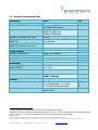
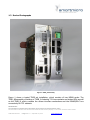
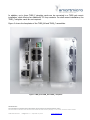
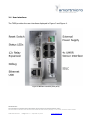
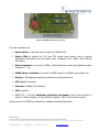
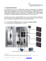
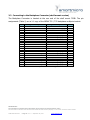
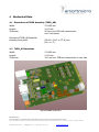
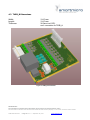
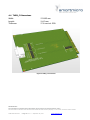
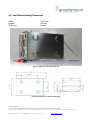
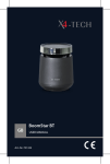
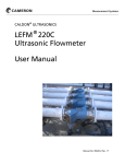
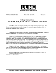
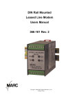
Project Documentation | TMIB Data Sheet Project Number: SMS Project Number: Project Title: Traffic Management Interface Board Keyword(s): TMIB Traffic Management Interface Board NEMA TS1 Loop Detector Output TS2 SDLC Date: September 18, 2015 Document: TMIB Data Sheet.doc PROPRIETARY The information contained in this document may be subject to change without notice. The information contained in this document shall remain the sole exclusive property of s.m.s smart microwave sensors GmbH. TMIB Data Sheet.doc I Page 1 of 17 I September 18, 2015 www.smartmicro.de 1 Traffic Management Interface Board Data Sheet 1.1 General Information The Smartmicro TMIB (Traffic Management Interface Board) connects up to four UMRR Radar sensors (traffic detectors) to NEMA TS1 or TS2 cabinets (TMIB rack mount version); or to other traffic controllers (TMIB shelf mount version). A TMIB set consists of two cards. The TMIB_AB assembly is the control board plus the interface board. This second board contains all surge and overvoltage protection circuitry for four long cables to four sensors, as it is the typical case on an intersection. One TMIB set can replace up to 16 inductive loops (TS1 usage) / up to 64 inductive loops (TS2 SDLC usage, up to four TS2 BIUs replaced). The data of all four Radar sensors can be accessed conveniently through one single 100BaseTX Ethernet interface. Rack-mount use: In a typical (rack mount) installation, the TMIB consists of two NEMA form factor cards: The TMIB_AB assembly consisting of TMIB_A featuring TS1 loop contacts and status LEDs as well as the TMIB_B, which contains the sensor interface connections and the RS485/SDLC bus connectivity for TS2 cabinets. One TMIB can be connected to up to four “Inductive Loop Detector Unit” slots, replacing 16 inductive loops. In addition, up to three TMIB_C expansion cards may be installed. Each TMIB_C card offers four loop detector outputs. In NEMA TS1 installations they can be used to connect additional relay contacts to the traffic cabinet, because each TS1 card is limited to a maximum of four loop detector outputs. Shelf-mount use: In a typical (shelf mount) installation, the TMIB_AB assembly resides within an enclosure, offering all interfaces to the user. The TMIB is well integrated in smartmicro’s TMC (Traffic Management Configurator) PC software to give the installer a powerful and easy-to-use tool for setup and maintenance. Please note: TMIB_A/B/C are not fully fail-safe devices. While a number of steps have been taken to make sure the devices show a fail-safe behavior, this cannot be assured under all conditions. The connected sensors (detectors) do not have 100% detection rate or zero false alarm rate (see data sheet). In case of communication problems, sensor failure, TMIB_A/B/C failure in part or in whole, under certain condition a non-fail-safe behavior may occur. PROPRIETARY The information contained in this document may be subject to change without notice. The information contained in this document shall remain the sole exclusive property of s.m.s smart microwave sensors GmbH. TMIB Data Sheet.doc I Page 2 of 17 I September 18, 2015 www.smartmicro.de 1.2 General Performance Data Parameter Connectivity Supported traffic detectors Supported outputs / interfaces Number of detectors per TMIB Number of virtual loops for NEMA TS2 Number of loops replaced for NEMA TS1 (4 detector slots used) NEMA TS2 Detector BIUs Environmental Ambient Temperature Humidity Shock Vibration Mechanical Weight TMIB_AB Weight TMIB_C Dimensions Model No. General Power Supply Form factor Value Unit Smartmicro UMRR-0Axxxx with RS485/CAN output NEMA TS1 loop detector outputs NEMA TS2 SDLC bus 100Base-TX Ethernet Up to 4 Up to 16 per attached UMRR sensor Up to 64 total Up to 161 Up to 4 (Detector BIU 8 thru 11) NEMA NEMA NEMA NEMA TS2 TS2 TS2 TS2 compliant2 compliant compliant compliant 360 / 12,7 130 / 4.59 See section 4 g / oz TMIB_AB-00xxyy TMIB_C-00xxyy 10 ... 30 <2.5 (operational) / <1.3 (idle) 3.7 for each connected sensor NEMA TS1 / TS2 Inductive Loop Detector Unit V DC W W 1 TMIB_C Extension cards required for more than 4 loop detector outputs. Batteries may have a reduced temperature range from -20°C to +70°C, the buzzer has a reduced temperature range of -30°C to +70°C. These constraints do not limit normal operation of the TMIB. 2 PROPRIETARY The information contained in this document may be subject to change without notice. The information contained in this document shall remain the sole exclusive property of s.m.s smart microwave sensors GmbH. TMIB Data Sheet.doc I Page 3 of 17 I September 18, 2015 www.smartmicro.de 1.3 Device Photographs Figure 1: TMIB_AB assembly. Figure 1 shows a typical TMIB set installation, which consists of two NEMA cards: The TMIB_AB assembly consisting of TMIB_A featuring TS1 loop contacts and status LEDs as well as the TMIB_B, which contains the sensor interface connections and the RS485/SDLC bus connectivity for TS2 cabinets. PROPRIETARY The information contained in this document may be subject to change without notice. The information contained in this document shall remain the sole exclusive property of s.m.s smart microwave sensors GmbH. TMIB Data Sheet.doc I Page 4 of 17 I September 18, 2015 www.smartmicro.de In addition, up to three TMIB_C daughter cards can be connected to a TMIB rack mount installation, each offering four additional TS1 loop contacts. For shelf mount installations, the TMIB_C daughter cards are not required. Figure 2 shows the faceplates of the TMIB_AB and TMIB_C assemblies. Figure 2: TMIB_A and TMIB_B and TMIB_C faceplates. PROPRIETARY The information contained in this document may be subject to change without notice. The information contained in this document shall remain the sole exclusive property of s.m.s smart microwave sensors GmbH. TMIB Data Sheet.doc I Page 5 of 17 I September 18, 2015 www.smartmicro.de 2 Features and Applications 2.1 Intersection Applications NEMA cabinets are typically used to control actuated intersections. They observe the current traffic flow through a set of loop detectors and adopt the red and green phases of the traffic lights accordingly. While loop detectors are dependable and robust, they are also cost and service intensive. UMRR traffic detectors offer cost effective and seamless loop replacement through non-invasive radar technology. In order to connect them to NEMA TS1 or TS2 cabinets, the TMIB is used, which is installed into the detector rack. 2.1.1 NEMA TS1 Installations For NEMA TS1 installations, loop detector outputs are emulated through opto-isolators. The TMIB_AB cards provide four loop detector outputs. Up to 16 loops total can be replaced using TMIB_AB and additional TMIB_C daughter cards - if multiple UMRR-0A sensors shall be connected to one TMIB. 2.1.2 NEMA TS2 Installations For NEMA TS2 installations, all vehicle detections are transmitted over the SDLC serial link. Therefore only the TMIB itself (TMIB_AB assembly) is needed. Up to four Detector BIUs are supported with a total of 64 virtual loops. 2.1.3 Interfaces to Traffic Management Control systems The TMIB offers on board 100Base-TX Ethernet interface for data retrieval and integration into Traffic Management Control systems. 2.2 General purpose applications A shelf mount version offers the loop detector outputs and digital data interfaces in a boxed design – to support a variety of applications. 2.3 On-board diagnostics (BIT) The TMIB has extensive means of onboard diagnostics through watchdog elements and LEDs on the front panel. General function can be instantly overlooked by Power Good, Heartbeat and Failure LEDs. Detailed diagnostics can be retrieved through data interfaces. Signaling of error conditions can be adapted to customer requirements. PROPRIETARY The information contained in this document may be subject to change without notice. The information contained in this document shall remain the sole exclusive property of s.m.s smart microwave sensors GmbH. TMIB Data Sheet.doc I Page 6 of 17 I September 18, 2015 www.smartmicro.de 2.4 User interfaces The TMIB provides the user interfaces displayed in Figure 3 and Figure 4. Figure 3: TMIB User interfaces (front panel) PROPRIETARY The information contained in this document may be subject to change without notice. The information contained in this document shall remain the sole exclusive property of s.m.s smart microwave sensors GmbH. TMIB Data Sheet.doc I Page 7 of 17 I September 18, 2015 www.smartmicro.de Figure 4: TMIB User interfaces (rear panel) The user interfaces are: Reset Switch to allow the user to reset the TMIB device Status LEDs to display the TS1 and TS2 virtual loops states; also to provide diagnostics information such as Power Good, Heartbeat, Error states, SDLC Activity and others. Relay Expansion to connect to TMIB_C Relay Expansion cards (loop detector output channels 5 .. 16). UMRR Sensor Interface to connect to UMRR sensors via RS485 (see section 3.2). Debug for Debugging purposes by smartmicro trained personnel. SDLC Port 1 connector. Ethernet (100Base-TX) interface. USB connector. NEMA TS1 / TS2 style backplane multipoint pin header (rack mount version) or Access to Power Supply / 4x loop detector outputs / SDLC (shelf mount version). Please refer to the TMIB User Manual for detailed functional description. PROPRIETARY The information contained in this document may be subject to change without notice. The information contained in this document shall remain the sole exclusive property of s.m.s smart microwave sensors GmbH. TMIB Data Sheet.doc I Page 8 of 17 I September 18, 2015 www.smartmicro.de 3 Connection Scheme The TMIB connects to up to four UMRR traffic detectors. It provides them with adequate supply voltage (sourced by the power supply terminal block at the TMIB front panel) and reads the data transmitted from or to all four sensors via CAN bus or RS485 data stream. To communicate with NEMA TS1 traffic controllers, the TMIB activates all loop detector outputs corresponding to triggered detection zones defined in the UMRR. In order to support NEMA TS2 systems, the TMIB also sends all assigned loop calls over a SDLC serial link. The data from the four connected UMRR sensors can be retrieved through 100Base-TX Ethernet interface. Also the setup (alignment, placing of virtual loops etc.) of all four sensors can be conveniently accomplished through the one single Ethernet port. 3.1 Connecting four UMRR sensors to a controller through the TMIB The connection scheme is displayed Figure 5 in below. Figure 5: Connecting four UMRR sensors to a controller through the TMIB PROPRIETARY The information contained in this document may be subject to change without notice. The information contained in this document shall remain the sole exclusive property of s.m.s smart microwave sensors GmbH. TMIB Data Sheet.doc I Page 9 of 17 I September 18, 2015 www.smartmicro.de 3.2 Connecting UMRRs The homerun cable of each UMRR-0A traffic sensor is fed to a patch panel inside the traffic cabinet, where it is wired to a short Cat5 cable with RJ-45 connector, which plugs in directly into the sensor interface block of the TMIB_B board. The standard version uses duplicated power lines for optimal sensor supply on long, low cross-section cables. The pin-out of the TMIB and the corresponding junction box (JBOX) at the sensor is depending on the UMRR sensor you use (-0A or -0F) and the RS485 interface (half- or full-duplex). See the following tables for more details. RJ-45 pin Signal description JBOX pin 1 2 3 4 5 6 7 8 Sensor RS485 TX/RX L Sensor RS485 TX/RX H CAN H SENSOR_VCC SENSOR_GND CAN L Sensor RS485 TX H Sensor RS485 TX L 4 3 1 5 6 2 NC NC Wire color EIA/TIA 568B (World) White/orange Orange White/green Blue White/blue Green White-brown Brown Wire color EIA/TIA 568A (Europe) White-green green White-orange Blue White-blue Orange White-brown Brown Table 1: TMIB Half duplex version pin-out (UMRR-0A half-duplex RS485) RJ-45 pin Signal description JBOX pin 1 2 3 4 5 6 7 8 Sensor RS485 TX/RX L Sensor RS485 TX/RX H CAN H SENSOR_VCC SENSOR_GND CAN L Sensor RS485 TX H Sensor RS485 TX L 5 6 11 8 7 12 NC NC Wire color EIA/TIA 568B (World) White/orange Orange White/green Blue White/blue Green White-brown Brown Wire color EIA/TIA 568A (Europe) White-green green White-orange Blue White-blue Orange White-brown Brown Table 2: TMIB Half duplex version pin-out (UMRR-0F half-duplex RS485) RJ-45 pin Signal description JBOX pin 1 2 3 4 5 6 7 8 Sensor RS485 RX L Sensor RS485 RX H CAN H SENSOR_GND SENSOR_VCC CAN L Sensor RS485 TX H Sensor RS485 TX L 5 6 11 8 7 12 4 3 Wire color EIA/TIA 568B (World) White/orange Orange White/green Blue White/blue Green White-brown Brown Wire color EIA/TIA 568A (Europe) White-green green White-orange Blue White-blue Orange White-brown Brown Table 3: TMIB Full duplex version pin-out (UMRR-0F full-duplex RS485) PROPRIETARY The information contained in this document may be subject to change without notice. The information contained in this document shall remain the sole exclusive property of s.m.s smart microwave sensors GmbH. TMIB Data Sheet.doc I Page 10 of 17 I September 18, 2015 www.smartmicro.de 3.3 Connecting to the Backplane Connector (shelf mount version) The Backplane Connector is located at the rear end of the shelf mount TMIB. The pin assignments (Table 1) are a 1:1 copy of the NEMA TS1 / TS2 backplane multipoint socket. Pin 1 2 3 4 5 6 7 8 9 10 11 12 13 14 15 16 17 18 19 20 21 22 Signal description N.C. N.C. N.C. N.C. N.C. N.C. Channel 1 Status Output N.C. N.C. N.C. N.C. N.C. N.C. N.C. N.C. Channel 3 Status Output N.C. N.C. N.C. Channel 2 Status Output N.C. Channel 4 Status Output Signal description Logic Ground Detector Unit DC Supply External Reset N.C. N.C. Channel 1 Output (+) Channel 1 Output (-) N.C. N.C. Chassis Ground N.C. N.C. N.C. N.C. Channel 3 Output (+) Channel 3 Output (-) N.C. N.C. Channel 2 Output (+) Channel 2 Output (-) Channel 4 Output (+) Channel 4 Output (-) Pin A B C D E F H J K L M N P R S T U V W X Y Z Table 1: Backplane Connector Pin Assignments PROPRIETARY The information contained in this document may be subject to change without notice. The information contained in this document shall remain the sole exclusive property of s.m.s smart microwave sensors GmbH. TMIB Data Sheet.doc I Page 11 of 17 I September 18, 2015 www.smartmicro.de 4 Mechanical Data 4.1 Dimensions of TMIB Assembly (TMIB_AB) Width: Length: Thickness: Size limit of TMIB_AB Assembly including front panel: 174.625 mm 114.3 mm 56.2mm incl. PCB with components, excl. front panel. (59.44 x 114.3 x 177.8) mm (W x L x T). 4.2 TMIB_A Dimensions Width: Length: Thickness: 174.625 mm 114.3 mm 34.1 mm incl. PCB and components on rear side. Figure 6: TMIB-A circuit board PROPRIETARY The information contained in this document may be subject to change without notice. The information contained in this document shall remain the sole exclusive property of s.m.s smart microwave sensors GmbH. TMIB Data Sheet.doc I Page 12 of 17 I September 18, 2015 www.smartmicro.de 4.3 TMIB_B Dimensions Width: Length: Thickness: 114.3 mm 114.3 mm 26.9mm incl. PCB, excl. connection to TMIB_A. Figure 7: TMIB_B circuit board PROPRIETARY The information contained in this document may be subject to change without notice. The information contained in this document shall remain the sole exclusive property of s.m.s smart microwave sensors GmbH. TMIB Data Sheet.doc I Page 13 of 17 I September 18, 2015 www.smartmicro.de 4.4 TMIB_C Dimensions Width: Length: Thickness: 174.625 mm 114.3 mm 17.6 mm incl. PCB. Figure 8: TMIB_C circuit board PROPRIETARY The information contained in this document may be subject to change without notice. The information contained in this document shall remain the sole exclusive property of s.m.s smart microwave sensors GmbH. TMIB Data Sheet.doc I Page 14 of 17 I September 18, 2015 www.smartmicro.de 4.5 Shelf Mount Housing Dimensions Width: Length: Thickness: 119.5 mm 200 mm 64 mm Figure 9: TMIB_AB in Shelf Mount Housing Figure 10: Dimensions of Shelf Mount Housing PROPRIETARY The information contained in this document may be subject to change without notice. The information contained in this document shall remain the sole exclusive property of s.m.s smart microwave sensors GmbH. TMIB Data Sheet.doc I Page 15 of 17 I September 18, 2015 www.smartmicro.de 5 Important Legal Disclaimer Notice All Product, Product specifications and data in this project documentation are subject to change without notice to improve reliability, function, design or otherwise. The statements, technical information and recommendations contained herein are believed to be accurate as of the date hereof. Smartmicro disclaims any and all liability for any errors, inaccuracies or incompleteness contained in this datasheet or in any other disclosure relating to the Product. To the extent permitted by applicable law, Smartmicro disclaims (i) any and all liability arising out of the application or use of the Product or the data contained herein, (ii) any and all liability of damages exceeding direct damages, including - without limitation – indirect, consequential or incidental damages, and (iii) any and all implied warranties, including warranties of suitability of the Product for a particular purpose. Statements regarding the suitability of Products for certain types of applications are based on Smartmicro’ knowledge of typical requirements that are often placed on Smartmicro’ Products in generic/general applications. Such statements are, however, not binding statements about the suitability of Products for a particular/specific application. It is the customer/user’s own responsibility to validate that the Product with the specifications described herein is suitable for use in its particular/specific application. Parameters and performance of the Products may due to particular/specific applications and due to particular/specific surroundings deviate from the statements made herein. Therefore, it is important that customer/user has thoroughly tested the Products and has understood the performance and the limitations of the Products before installing the Products for the final applications or before commercialization. Although Products are well optimized to be used for the intended applications stated herein, it must also be understood by the customer/user that the detection probability may not be 100 % and the false alarm rate may not be zero. The information provided herein, relates only to the specific Product designated and may not be applicable when such Product is used in combination with other materials or in any process not defined herein. All operating parameters, including typical parameters, must be validated for each customer application by the customer/user’s technical experts. Customers using or selling Smartmicro products not expressly indicated for use in such applications do so at their own risk. This Product specification or data sheet does not expand or otherwise modify Smartmicro terms and conditions of purchase, including but not limited to the warranty expressed therein. Except as expressly indicated in writing by Smartmicro, the Products are not designed for use in medical, life-saving, or life-sustaining applications or for any other application in which the failure of the Product could result in personal injury or death. No license, express or implied, by estoppel or otherwise, to any intellectual property rights is granted by this document or by any conduct of Smartmicro Product names and markings noted herein may be trademarks of their respective owners. Please note that the application of the Product may be subject to standards or other regulations that may vary from country to country. Smartmicro does not guarantee that the use of Products in the applications described herein will comply with such regulations in any country. It is the customer/user’s responsibility to ensure that the use and incorporation of Products complies with the regulatory requirements of their markets. If any provision of this Disclaimer is, or is found to be, void or unenforceable under applicable law, that will not affect the validity or enforceability of the other provisions of this Disclaimer. PROPRIETARY The information contained in this document may be subject to change without notice. The information contained in this document shall remain the sole exclusive property of s.m.s smart microwave sensors GmbH. TMIB Data Sheet.doc I Page 16 of 17 I September 18, 2015 www.smartmicro.de 6 Contact Address: smart microwave sensors GmbH In den Waashainen 1 38108 Braunschweig Germany Phone / Fax numbers: Phone: Fax: +49-531-39023-0 +49-531-39023-599 Web / Email address: Web: Email: www.smartmicro.de [email protected] PROPRIETARY The information contained in this document may be subject to change without notice. The information contained in this document shall remain the sole exclusive property of s.m.s smart microwave sensors GmbH. TMIB Data Sheet.doc I Page 17 of 17 I September 18, 2015 www.smartmicro.de