1
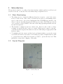
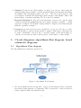
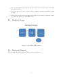
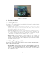
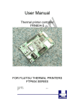
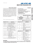
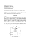
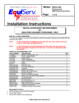
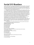
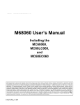
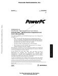
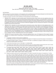
G-Cat: A glove based user interface
Ayesha Mudassir [09007014] [email protected]
Kedar Tatwawadi [09D07022] [email protected]
Supervisor: Dipankar Sarkar
April 17, 2013
Abstract
We plan to have a glove based user-interface similar to the conventional mouse
and keyboard interface. The project would be useful to people with paralytic
disabilities, who can move only some parts of their limbs. The G-Cat might not
be suitable for heavy typing work. But, it is suitable for day-to-day jobs such as
web browsing, accounting etc. which make intermittent use of mouse and keypad.
As the project has intuitive appeal ( hand movements corresponding to mouse
movements, or corresponding to arrow keys) , it would be in general fun to use .
The major electronic components involve Resistive touchpad, accelerometer reed
contact switches etc.
1
Contents
1 Introduction
1.1 Basic Functioning . . . . . . . . . . . . . . . . . . . . . . . . . . . . . . .
1.2 Layout Diagram . . . . . . . . . . . . . . . . . . . . . . . . . . . . . . . .
1.3 Improvemets over past projects . . . . . . . . . . . . . . . . . . . . . . .
3
3
3
4
2 Problem statement
2.1 Basic Functionality Requirements . . . . . . . . . . . . . . . . . . . . . .
4
4
3 Design approach
3.1 Design Approach . . . . . . . . . . . . . . . . . . . . . . . . . . . . . . .
5
5
4 Design of circuit
5
5 Circuit diagrams, algorithmic flow diagram, board
5.1 Algorithmic Flow diagram . . . . . . . . . . . . . .
5.2 Hardware Design . . . . . . . . . . . . . . . . . . .
5.3 Schematic Diagram . . . . . . . . . . . . . . . . . .
5.4 PCB layout . . . . . . . . . . . . . . . . . . . . . .
schematic diagrams
. . . . . . . . . . . .
. . . . . . . . . . . .
. . . . . . . . . . . .
. . . . . . . . . . . .
6 Test procedures
6.1 Test applications . . . . . . . . . . . . . . . . . . . . . . . . . . . . . . .
6.2 Testing/Debugging methods . . . . . . . . . . . . . . . . . . . . . . . . .
6
6
7
7
8
9
9
9
7 Conclusion and suggestions for further improvement.
10
8
11
Major Problems Faced
9 User’s manual
11
10 References
12
2
1
Introduction
The product is aimed to be a Glove based user interface which would act as a Keyboard
as well as a mouse on any OS. The basic functioning is explained below:
1.1
Basic Functioning
1. The tilting motion of hand in different directions is used to control the cursor
motion on the screen. The x and y accelerations are used for determining cursor
speed on the screen. As we have implemented the USB HID type interface, the
cursor location controlling happens via USB report format. The USB report needs
one to specify δx and δy values for the cursor and a flag specifying whether a mouse
key has been pressed.
2. The Resistive touchpad is used as a Keyboard. Based on the x and y voltage
readings one can decide the location of contact. This is used to map a location to
a specific key.The keypress information is sent via USB using an appropriate USB
Report format.
3. To multiplex the the mouse and the keyboard functionalities, we use the z-axis
acceleration from the accelerometer. if z-reading is positive, it implies that we wish
to operate the mouse, while if it is negative, we wish to operate the keyboard. This
physically corresponds to flipping of the palm.
1.2
Layout Diagram
Figure 1: G-Cat Layout
3
1.3
Improvemets over past projects
The project is based on a past EDL project:[Accelerometer based wireless mouse].
http://wel.ee.iitb.ac.in/wel45/public_html/edl09a/dd09.pdf We plan to implement a few improvements and modifications over the past project. Those are:
1. Instead of a mouse simulation in Matlab, we will be implementing a working mouse
model.
2. In addition to the mouse, we would be implementing a basic keyboard. Implementing the system as a HID device ( human interface device) for platform independence.
3. Implementing an error-correcting communication library for PIC18F microcontrollers for low-end ASK modules (similar to virtualWire library for Arduino/
MSP430).
4. The project is based on use of accelerometers, resistive touch pad for user input,
wireless communication for flexibility and implementing the system as a HID (
human interface device) for speed (and OS independence).
2
Problem statement
Using gloves in both the hands , we plan to have a wireless user-interface similar to
the conventional mouse and keyboard interface. The project would be useful to people
with paralytic disabilities, who can move only some parts of their limbs. The GloveUI might not be suitable for heavy typing work. But, we plan to make it suitable for
day-to-day jobs such as web browsing, accounting etc. which make intermittent use of
mouse and keypad. As the project has intuitive appeal ( hand movements corresponding
to mouse movements, or corresponding to arrow keys) , it would be in general fun to use .
2.1
Basic Functionality Requirements
The functionalities of G-cat are:
1. It must function as a Mouse and a Keyboard on any OS.
2. It must be light, elegant and a practically usable device.
3. Making it wireless would be an additional functionality which would make it very
flexible.
4. The power consumption must be low. The system must be in a stand-by mode
when not in use.
5. If wireless , it is desirable to have battery life 3-6 months, or have a rechargeable
battery.
4
3
Design approach
3.1
Design Approach
The design approach which we followed is:
1. Conceptualise a wired proof of concept design.
2. Built the design using off the shelf components
3. Debug and modify the design so that the development boards and modules can be
appropriately replaced .
4. Build a PCB board and implement the circuit on the PCB.
5. Try modifying the design to optimize component usage and manufacturing cost.
4
Design of circuit
Here we present a brief justification of why we used a particular component.
1. Microcontroller: As we need to implement an USB – HID (human interfacing
device) on the receiver side, we had 2 options:
Atmega series: atmega 16,32, dont have native USB support. But there is a vusb library which can be used to convert the atmega microcontroller into a virtual
USB.
PIC 18 series: It has native USB support. We also came across a few projects
which have implemented a HID using PIC18 series (which confirmed the feasibility). Also, as Wel lab has recently developed Aurum development boards based on
PIC18F4550 , it would get us started early on the project.
Link : http://59.181.142.81/uc/pic/index.php
2. accelerometer We needed to choose between analog vs digital accelerometers and
also which IC needs to used. Its always good to use off the shelf components, and
better to use modules as they are easy to interface. Understanding this fact, we
had a look at analog (MMA7631 3-axis accelerometer ,range 2g) as well as digital
accelerometer modules. We found that, for moderate sampling rate requirements
analog accelerometers are much easier to interface, while digital ones are more
useful for higher speeds. Hence we decided to go with digital accelerometers.
3. wireless modules In case of wireless transfer, its very difficult to create a module
in such a short period. Hence, we decided to use modules which are not too
expensive, so that they can be directly incorporated into the product. The 433 MHz
ASK modules are ideal, as even though they dont have error correcting capabilities,
they are cheap 300 Rs).
5
4. Switches For the mouse click switches, we had a few options, either using the
standard push button switches on index and middle finger and pressing them using
the thumb. But, this might require some force . The other option was choosing
reed switches on middle and index fingers and a magnet on the thumb. This would
then facilitate contactless switching. We chose the reed switches.
5. Keypad/Touchpad For The keyboard interfacing, we had a few options: using
a 4x4 dot matrix and multiplexing the keys, using a resistive touchpad , or using
capacitive touchpad. We thought of using resistive touchpad as it is much cheaper
than the capacitive touchpad.
6. Layout the product layout was very essential for our project. We chose to place
the PIC18F microcontroller circuit and the touchpad on the wrist so that there are
no issues of flexibility of motion due to excessive weight. As shown in figure [1],
only the accelerometer module would be placed on the hand to reduce weight.
5
Circuit diagrams, algorithmic flow diagram, board
schematic diagrams
5.1
Algorithmic Flow diagram
The Algorithmic flow diagram is given below:
Figure 2: Algorithmic flow diagram
1. We decide whether mouse is being used , or keyboard is being used based on whether
the palm is facing upwards or downwards. This corresponds to z-axis acceleration
being compared with some threshold value.
6
2. If we are using the mouse, then we use the x and y axis accelerations to determine
the cursor motion.
3. For Keyboard, the location of press on the touchpad determines which key is being
pressed.
4. Finally this data is send in an appropriate USB report format so that the coputer
recognizes the devise as a valid HID device.
5.2
Hardware Design
Figure 3: Algorithmic flow diagram
5.3
Schematic Diagram
The schematic diagram and the PCB layout are shown below.
7
1
PWRSEL
1
2
3
GND
VBUS
DD+
VDDIN
C4
IN
VDD
OUT
C5
ADJ
GND
R2
GND
VBUS
DD+
IC2
REG3.3
R12
1
2
RESET
/RESET
3
4
BOOT
GND
RB4
RB5
RB6
RB7
RA0
RA1
RA2
RA3
C6
GND
44
43
42
41
40
39
38
37
36
35
34
33
32
31
30
29
28
27
26
25
24
23
RC6
D+
D-
JP6
D3
D2
D1
D0
C3
RC6/TX/CK
RC7/RX/DT/SDO
RC5/D+/VP
RD4/SPP4
RC4/D-/VM
RD5/SPP5/P1B
RD3/SPP3
RD6/SPP6/P1C
RD2/SPP2
RD7/SPP7/P1D
RD1/SPP1
VSS
RD0/SPP0
VDD
VUSB
RB0/AN12/INT0/LFT0/SDI/SDA
RC2/CCP1/P1A
RB1/AN10/INT1/SCK/SCL
RC1/T1OSI/ICCP2/UOE
RB2/AN8/INT2/VMO
NC/ICPORTS
RB3/AN9/CCP2/VPO
NC/ICRST/IVVPP
NC/ICCK/ICPGC
RC0/TIOSO/T13CKI
NC/ICDT/ICPGD
RA6/OSC2/CLKO
RB4/AN11/KBI0/CSSPP
OSC1/CLKI
RB5/KBI1/PGM
VSS
RB6/KBI2/PGC
VDD
RB7/BKI3/PGD
RE2/AN7/OESPP
MCLR/VPP/RE3
RE1/AN6/CK2SPP
RA0/AN0
RE0/AN5/CK1SPP
RA1/AN1
RA5/AN4/SS/HLVDIN/C2OUT
RA2/AN2/VREF-/CVREF
RA4/T0CKI/CIOUT/RCV
RA3/AN3/VREF+
RC2
RC1
RC0
Q1
1
2
3
4
5
6
7
8
9
10
11
12
13
14
15
16
17
18
19
20
21
22
RA6
C1 C2
15
16
1
RC7
D4
D5
D6
D7
GND
VDD
RB0
RB1
RB2
RB3
R1
VDDIN
R3
1
2
3
IC1
LCD_CONNECTOR
1
GND
2
VDDIN
3
BLT D7
4
D6
5
D5
6
D4
7
D3
8
D2
9
D1
10
D0
11
EN
12
R/W
13
RS VDD
14
COM
3
4
2
RB0
RB1
RB2
RB3
RB4
RB5
RB6
RB7
VDD
GND
COM
USB
S4
PWR
2
3
4
JP5
2
VEXT
1
GND
4
3
2EXTPWR
1 GND
R4
R5
R6
R7
R8
R9
R10
R11
VDD
R13
L2
L1
ON
10
9
8
7
6
5
4
3
2
1
5
6
7
8
L4
GND L3
GND
GND
VDD
EN
R/W
RS
RA5
RA4
PIC18F
RB5
RB6
RB7
GND
VDD
/RESET
6
5
4
3
2
1
DEBUG
29-May-12 15:49:12 f=1.20 C:\Documents and Settings\Administrator\My Documents\eagle\Aurum_v12\aurum_v2_0.sch (Sheet: 1/1)
Figure 4: G-Cat schematic
5.4
PCB layout
Figure 5: PCB layout
8
VDD
RC6
RC7
GND
RA5
RA3
RA1
GND
1
3
5
7
9
11
13
15
2
4
6
8
10
12
14
16
RC0
RC1
RC2
RA6
RA4
RA2
RA0
VDD
Figure 6: board image
6
Test procedures
6.1
Test applications
We conducted a few example applications in which the G-Cat would be useful and which
would rank as good test examples:
1. Solitaire using G-cat We demonstrated how the game of solitaire can be played
using the G-Cat. There were some issues like the smoothness of mouse motion and
the thresholds applied for the cursor motion.
2. Roadrash using G-cat For playing roadrash using G-Cat, we mapped the arrow
keys to accelerometer motion. i.e: a left tilt of accelerometer corresponds to the
left arrow key and thus a left turn in the roadrash game etc. This made the game
controls much more intuitive and very similar to that of a joystick.
3. Web browsing As G-cat is meant to be used for daily work on a computer, web
browsing is one such example. We demonstrated webpage scrolling by again mapping the arrow keys. One needs a key to multiplex the operations of accelerometer
as a mouse and as arrow keys.
6.2
Testing/Debugging methods
Here we note down some procedures which we found very useful while debugging or
testing a component of the system.
1. Accelerometer Whenever any problem was encountered with Accelerometer, the
easiest way is to test it with arduino module. The serial out facility makes it very
easy to test and debug if there is any problem . The testing codes can be found in
the documentation folder.
9
2. Touchpad We faced significant problems with the touchpad. Whenever touchpad
creates problems, the convenient way is to use a LCD and to print the ADC value
onto it.
3. PIC18 Most of the microcontroller problems which we faced were due to corruption
of bootloader on the PIC18f4550. In such cases, keep a PICKIT handy, so that the
bootloader can be again put onto the microcontroller.So, if the MuC shies away
from going into boot mode, just install the bootloader again and it will work fine.
4. USB Mouse To test whether basic USB HID functionality is working . The sample
4550m ouse in the documentation folder can be executed. This sample program
moves the mouse in circular motion.
Figure 7: Testing Setup
7
Conclusion and suggestions for further improvement.
The project has significant scope for further development:
1. adding flex sensors, the product can be converted into a device for mute-sign language to english so that the mute people can easily communicate in the society.
2. Hand Gestures can be used to map some common functionalities like mapping a
circular rotation of hand to increase /decrease in volume.
3. Some parts of the project indivisually can be modified eg: the ASK module wireless
part can be used to transmit wireless data to computer using cheap modules.
10
8
Major Problems Faced
Here we list down some of the major problems which we faced while we were working on
the project and which can save the time of people who work on similar projects in the
future.
1. In the case of Aurum board ( or any other board using USB to program the MuC)
, There is a linker file which needs to be added to the Mplab project. also, a vector
remapping code needs to inserted. Failing to do this would make the microcontroller
code not get burnt on the MuC / the code would not work.
2. Interfacing wireless modules can be tricky business.
3. We faced major problems with the Touchpad. The non-availability of weak pull
ups on port A of PIC18, makes it difficult to interface a resistive touchpad directly
with the microcontroller.
9
User’s manual
This is a short user manual for using the G-Cat. The functionality details are as follows:
1. Hand tilts refer to cursor motion on the screen.
2. One can use the touchpad for keypresses. As for the current implementation, only
a few keys have been mapped onto the touchpad.
3. The switch presses correspond to left and right clicks.
1. The first step is installing the bootloader on the PIC18 microcontroller on the
board. Use PICKIt to install the bootloader.
2. Compile the project blink using C18 compiler and load the hex file onto the microcontroller using the HIDBootloader.exe. This test program blinks the the LED at
port RA1. This would confirm that the bootloader was succesfully installed.
3. To implement the actual application, compile the 4550M ouseK ey1 project and burn
the hex file generated. If everything works well, the application has been loaded
onto the board.
4. In case the previous step doesnt work out well, first try compiling and running
4550M ouseproject. This project runs only the mouse using the accelerometer readings. Still if the problem persists refer to the debugging section of the report (first
debug the problems on the Aurum development board).
11
10
References
1. PIC18f4550 datasheet www.microchip.com
2. Aurum board user manual 59.181.142.81/
3. USB Serial bus Device class definition HID www.usb.org/developers/devclass_
docs/HID1_11.pdf
4. VirtualWire library for wireless communication www.virtualwire.in
5. Microchip Application Library
6. USB HID device usage table www.usb.org/developers/devclass_docs/Hut1_11.
pdf
12