1
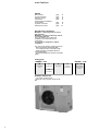
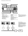
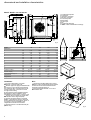
M I C R O S Y S T E M
SERIE
Q-FLOW
MCAE-MHAE: 115 ÷ 1 2 7
Condensing units and reversible condensing units,
air cooled with axial fans.
Range equipped with hermetic scroll compressors.
K11071-GB ed. 2
T E C H N I C A L C ATA L O G U E
main features
INDEX
Main features
Technical features
Electronic control
Performance
Dimensional and installation
characteristics
Hydraulic connection
Electrical connection
page
page
page
page
2
4
5
6
page
page
page
8
9
11
Standard use conditions
MCAE are condensing units air cooled
with axial fans.
MHAE are reversible condensing units air
cooled with axial fans.
They are suitable in air conditioning
installations connected with remote
evaporators.
The machine is designed for outdoor
installation.
The units comply with the following Directives:
• Machine Directive 89/392/CEE (MD);
• Low Voltage Directive 73/23/CEE (LVD);
• Electromagnetic Compatibility Directive
89/336/CEE (EMC);
• Pressurised Equipment Directive 97/23/CEE
(PED).
Code guide
“RANGE” code
“MODEL” code
M
C
A
E
115 - 127
Condensing
unit
Cooling only
Air cooled
Hermetic
compressors
Approximate
cooling capacity
(in kW)
H
Heat pump
Example: MCAE 122
● Air cooled condensing unit.
● Nominal cooling capacity: about 22 kW.
2
main features
Features
Electrical board
● Chassis made of Peraluman panels; base
in galvanised sheet steel; sound proofed
compressor chamber.
● Hermetic Scroll rotary compressor
complete with internal overload protection.
● Air side exchanger composed of coil with
copper pipes and aluminium fins, complete
with protection grille.
● Axial fan featuring external rotor, internal
overload cut-out, complete with protective
grille.
● Flare refrigerant couplings with valve.
● Refrigerant circuit with mild copper tubes
and silver alloy welding. Complete with filter
drier, charge connections, safety high
pressure switch with manual reset (in
compliance with Directive 97/23/CEE (PED),
safety low pressure switch with automatic
reset, control pressure switch for winter
operation (for MHAE 115), crankcase heater,
liquid-humidity indicator, settable safety
valves, thermostatic expansion valve (for
MHAE), cycle inversion valve (for MHAE),
non-return valve (for MHAE), liquid receiver
and gas separator with safety valve (for
MHAE).
● Unit with IP24 protection grade.
● Unit complete with:
• ductable condensate discharge (for MHAE);
• R 407C refrigerant charge foreseen for
length of gas and liquid lines each of 7 m.
● Electrical board can be accessed from front
panel compliant with IEC standards, complete
with:
• main power supply switch with interlocking
safety door isolator;
• electrical wiring arranged for power supply
400V-3ph-50Hz+N;
• auxiliary circuit power supply
230V-1ph-50Hz derived from main power
supply;
• phase sequence controller;
• automatic switches for protection of
compressor and auxiliary circuit;
• power contactor for compressor;
• user interface terminal board ;
• removable machine controls.
● Programmable microprocessor electronic
board handled by the keyboard inserted in the
machine. .
The board performs the following functions:
• adjustment and control of cycle inversion
(for MHAE); of the safety delays; of the
compressor hour-run-meter; of the defrost
cycles (for MHAE); of all the functions that
control the working interventions of the unit
devices;
• complete protection of the unit, possible cut
off of the machine and display of the active
alerts;
• display of operating devices by LED; of the
heat pump or chiller operation by LED, (for
MHAE); of defrosting in progress by LED (for
MHAE);
• self-diagnosis with continual checking of the
machine oeprational status.
● Advanced functions:
• arranged for serial connection, with RS485
outlet for logical dialogue with building
automation, centralized systems and
supervision networks.
• computer assisted unit testing.
Accessories supplied loose
● KSA - Rubber antivibration mountings.
● KFI - Low ambient control for continuous
control of the fan rotation speed down to
outdoor air temperatures of –10°C during
chiller operation, for ambient air temperatures
up to 30°C during heat pump.
● KIS - RS 485 serial interface for
interconnection with distributed intelligent
systems for integrated building automation.
● KCH - RS232 hardware key to be
connected to supervision systems, to combine
with one or more KIS serial interface modules
in centralized unit management system.
3
technical features
MODEL MCAE
115
118
122
127
14,7
17,6
21,8
26,3
49
50
51
52
Technical data
Nominal cooling capacity (*)
kW
Sound pressure (***)
dB(A)
Hermetic Scroll compressor
n.
1
1
1
1
Fan
n.
1 x 0,38
1 x 0,38
1 x 0,38
1 x 0,38
Fan nominal air flow
L/h
5.900
5.500
6.300
6.000
R 407C refrigerant charge
kg
4,25
5,95
6,40
8,55
Polyester oil charge
L
1,90
1,60
3,15
3,15
(*) At the following conditions: condenser inlet
air temperature 35°C; suction satured gas
temperature 7°C.
(**) At the following conditions: evaporator
inlet air temperature 6°C W.B.; dew point
50°C.
(***) The sound pressure level in dB(A) refers
to readings taken 5 m from the unit with a
directionality factor equal to 2 (reduce this
value by 3 dB(A) to obtain the open field
value).
Electrical data
Total absorbed power (*)
kW
4,91
5,65
7,41
8,92
Power supply
V-ph-Hz
400-3-50
400-3-50
400-3-50
400-3-50
Auxiliary power supply
V-ph-Hz
230-1-50
230-1-50
230-1-50
230-1-50
Nominal current
A
8,7
10,4
13,2
17,2
Max. current
A
11,4
13,0
15,7
19,3
Starting current
A
66
74
98
130
H
Dimensions
Length
L mm
1.326
1.326
1.716
1.716
Height
H mm
1.230
1.230
1.230
1.230
Depth
P mm
527
527
615
615
115
118
122
127
L
MODEL MHAE
Technical data
Nominal heating capacity (**)
kW
15,8
19,9
24,5
29,9
Nominal cooling capacity (*)
kW
14,7
17,8
21,8
26,3
Sound pressure (***)
dB(A)
49
50
51
52
Hermetic Scroll compressor
n.
1
1
1
1
Fan
n.
1 x 0,38
1 x 0,38
1 x 0,38
1 x 0,38
Fan nominal air flow
L/h
5.900
5.500
6.300
6.000
R 407C refrigerant charge
kg
6,15
7,55
8,45
10,45
Polyester oil charge
L
1,90
1,60
3,15
3,15
Electrical data
Total absorbed power (**)
kW
5,12
5,53
7,23
8,40
Power supply
V-ph-Hz
400-3-50
400-3-50
400-3-50
400-3-50
Auxiliary supply
V-ph-Hz
230-1-50
230-1-50
230-1-50
230-1-50
Nominal current
A
9,2
10,1
12,4
16,2
Max. current
A
11,4
13,0
15,7
19,3
Starting current
A
66
74
98
130
Dimensions
Length
L mm
1.326
1.326
1.716
1.716
Height
H mm
1.230
1.230
1.230
1.230
Depth
P mm
527
527
615
615
operation limits
Cooling cycle:
● Condenser inlet air temperature:
• version MCAE - MHAE 20°C - 43°C D.B.
Heating cycle:
● Evaporator inlet air temperature:
• version MHAE –5°C - 20°C D.B.
4
P
microprocessor electronic control
Keyboard and display description
4
5
mode
6
3
set
7
2
on
off
8
1
fig. 1
1 = DISPLAY:
it displays the value of all the
parameters, the codes of the possible
alarms and the status of all the
resources.
2 = ON/OFF, RESET - DOWN key:
it allows to switch ON, OFF and the reset
of possible alarms of the unit.
Furthermore allows to scroll down the
value of the parameters.
3 = MODE - UP key:
it allows to scroll up the
value of the parameters.
4 = Summer LED:
it indicates that the unit is working in
cooling cycle.
5 = Winter LED:
it indicates that the unit is working in
heating cycle.
6 = Compressor LED:
it indicates that the compressor are ON
or that a delay is in progress.
7 = Defrosting LED (only active on MHAE):
it indicates that the unit is in the
defrosting mode.
8 = Power supply LED:
it indicates the presence of power supply
in the unit.
N.B.
The keyboard with display makes it possible
to view all process variables of the unit.
For technical service, it makes it possible, with
a password, to access the unit management
parameters (access allowed only for
authorized personnel).
KIS serial interface RS 485 (accessory)
Serial connection
fig. 2
KIS
KIS
The units are equipped with an electronic
controller, that is compatible with an external
system through a serial communication line.
The communication protocol allows the
access to all the functions of the unit, such as:
● setting all the values accessible by the
keyboard;
● reading all the process variables of the
digital as well as analogue inputs and outputs;
● reading the various alarm codes and if
necessary resetting them;
● reading all programming parameters or
changing some of them.
KIS
KCH
PERSONAL
COMPUTER
5
performance
Cooling capacity MCAE-MHAE 115
Ts (°C)
Ta/B.S.(°C)
20
QF
kW
17,38
18,09
20,09
5
7
10
25
P
kW
3,48
3,49
3,52
QF
kW
16,29
17,00
19,01
30
P
kW
3,90
3,90
3,93
QF
kW
15,18
15,91
17,89
35
P
kW
4,38
4,38
4,40
QF
kW
14,04
14,70
16,75
40
P
kW
4,90
4,91
4,92
QF
kW
12,87
13,55
15,59
43
P
kW
5,48
5,49
5,50
QF
kW
12,16
12,85
14,87
P
kW
5,83
5,83
5,89
Heating capacity MHAE 115
Ta/B.S. (°C)
UR (%)
40
–5
0
5
7
10
15
20
QT
kW
10,63
13,20
15,67
17,59
18,25
20,71
23,29
90
90
85
85
80
80
80
Tc (°C)
50
45
P
kW
3,78
3,81
3,85
3,86
3,87
3,91
3,93
QT
kW
10,17
12,74
15,21
17,14
17,79
20,25
22,83
P
kW
4,21
4,27
4,31
4,33
4,35
4,36
4,38
QT
kW
9,74
12,32
14,78
15,80
17,36
19,82
22,40
55
P
kW
5,02
5,04
5,10
5,12
5,13
5,17
5,20
60
QT
kW
–
11,89
14,35
15,38
16,93
19,39
21,97
P
kW
–
5,59
5,68
5,71
5,74
5,77
5,81
QT
kW
–
–
14,06
15,09
16,64
19,11
21,68
P
kW
–
–
5,93
5,96
5,99
6,03
6,05
Cooling capacity MCAE-MHAE 118
Ts (°C)
Ta/B.S.(°C)
20
QF
kW
20,73
21,50
24,00
5
7
10
25
P
kW
3,99
4,00
4,01
QF
kW
19,46
20,24
22,74
30
P
kW
4,49
4,49
4,50
QF
kW
18,18
18,97
21,46
35
P
kW
5,03
5,03
5,04
QF
kW
16,89
17,60
20,16
40
P
kW
5,65
5,65
5,66
QF
kW
15,58
16,28
18,86
43
P
kW
6,37
6,37
6,38
QF
kW
14,79
15,53
18,06
P
kW
6,76
6,82
6,82
Heating capacity MHAE 118
Ta/B.S. (°C)
UR (%)
40
–5
0
5
7
10
15
20
P
QF
QT
6
90
90
85
85
80
80
80
QT
kW
14,05
16,95
19,82
20,80
23,00
26,16
29,31
Tc (°C)
50
45
P
kW
4,54
4,58
4,60
4,60
4,61
4,62
4,62
= Total absorbed electrical power
= Cooling capacity
= Heating capacity
QT
kW
13,50
16,40
19,27
22,07
22,46
25,61
28,76
Ta/B.S. =
Tc
=
Ts
=
UR
=
P
kW
4,66
4,71
4,80
4,81
4,81
4,82
4,84
QT
kW
12,91
15,81
18,68
19,90
21,87
25,02
28,17
55
P
kW
5,51
5,51
5,52
5,53
5,54
5,54
5,55
Dry bulb ambient temperature
Dew point
Suction satured gas temperature
Relative humidity
QT
kW
–
15,39
18,25
19,51
21,44
24,59
27,74
60
P
kW
–
6,05
6,06
6,06
6,07
6,07
6,08
QT
kW
–
–
17,67
20,77
20,86
24,01
27,16
P
kW
–
–
6,88
6,94
6,95
6,97
6,98
performance
Cooling capacity MCAE-MHAE 122
Ts (°C)
Ta/B.S.(°C)
20
QF
kW
25,86
27,10
30,68
5
7
10
25
P
kW
5,33
5,33
5,34
QF
kW
24,21
25,45
29,03
30
P
kW
5,94
5,94
5,96
QF
kW
22,44
23,68
27,26
35
P
kW
6,64
6,64
6,65
QF
kW
20,57
21,80
25,39
40
P
kW
7,41
7,41
7,42
QF
kW
18,57
19,80
23,39
43
P
kW
8,27
8,29
8,30
QF
kW
17,32
18,55
22,14
P
kW
8,84
8,84
8,86
Heating capacity MHAE 122
Ta/B.S. (°C)
UR (%)
40
–5
0
5
7
10
15
20
QT
kW
17,10
20,45
24,17
25,43
28,39
33,47
39,18
90
90
85
85
80
80
80
Tc (°C)
50
45
P
kW
5,95
6,00
6,04
6,05
6,05
6,05
6,04
QT
kW
16,51
19,86
23,58
26,67
27,80
32,89
38,59
P
kW
6,64
6,69
6,74
6,75
6,76
6,76
6,74
QT
kW
15,88
19,23
22,95
24,50
27,17
32,25
37,96
55
P
kW
7,17
7,17
7,22
7,23
7,24
7,25
7,24
60
QT
kW
–
18,77
22,49
24,04
26,71
31,79
37,50
P
kW
–
7,83
7,88
7,89
7,92
7,93
7,92
QT
kW
–
–
21,87
25,28
26,08
31,17
36,88
P
kW
–
–
8,49
8,51
8,53
8,54
8,53
Cooling capacity MCAE-MHAE 127
Ts (°C)
Ta/B.S.(°C)
20
QF
kW
31,19
32,65
37,16
5
7
10
25
P
kW
6,35
6,34
6,33
QF
kW
29,21
30,66
35,18
30
P
kW
7,11
7,09
7,08
QF
kW
27,10
28,55
33,06
35
P
kW
7,96
7,95
7,94
QF
kW
24,85
26,30
30,81
40
P
kW
8,93
8,92
8,90
QF
kW
22,47
23,92
28,43
43
P
kW
10,02
10,02
9,99
QF
kW
20,97
22,42
26,93
P
kW
10,73
10,73
10,71
Heating capacity MHAE 127
Ta/B.S. (°C)
UR (%)
40
–5
0
5
7
10
15
20
P
QF
QT
90
90
85
85
80
80
80
QT
kW
20,26
24,28
28,96
31,04
34,45
40,74
47,97
Tc (°C)
50
45
P
kW
6,60
6,65
6,68
6,70
6,70
6,68
6,65
= Total absorbed electrical power
= Cooling capacity
= Heating capacity
QT
kW
19,67
23,69
28,37
30,46
33,86
40,15
47,38
Ta/B.S. =
Tc
=
Ts
=
UR
=
P
kW
7,45
7,45
7,48
7,49
7,49
7,48
7,45
QT
kW
19,12
23,13
27,81
29,90
33,30
39,59
46,82
55
P
kW
8,34
8,35
8,39
8,40
8,40
8,39
8,34
QT
kW
–
22,61
27,29
31,03
32,78
39,07
46,30
60
P
kW
–
9,41
9,42
9,42
9,44
9,44
9,42
QT
kW
–
–
26,80
32,37
32,29
38,58
45,80
P
kW
–
–
9,85
9,86
9,86
9,85
9,85
Dry bulb ambient temperature
Dew point
Suction satured gas temperature
Relative humidity
7
dimensional and installation characteristics
MCAE - MHAE: 115-118-122-127
360
500
a
360
c
1. Condenser/evaporator
2. Compressor
3. Liquid line connection
4. Gas line connection
5. Control keyboard
6. Main switch
7. Power input
8. Fan
9. Condensate discharge
10. KSA - rubber anti-vibration mountings.
600
m
8
5
n
1
6
b
1000
4
3
7
2
9
h
d e
g
i
10
l
f
MODEL
fig. 3
115
118
122
127
Dimensions
a
mm
1.326
1.326
1.716
1.716
b
mm
1.230
1.230
1.230
1.230
c
mm
527
527
615
615
d
mm
181
181
181
181
e
mm
256
256
256
256
f
mm
209
209
249
249
g
mm
338
338
512
512
h
mm
50
50
60
60
i
mm
1.265
1.265
1.010
1.010
l
mm
65
65
80
80
m
mm
352
352
545
545
n
mm
492
492
492
492
Liquid line coupling
mm
12,7-1/2ll
15,9-5/8ll
15,9-5/8ll
15,9-5/8ll
Gas line coupling
mm
19,1-3/4ll
19,1-3/4ll
22,2-7/8ll
22,2-7/8ll
Condensate discharge o.∅
mm
30
30
30
30
Weight MCAE
kg
180
200
260
290
Weight MHAE
kg
200
210
280
300
0
360
36
● Special care should be taken when moving
the unit in order to avoid damage to the external
structure and to the internal mechanical and
electrical components (figure 4).
● Storage temperature limits: –9°C/+45°C.
Do not stack units.
00
N.B.:
● The unit is fitted with a 3-way flare
refrigerant connection with cock.
● The flare pipes are equipped standard with
the machine so as to allow joining between
the condenser flare connections with cocks
and the system line. Connection is made
through braze welding.
● The machine must be installed outdoors.
Segregate the units if installed in areas
accessible to persons under 14 years of age.
● The unit can be supplied on request with
anti-vibration rubber supports (KSA).
● The unit should be placed in horizontal
position, respecting the minimum technical
service distances recommended in figure no.
5, keeping in mind accessibility to the
refrigerant and electrical connections.
● The unit features a condensate drain pan
(MHAE only).
10
Installation
500
fig. 4
600
fig. 5
8
refrigerant connections
Suggested diameters
MODEL
Equivalent distance (*)
m
5
10
15
20
25
Liquid o.∅
mm
12,7-1/2ll
12,7-1/2ll
12,7-1/2ll
12,7-1/2ll
12,7-1/2ll
Gas o.∅
mm
19,1-3/4ll
19,1-3/4ll
19,1-3/4ll
22,2-7/8ll
22,2-7/8ll
Liquid o.∅
mm
15,9-5/8
15,9-5/8
ll
15,9-5/8
15,9-5/8
ll
15,9-5/8ll
Gas o.∅
mm
19,1-3/4
19,1-3/4
25,4-1
ll
25,4-1
ll
25,4-1ll
Liquid o.∅
mm
15,9-5/8ll
15,9-5/8ll
15,9-5/8ll
15,9-5/8ll
15,9-5/8ll
Gas o.∅
mm
22,2-7/8ll
22,2-7/8ll
25,4-1ll
25,4-1ll
31,8-11/4ll
Liquid o.∅
mm
15,9-5/8ll
15,9-5/8ll
15,9-5/8ll
15,9-5/8ll
15,9-5/8ll
Gas o.∅
mm
22,2-7/8ll
22,2-7/8ll
25,4-1ll
25,4-1ll
31,8-11/4ll
Line
115
118
122
127
(*) The equivalent lenghth can be roughly
obtained by adding 1.2 m for each bend and
1 m for each change of cross-section to the
straight pipes
ll
ll
ll
ll
N.B.:
The refrigerant pipes connected to the
terminal unit should be made in EN 12735
refrigerant systems copper.
For further details see the user’s manual.
Connection diagram
Terminal
unit
Unità
terminale
MCAE - MHAE
‡1%
‡1%
Gas
Linealine
gas
Liquid
line
Linea
liquido
4m
4m
Gas
line
Linea
gas
MCAE - MHAE
4m
Liquid
line
Linea
liquido
Terminal
unit
Unità
terminale
4m
‡1%
‡1%
fig. 6
Height difference
The maximum admitted difference in height
between the outdoor and the indoor unit is
8 m; greater height differences are possible
provided traps are included every 6 m on the
gas line.
The maximum equivalent distance of the
connection line is 25 m.
9
refrigerant circuits diagrams
MCAE 115-118-122-127
CEB
CC
VS
PA
PB
VS (mod. 22-27)
CP
RC
FT
AC
LU
VLE
fig. 7
MHAE 115-118-122-127
CEB
CC
CE
ST3
VS
PB
(mod. 22-27)
VQ
FT
RL
VS
SG
PA
LU
CP
VR
PCMI
RC
VTI
AC
VLE
fig. 8
AC
CC
CE
CEB
CP
FT
LU
PA
PB
PCMI
10
= Flare connections with 3-way valve
= Condensation control (KFI accessory)
= Microprocessor electronic controller
= Finned condenser/evaporator coil
= Compressor
= Filter drier
= Liquid humidity indicator
= Manual reset H.P. switch
= Automatic reset L.P. switch
= Winter maximum control pressure
switch (only for MHAE 115)
RC
RL
SG
ST3
= Crankcase heater
= Liquid receiver
= Gas separator
= Defrost management temperature
probe
VLE = Axial fan
VQ = Cycle inversion valve
VR = Non-return valve
VS
= Safety valve
VTI = Winter thermostatic valve
electrical diagrams
MCAE-MHAE 115-118-122-127
MIQE
PE
L1
L2
L3
N
8
9
Electrical connections
MEU
● The electrical board can be accessed from
the front panel of the unit.
● Connections must be made by qualified
personnel in compliance with current
standards and with the diagrams supplied
with the machine.
● Always install, near the machine in a
protected area, an automatic main switch with
a characteristic delay curve, of suitable
capacity and interruption power, and with a
minimum contact aperture of 3 mm.
● The earth connection of the unit is
compulsory by law and protects the user’s
safety when the machine is operating.
400/3+N/50
PE
N
L
KIS
+
RS485
16
17
18
19
20
21
22
23
+
KCH
RS485
PC
RS232
LFC
LBG
SCR
I
TLI
TLE
SEI
(L)
E
fig. 9
MIQE = Terminal board inside the electric
cabinet
MEU = User external terminal board
LBG = General main alarm lamp (24 Vac
supply)
LFC = Compressor working lamp (24 Vac
supply)
KIS
= RS485 serial interface
KCH = RS232 hardware key
L
= Lines
N
= Neutral
PE
= Earth clamp
PC
= Personal computer
SCR = Remote control switch (dry contact
control)
SEI
= Summer/winter switch (to be
connected to the line)
TLE = Summer working thermostat
TLI
= Winter working thermostat
= Connection by the installer
11
Italy branch offices:
Area Nord-Est: 33033 Codroipo (UD) - Via Oltre Ferrovia
tel. 0432.911611 - fax 0432.911600
Area Nord-Ovest: 20041 Agrate B. (MI) - Centro Colleoni - pal. Taurus, 1
tel. 039.6898394 - fax 039.6898395
Area Centro-Nord: 50127 Firenze - Via F. Baracca, 148/R
tel. 055.4360492 - fax 055.413035
Area Centro-Sud: 00199 Roma - Viale Somalia, 148
tel. 06.8600699-06.8600707 - fax 06.8600747
Area Sud: 80026 Casoria (NA) - Via Nazionale delle Puglie, 259
tel. 081.5846102 - fax 081.5846078
RHOSS S.P.A. declines all responsibilities for possible mistakes in the
catalogue and reserves the right to alter the features of their products
without notice in the interests of continuous improvement.
T E C H N I C A L
C A T A L O G U E
MCAE-MHAE 115÷127
K11071-GB / 12.03 / 0.000 - Stampa:
RHOSS S.P.A.
Via Oltre Ferrovia - 33033 Codroipo (UD) - Italia
tel. 0432.911611 - fax 0432.911600 - [email protected] - www.rhoss.it - www.rhoss.com
IRSAP-RHOSS Clima Integral S.L.
C/ Leonardo da Vinci, 4 - Pol. Ind. Camí Ral - 08850 Gavà (Barcelona)
telf. +34-93-6334733 - fax +34-93-6334734 - [email protected] - www.rhoss.es
IR GROUP S.A.S.
7 rue du Pont à Lunettes - 69390 Vourles
tél. +33-04-72318631 - fax +33-04-72318632 - [email protected]
RHOSS Deutschland GmbH
Hölzlestraße 23, D-72336 Balingen, OT Engstlatt
tel. +49-7433-260270 - fax +49-7433-2602720 - [email protected] - www.rhoss.de
RHOSS SHANGHAI Representative Office
Room 804 - Building A - Kerry Everbright City, N. 218 Tian Mu Xi Road - Shanghai 200070 - China
tel. +86-21-63531696 / +86-21-33030011 - fax +86-21-63531697 - [email protected]