1
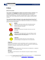
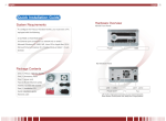
Enhance Technology IS316JS User Manual September 2011 (v1.0) 1 Enhance Technology, Inc. | 12221 Florence Ave. Santa Fe Springs, CA. 90670 | Tel: 562-777-3488 | Fax: 562-777-3499 | www.enhance-tech.com | [email protected] Preface About this manual This manual provides information regarding the hardware features, installation and configuration of the IS316JS. Information contained in the manual has been reviewed for accuracy, but not for product warranty because of the various environment/OS/settings. Information and specifications will be changed without further notice. Some pictures and screenshots might be different with the actual machine. This manual uses section numbering for every topic being discussed for easy and convenient way of finding information in accordance with the user’s needs. The following icons are being used for some details and information to be considered in going through with this manual: NOTES: These are notes that contain useful information and tips that the user must give attention to in going through with the subsystem operation. IMPORTANT! These are the important information that the user must remember. WARNING! These are the warnings that the user must follow to avoid unnecessary errors and bodily injury during hardware and software operation of the subsystem. CAUTION: These are the cautions that user must be aware of to prevent damage to the equipment and its components. Copyright No part of this publication may be reproduced, stored in a retrieval system, or transmitted in any form or by any means, electronic, mechanical, photocopying, recording or otherwise, without the prior written consent. Trademarks All products and trade names used in this document are trademarks or registered trademarks of their respective owners. Changes The material in this document is for information only and is subject to change without notice. 2 Enhance Technology, Inc. | 12221 Florence Ave. Santa Fe Springs, CA. 90670 | Tel: 562-777-3488 | Fax: 562-777-3499 | www.enhance-tech.com | [email protected] Limited Warranty Enhance Technology guarantees all components of Enhance Technology IS products are thoroughly tested before they leave the factory and should function normally under general usage. In case of any system malfunctions, Enhance Technology Corporation and its local representatives and dealers are responsible for repair without cost to the customer if the product fails within the warranty period and under normal usage. Enhance Technology Corporation is not responsible for any damage or loss of data deemed to be caused by its products. It is highly recommended that users conduct necessary back-up practices. FCC Compliance Statement This equipment has been tested and found to comply with the limits for a Class B digital device, pursuant to Part 15 of the FCC rules. These limits are designed to provide reasonable protection against harmful interference in residential installations. This equipment generates, uses, and can radiate radio frequency energy, and if not installed and used in accordance with the instructions, may cause harmful interference to radio communications. However, there is no guarantee that interference will not occur in a particular installation. If this equipment does cause interference to radio or television equipment reception, which can be determined by turning the equipment off and on, the user is encouraged to try to correct the interference by one or more of the following measures: 1. Reorient or relocate the receiving antenna 2. Move the equipment away from the receiver 3. Plug the equipment into an outlet on a circuit different from that to which the receiver is powered. 4. Consult the dealer or an experienced radio/television technician for help All external connections should be made using shielded cables 3 Enhance Technology, Inc. | 12221 Florence Ave. Santa Fe Springs, CA. 90670 | Tel: 562-777-3488 | Fax: 562-777-3499 | www.enhance-tech.com | [email protected] Before You Begin Before going through with this manual, you should read and focus on the following safety guidelines. Information about the IS316JS system’s packaging and delivery are also included. To provide reasonable protection against any harm on the part of the user and to obtain maximum performance, user is advised to be aware of the following safety guidelines particularly in handling hardware components: Upon receiving of the product: Place the product in its proper location. To avoid unnecessary dropping out, make sure that somebody is around for immediate assistance. It should be handled with care to avoid dropping that may cause damage to the product. Always use the correct lifting procedures. Upon installing of the product: Ambient temperature is very important for the installation site. It must not exceed 30°C. Due to seasonal climate changes; regulate the installation site temperature making it not to exceed the allowed ambient temperature. Before plugging-in any power cords, cables and connectors, make sure that the power switches are turned off. Disconnect first any power connection if the power supply module is being removed from the enclosure. Outlets must be accessible to the equipment. All external connections should be made using shielded cables and as much as possible should not be performed by bare hand. Using anti-static hand gloves is recommended. In installing each component, secure all the mounting screws and locks. Make sure that all screws are fully tightened. Follow correctly all the listed procedures in this manual for reliable performance. Packaging, Shipment and Delivery Before removing the subsystem from the shipping carton, you should visually inspect the physical condition of the shipping carton. Unpack and verify that the contents of the shipping carton are complete and in good condition. Exterior damage to the shipping carton may indicate that the contents of the carton are damaged. If any damage is found, do not remove the components; contact the dealer where you purchased the subsystem for further instructions. 4 Enhance Technology, Inc. | 12221 Florence Ave. Santa Fe Springs, CA. 90670 | Tel: 562-777-3488 | Fax: 562-777-3499 | www.enhance-tech.com | [email protected] Table of Contents Preface.................................................................................................................2 Limited Warranty.................................................................................................3 FCC Compliance Statement ...............................................................................3 Before You Begin................................................................................................4 Chapter 1 Introduction .....................................................................................6 Overview ...........................................................................................................6 Packaging, Shipment and Delivery....................................................................6 Package Contents .............................................................................................6 Front View .........................................................................................................7 Disk Tray & HDD Statues Indicator ...................................................................7 LCD Controller Panel ........................................................................................8 LCD Controller Panel Diagram ..........................................................................9 Rear View........................................................................................................10 Chapter 2 Hardware Installation ....................................................................11 Overview .........................................................................................................11 Installing Hard Disk in a Tray...........................................................................11 Chapter 3 Firmware Upgrade .........................................................................13 5 Enhance Technology, Inc. | 12221 Florence Ave. Santa Fe Springs, CA. 90670 | Tel: 562-777-3488 | Fax: 562-777-3499 | www.enhance-tech.com | [email protected] Chapter 1 Introduction Overview Thank you for choosing the IS316JS 6G SAS JBOD storage. The IS316 JS is a 19inch 3U 16 bays rackmount JBOD storage array. A ground breaking direct attached storage array that combines a dual port, high-speed 6Gb/s SAS interface, professional grade redundant & hot-swappable components with a 12Gb/s storage expansion bus allowing the addition of multiple IS316JS arrays with absolutely no degradation in performance. Packaging, Shipment and Delivery Before removing the subsystem from the shipping carton, you should visually inspect the physical condition of the shipping carton. Unpack the subsystem and verify that the contents of the shipping carton are all there and in good condition. Exterior damage to the shipping carton may indicate that the contents of the carton are damaged. If any damage is found, do not remove the components; contact the dealer where you purchased the subsystem for further instructions. Package Contents The IS316JS storage should have following items included IS316JS System Unit x1 Installation User Guide (CD) x1 Power cords x2 RS232 null modem cable (phone jack to DB9) x1 Spare screws 6 Enhance Technology, Inc. | 12221 Florence Ave. Santa Fe Springs, CA. 90670 | Tel: 562-777-3488 | Fax: 562-777-3499 | www.enhance-tech.com | [email protected] Front View IS316JS NS2120 Hard Drive Slot Number Reference Chart Slot #4 Slot #3 Slot #2 Slot #1 Slot #8 Slot #7 Slot #6 Slot #5 Slot #12 Slot #11 Slot #10 Slot #9 Slot #16 Slot #15 Slot #14 Slot #13 Disk Tray & HDD Statues Indicator Activity LED Power/Fault LED Descripti Item HDD Activity LED This LED will blink blue when the hard drive is being accessed. HDD Power/Fault LED Green LED indicates power is on and hard drive status is good for this slot. If hard drive is defective or failed, the LED is Red. LED is off when there is no hard drive. 7 Enhance Technology, Inc. | 12221 Florence Ave. Santa Fe Springs, CA. 90670 | Tel: 562-777-3488 | Fax: 562-777-3499 | www.enhance-tech.com | [email protected] LCD Controller Panel The LCD front panel is an option to setup some system settings. To start using the LCD panel, press the Select button to login and configure the system. See the LCD menu diagram in the next section. Item Exit button Description EXIT Press this button to return to the previous menu. Select button This is used to enter the option you have selected. Up and Down Arrow buttons Use the Up or Down arrow keys to go through the information on the LCD screen. This is also used to move between each menu when you configure the system. POWER LED Green LED indicates system power is on Power Fail LED LED will turn to red and alarm will sound when the power supply is failed Fan Fail LED Temperature Voltage Warning LED Access LED LED will turn to red and alarm will sound when the fan is failed LED will turn to red and alarm will sound when system temperature irregularities LED will turn to red and alarm will sound when system voltage irregularities LED will blink blue when system is busy / active 8 Enhance Technology, Inc. | 12221 Florence Ave. Santa Fe Springs, CA. 90670 | Tel: 562-777-3488 | Fax: 562-777-3499 | www.enhance-tech.com | [email protected] LCD Controller Panel Diagram Model-Name Chassis ID:0 F/W V 1.1.7J Disk Status ID:001-16 > S 1*0* 33C S 2*0* 32C : S 15*0* 31C S 16*0* 30C Power Status Good > PSU-A: Good PSU-B: Good FAN Status Good > MF/PSU-A: 3409 RPM SF/PSU-A: 2616 RPM Voltage Status Good > Buzzer Status Disabled > Disk Value Start > SPINUP Interval 1 Second(s) > Port Definition Zone Status MF/PSU-B: 3479 RPM SF/PSU-B: 2596 RPM +5V : 5.23V +12V : 12.33V Disable Buzzer / Enable Buzzer 0 /1 Seconds Interval 1 : 16 9 Enhance Technology, Inc. | 12221 Florence Ave. Santa Fe Springs, CA. 90670 | Tel: 562-777-3488 | Fax: 562-777-3499 | www.enhance-tech.com | [email protected] Rear View Description Item 1. Power Switch Power on/off switch 2. Power Status LED Indicates power on or fail 3. Power Supply Unit A Hot-swappable redundant power supply unit A 4. Power Supply Unit B Hot-swappable redundant power supply unit B 5. Access LED When port is having access, the LED indicates blue 6. Link LED When port is connected, the LED indicate green 7. SAS IN Port A SAS connection A for host 8. SAS IN Port B SAS connection B for host 9. SAS OUT Port A SAS expansion port A 10.SAS OUT Port B SAS expansion port B 11.RS232 Port Use for upgrading the Firmware of JBOD controller. 12.Chassis ID Dial Use for assigning the chassis ID number. 13.Mute Use for silence the alarm beeper 14.HDD LED Indicates hard drive and system activity in blue 15.Fault LED Indicates system failure in red 16.Ready LED Indicates system is ready or powered on in green 17.System Fan System cooling fan 10 Enhance Technology, Inc. | 12221 Florence Ave. Santa Fe Springs, CA. 90670 | Tel: 562-777-3488 | Fax: 562-777-3499 | www.enhance-tech.com | [email protected] Chapter 2 Hardware Installation Overview Installing your IS316JS storage is simple and easy. To help you get started, the following chapter will help you quickly get your IS316JS storage up and running. Please read it carefully to prevent damaging your unit during installation. Before you begin, please be sure to read and understand the safety guidelines in the beginning of the manual. If possible, wear an anti-static wrist strap during installation to prevent static discharge from damaging the sensitive electronic components on the IS316JS storage. Be careful not to use magnetized screwdrivers around the IS316JS storage’s electronic components. Installing Hard Disk in a Tray (If your IS316JS storage comes with the hard disk, you can skip this section) Installing 3.5” Hard Disk 1) Press the tray open button to pull out a disk tray Tray Open Button 2) Pull the lever handle outwards to remove the tray from the enclosure to pull out the disk tray from the system. 3) Place the hard drive in the disk tray. 4) Install the mounting screws in Tray Hole A on the bottom to secure the drive in the disk tray. Tray Hole A 11 Enhance Technology, Inc. | 12221 Florence Ave. Santa Fe Springs, CA. 90670 | Tel: 562-777-3488 | Fax: 562-777-3499 | www.enhance-tech.com | [email protected] 5) Slide the tray into a slot. 6) Close the lever handle until you hear the latch click into place. Installing 2.5” Hard Disk 1) Press the tray open button to pull out a disk tray Tray Open Button 2) Pull the lever handle outwards to remove the tray from the enclosure to pull out the disk tray from the system. 3) Place the 2.5” hard drive in the disk tray. 7) Install the mounting screws in Tray Hole W on the bottom to secure the drive in the disk tray. Tray Hole W 4) Slide the tray into a slot. 5) Close the lever handle until you hear the latch click into place. 12 Enhance Technology, Inc. | 12221 Florence Ave. Santa Fe Springs, CA. 90670 | Tel: 562-777-3488 | Fax: 562-777-3499 | www.enhance-tech.com | [email protected] Chapter 3 Firmware Upgrade IMPORTANT: Before upgrade the JBOD firmware, please shut down server first or make sure no array setting on the JBOD disks. The new Firmware will effective after JBOD power cycle. 1. Used RS-232 Port (Phone jack to DB9) link IS316JS SAS JBOD, in command line please type “system upgrade”, than press “Enter”. 2. Select Transfer & Send File with in 25 seconds 13 Enhance Technology, Inc. | 12221 Florence Ave. Santa Fe Springs, CA. 90670 | Tel: 562-777-3488 | Fax: 562-777-3499 | www.enhance-tech.com | [email protected] 3. Select your firmware file path, and select Xmodem in the communication protocol, and click transfer button. 4. Wait for the transfer of file to complete. 14 Enhance Technology, Inc. | 12221 Florence Ave. Santa Fe Springs, CA. 90670 | Tel: 562-777-3488 | Fax: 562-777-3499 | www.enhance-tech.com | [email protected] 5. When the transfer and firmware update is complete, please power cycle the system. 6. In command line, type “system info”, you can see the Expander firmware version. 15 Enhance Technology, Inc. | 12221 Florence Ave. Santa Fe Springs, CA. 90670 | Tel: 562-777-3488 | Fax: 562-777-3499 | www.enhance-tech.com | [email protected]