1
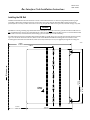
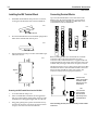
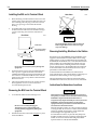
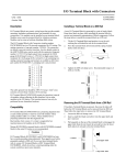
This Datasheet for the
IC670GBI102
115VAC/125VDC Bus Interface Unit
http://www.cimtecautomation.com/parts/p-14509-ic670gbi102.aspx
Provides the wiring diagrams and installation guidelines for this GE Field Control
module.
For further information, please contact Cimtec Technical Support at
1-866-599-6507
[email protected]
March 2010
GFK-0865G
Bus Interface Unit Installation Instructions
Installing the DIN Rail
The BIU Terminal Block must be mounted on a 7.5mm x 35mm DIN rail that has a conductive (unpainted) finish for proper
grounding. When using multiple rail sections, be sure they are properly aligned. Mount the DIN rail at least 4.25 inches
(10.80 cm) from a wireway or other obstruction on the wiring side of the BIU. Allow more space if I/O module wiring is very stiff.
Caution
This BIU has a metal grounding strip underneath the terminal block. It must be used with a grounded conductive DIN rail. It is
not compatible with A versions of I/O Terminal Blocks, which do not have a metal grounding strip. Do not use this BIU terminal
block with A version I/O terminal blocks; the resulting system would have poor noise immunity.
For added vibration resistance, the DIN rail should be installed on a panel using screws spaced approximately 6 inches (5.24cm)
apart. For maximum vibration resistance, drill two holes for the BIU Terminal Block mounting ears as shown below. After
mounting the terminal block on the DIN rail, install 3/8-inch (9.525mm) #6 screws (not supplied) through the mounting ears.
46458
4.25 in
4.50 in
11.43 cm
Wireway
5.90 in
14.99 cm
1.75 in
4.445 cm
5.00 in
12.70 cm
Clamp
Screw
4.31 in
10.95 cm
382
Installation Instructions
GFK-0865G
Installing the BIU Terminal Block
1.
Connecting Terminal Blocks
Tilt the BIU Terminal Block and position it over the rail,
catching the rail behind the tabs in the terminal block.
Up to four I/O Terminal Blocks can be connected to a Bus
Interface Unit. All I/O Terminal Blocks in a group must be
connected either before or after BIU. The BIU must not be
connected between I/O Terminal Blocks.
46384
46405
BIU
tabs
2.
DIN rail
Pivot the terminal block downward until the spring-loaded
latches in the terminal block click into place.
BIU
BIU
46385
3.
Tighten the DIN rail clamp screw. Recommended torque
is 4 in/lbs to 6 in/lbs.
46386
Tighten
BIU
Before installing the BIU on its terminal block, install the
connection cable to the next terminal block. A short
connection cable, as illustrated below, is supplied with each
I/OTerminal Block. Optional 21 inch (0.53 meter) cable is also
available. Only one longer cable can be used per I/O station.
The illustration below shows cable connection between a BIU
terminal block and an I/O Terminal Block. Make connections
between I/O Terminal Blocks in the same manner. The
connectors are keyed to assure proper installation.
46414
Connect here
when placing Bus
Interface Unit at
bottom of I/O Terminal Block
OR
Removing the BIU Terminal Block from the DIN Rail
1.
Loosen the DIN rail clamp screw.
2.
Insert a small flat-blade screwdriver into the upper latch
and pry it outward. Then, pull up gently on the top of the
terminal block to disengage the upper latch from the rail.
3.
Keep gently pulling the top of the terminal block away
from the rail. Insert the screwdriver into the lower latch
and pry it outward to free the terminal block.
a
a
Connect here
when placing
Bus Interface
Unit at top of I/O
Terminal Block
After installing the cable, be sure it is firmly seated on both
connectors.
Installation Instructions
383
GFK-0865G
Wiring the BIU Terminal Block
1.
drain wire with spaghetti tubing to prevent the Shield In and
Shield Out wires from touching each other, or the signal wires.
Connect an appropriate power source as shown below.
Low Voltage
Connections
(IC670GBI002)
High Voltage
Connections
(IC670GBII02)
–
24 VDC
+
BIU version IC670GBI102 provides internal overvoltage
protection. Terminal 4 is normally connected to frame
ground (terminal 3) by a factory-installed jumper. If
overvoltage protection is not required or is supplied
upstream this feature can be disabled by removing the
jumper, leaving pin 4 unconnected.
3.
Serial 1
Serial 2
Shield In
Shield Out
Main Bus
Connections
Shield Out
Shield In
Serial 2
Serial 1
B1
B2
Bin
Bout
Aout
Ain
A2
A1
115VAC or
125VDC
For BIU version IC670GBI102, if a DC supply is used the
polarity is not important.
2.
Redundant Bus
Connections
(optional)
Use one AWG #14 (2.1mm2) or two AWG #16 (1.3mm2)
\wiresperterminal. The wires into a terminal should be
the same type and size. Wires must be copper
conductors rated for 75 degrees C (167 degrees F) only.
Suggested torque for the terminal screws is 9 in/lbs.
Connect the ground terminal to the conductive mounting
panel with a 4-inch maximum length of AWG #14 (avg
2.1mm2) or larger wire. Use hardware such as star washers
to ensure ground integrity.
Noise Immunity
If the installation might exceed the surge immunity specified
in the Bus Interface Unit User’s Manual, it is prudent to provide
local transient protection as described in that manual.
System Grounding
All components of a control system and the devices it
controls must be properly grounded. Each Terminal Block
should be grounded in the manner described above. Control
panels and enclosures should be bonded to the plant system
ground per code.
Connect Serial 1 to the Serial 1 terminals of the previous
device and the next device.
2.
Connect Serial 2 to the Serial 2 terminals of the previous
device and the next device.
3.
Connect Shield In to Shield Out of the preceding device.
Connect Shield Out to Shield In of the next device. If the
BIU is the first device on a bus, Shield In can be left
unconnected. If it is the last device on a bus, Shield Out
can be left unconnected.
46387
Terminating
Resistor
Start
of Bus
Shield Out
Shield In
Serial 2
Serial 1
End
of Bus
Terminating
Resistor
Shield Out
Shield In
Serial 2
Serial 1
If the BIU is at either end of the bus (electrically), connect a 75,
100, 120, or 150– ohm terminating resistor across the Serial 1 and
Serial 2 terminals for that bus. The I/O System User’s Manual lists
the correct impedance to use for different types of bus cable.
Note: If the BIU will be powered up when not connected to
a properly terminated bus, connect a 75–ohm resistor across
its Serial 1 and Serial 2 terminals to assure proper powerup.
For applications using 150 ohm cables, prefabricated cables
are available in 15” (IC660BLC001) and 36” (IC660BLC003)
lengths. These cables terminate in mating connectors that
simplify wiring between I/O blocks. The 36” cable is
recommended for Terminal Block installations.
SER 2
SER 1
SHD IN
SHD OUT
Ground conductors should be connected in a tree fashion with
all branches routed to a central earth ground point. This ensures
that no ground conductor carries current from any other branch.
1.
Inadequate grounding may compromise system integrity in the
presence of power switching transients and surges.
Connecting the Communications Bus
If the BIU will be installed on a conventional single bus, make
the Bus A connections only. If the BIU will be installed on a
redundant (dual) bus, also connect Bus B. Do not attach an
external Bus Switching Module to a BIU.
For bus connections, the maximum exposed length of
unshielded wires should be 2 inches (5cm). Insulate each shield
SHD SHD SER SER
OUT IN
2
1
Prefabricated molded connectors with terminatingresistors
are available for 75 ohms (catalog number IC660BLM508) and
150 ohms (IC660BLM506). They can be used with
conventional bus cable and with the cables with pre-molded
connectors. Attach the prefabricated resistor to the female
cable end.
384
Installation Instructions
GFK-0865G
Side View
Installing the BIU on its Terminal Block
1.
Before installing a new Bus Interface Unit, remove the
cable slot plug on the end of the module that will cover
the connecting cable. The plug can be removed with
pliers, or by pressing out from inside the module
housing.
2.
To install the BIU on the terminal block, position the
module so that the cable slot in the module housing is
over the connecting cable. Press the module down
firmly.
End View
46426
46455
Caution
Cable Slot
b
Connecting Cable
(cross section)
Caution
Do not exert excessive force; it may damage the
equipment.
3.
4.
If unusual resistance is met, remove the Bus Interface
Unit. If power is applied, DO NOT TOUCH THE
CONNECTOR PINS! Inspect the Terminal Block, and
the connectors on the Terminal Block and on the Bus
Interface Unit. Remove any obstacles and reinsert the
Bus Interface Unit.
After placing the Bus Interface Unit onto the terminal
block, tighten its screws to secure it. Maximum
recommended torque is 9 in/lbs.
Removing the BIU from the Terminal Block
1.
Loosen the Bus Interface Unit retaining screws.
Caution
Be sure screws are fully disengaged.
Attempting to remove the module with
screw(s) partially engaged may damage the
equipment.
2.
Pull the Bus Interface Unit module straight away from
the Terminal Block.
Do not tilt the Bus Interface Unit to remove it.
Removing the Bus Interface Unit at an angle
may cause damage.
Removing/Installing Modules in the Station
Bus Interface Units IC670GBI002(F) and IC670GBI102A or later
support hot insertion/removal of I/O modules whose catalog
number suffix is J or above. Hot/insertion/removal requires I/O
Terminal Blocks IC670CHS101, 102, or 103. With these terminal
blocks, modules can be inserted/removed without removing
power to the I/O station or affecting other devices in the I/O
station. External power to the module itself must be removed
for hot insertion/removal. Hot insertion/removal can only be
performed in non-hazardous locations.
I/OTerminal Blocks IC670CHS001, 002, and 003 do not
support hot insertion/removal of modules. I/O Station power
should be off when installing or removing modules.
Mixing IC670CHS10x terminal blocks with IC670CHS00x
terminal blocks in the same I/O station is not recommended.
Instructions for Hazardous Locations
Warnings
This equipment is suitable for use in Class I, Division 2,
Groups A, B, C, and D or in non-hazardous locations only.
WARNING–Explosion Hazard–Substitution of
components may impair suitability for Class I, Division 2.
WARNING–Explosion Hazard–Do not disconnect
equipment unless power has been switched OFF or the
area is known to be non-hazardous.
When in hazardous locations, turn off power before replacing
or wiring modules. Do not remove or insert external modules
with power applied. Personal injury, system malfunction
and/or damage to the equipment may occur.
In non-hazardous locations, for personal safety field power
should be off while removing or inserting a high-voltage I/O
module. Avoid contact with module wiring and with the
exposed connectors on the I/O Terminal Block.