1
CAMERA CONTROL UNIT
INSTRUCTION MANUAL
IK-HD1E
For Customer Use
Enter below the Serial #
which is located on the
bottom of the cabinet. Retain
this information for future reference.
Model #
IK-HD1E
Serial #
FCC NOTICE
This equipment has been tested and found to comply with the limits for a Class A digital device, pursuant to Part 15 of the FCC Rules. These limits are designed to provide reasonable protection against
harmful interference when the equipment is operated in a commercial environment. This equipment
generates, uses, and can radiate radio frequency energy and, if not installed and used in accordance
with the instruction manual, may cause harmful interference to radio communications. Operation of this
equipment in a residential area is likely to cause harmful interference in which case the user will be
required to correct the interference at his own expense.
USER-INSTALLER CAUTION: Your authority to operate this FCC verified equipment could be voided if
you make changes or modifications not expressly approved by the party responsible for compliance to
Part 15 of the FCC Rules.
This Class A digital apparatus complies with Canadian ICES-003.
Cet appareil numérique de la classe A est comforme à la norme NMB-003 du Canada.
Following information is only for EU-member states:
The use of the symbol indicates that this product may not be treated as household waste.
By ensuring this product is disposed of correctly, you will help prevent potential negative
consequences for the environment and human health, which could otherwise be caused by
inappropriate waste handling of this product. For more detailed information about the takeback and recycling of this product, please contact your supplier where you purchased the
product or consult.
This manual is made from 100% recycled paper.
IK-HD1E_EN.indd 1
2007/11/20 9:33:12
SAFETY PRECAUTIONS
Safety icons
This manual contains safety instructions that must be observed in order to avoid potential
hazards that could result in personal injuries, damage to your equipment, or loss of data.
These safety cautions have been classified according to the seriousness of the risk, and the
icons highlight these instructions as follows:
Indicates a potentially hazardous situation which, if not avoided, could
result in death or serious injury.
Indicates a potentially hazardous situation which, if not avoided, may
result in minor or moderate injury.
Indicates a potentially hazardous situation which, if not avoided, may
result in property damage.
Stop operation immediately if any abnormality or defect occurs.
Use during an abnormal condition; such as emitting smoke, burning odors, damage
from dropping, invasion of foreign objects, etc. may result in fire and/or electrical
shock. Immediately disconnect the power source and contact your dealer.
Avoid installing in a shower room or a bathroom.
This may result in fire and/or electrical shock.
Do not operate in places where the product may get wet.
This may result in fire and/or electrical shock.
Do not repair, disassemble and/or modify by yourself.
This may result in fire and/or electrical shock. Always be sure to contact your
dealer for internal repair, check and cleaning of the product.
Use the specified power supply.
Otherwise, fire or electrical shock may occur.
Do not place anything on top of the unit.
Foreign materials, such as metals or liquids, getting into the product may result
in fire and/or electrical shock.
Do not put the product on an unstable, slanted or vibrating surface.
The product dropping or falling may result in serious injury.
Do not touch the product or any connection cables during a thunderstorm.
This may result in electrical shock.
2
IK-HD1E_EN.indd 2
2007/11/20 9:33:12
Note the following instructions when installing.
• Do not cover the product with any material.
• Do not place the product on any inflammable material such as a carpet or
blanket.
• Do not place the product in a confined space, as this may cause heat to
build up inside the product.
Failure to follow the above cautions may result in fire.
Do not place the product in direct sunshine and/or high temperature.
Temperature build up inside the product may result in fire.
Avoid placing in humid, smoky, or dusty places.
This may result in fire and/or electrical shock.
Ask your dealer to perform a periodical check and internal cleaning (approx.
once every five years).
Dust inside the product may result in fire. For check and cleaning cost, please
consult your dealer.
The following description is for that a camera head “IK-HD1H” connected to this camera control unit.
Do not point the lens directly at the sun and/or intensive light such as direct sunlight, etc.
Focusing of the light may result in eye injury and/or fire.
Disclaimer
We disclaim any responsibility and shall be held harmless for any damages or losses incurred by the
user in any of the following cases:
1. Fire, earthquake or any other act of God; acts by third parties; misuse by the user, whether intentional or accidental; use under extreme operating conditions.
2. Malfunction or non-function resulting in indirect, additional or consequential damages, including
but not limited to loss of expected income and suspension of business activities.
3. Incorrect use not in compliance with instructions in this instruction manual.
4. Malfunctions resulting from misconnection to other equipment.
5. Repairs or modifications made by the user or caused to be made by the user and carried out by
an unauthorized third party.
6. Notwithstanding the foregoing, Toshiba’s liabilities shall not, in any circumstances, exceed the
purchase price of the product.
Copyright and Right of Portrait
There may be a conflict with the Copyright Law and other laws when a customer uses, displays,
distributes, or exhibits an image picked up by the camera without permission from the copyright
holder. Please also note that transfer of an image or file covered by copyright is restricted to use
within the scope permitted by the Copyright Law.
Protection of Personal Information
Images taken by the camera that reveal the likeness of an individual person may be considered
personal information. To disclose, exhibit or transmit those images over the internet or otherwise,
consent of the person may be required.
3
IK-HD1E_EN.indd 3
2007/11/20 9:33:13
Limitation of Usage
The product is not designed for any “critical applications.” “Critical applications” means life support
systems, exhaust or smoke extraction applications, medical applications, commercial aviation, mass
transit applications, military applications, homeland security applications, nuclear facilities or systems
or any other applications where product failure could lead to injury to persons or less of life or
catastrophic property damage. Accordingly, [Toshiba/TAIS] disclaims any and all liability arising out of
the use of the product in any critical applications.
TABLE OF CONTENTS
1
2
CAUTIONS ON USE AND INSTALLATION ............................................ 6
COMPONENTS ....................................................................................... 6
3
4
ITEMS CONTROLLED BY THE ON SCREEN DISPLAY ........................ 7
NAMES AND FUNCTIONS...................................................................... 8
5
CONNECTION........................................................................................ 9
5.1 Standard Connection ..................................................................................................
5.2 Cautions on Connection..............................................................................................
5.3 Connection on Back Panel..........................................................................................
5.3A Connector Pin Assignments .....................................................................................
6
OPERATION........................................................................................... 11
6.1 Automatic Black Balance ............................................................................................
6.2 White Balance.............................................................................................................
6.3 Scene File ...................................................................................................................
6.4 Gain.............................................................................................................................
6.5 Shading Correction .....................................................................................................
7
9
10
10
10
11
12
14
14
15
MODE SETTING BY THE ON SCREEN DISPLAY ................................ 16
7.1 Using the Menus .........................................................................................................
7.2 Menus .........................................................................................................................
(1) SHUTTER (Electronic shutter) ....................................................................................
(1.1) Changing the setting in AUTO mode...................................................................
(1.2) Changing the setting in MANUAL mode ..............................................................
(1.3) Changing the setting in SS (Synchro. Scan) mode .............................................
(2) GAIN (Video gain) .......................................................................................................
(2.1) Changing maximum gain in AUTO (Automatic gain control) mode ....................
(2.2) Changing gain in MANUAL mode........................................................................
(3) WHT BAL (White Balance) ..........................................................................................
(3.1) Changing the setting in AWB (Automatic White Balance) mode ........................
(3.2) Changing the setting in ATW (Automatic Tracking White balance) mode .........
(3.3) Changing gain in MANUAL mode .......................................................................
(4) PROCESS ...................................................................................................................
(4.1) Changing gamma correction ON/OFF ................................................................
(4.2) Changing gamma correction level.......................................................................
(4.3) Changing detail (outline) gain..............................................................................
(4.4) Changing master pedestal ..................................................................................
(4.5) Changing DNR(Digital Noise Reduction).............................................................
(5) MATRIX(Matrix color correction) .................................................................................
(5.1) Changing Matrix color correction ON/OFF ..........................................................
(5.2) Changing MATRIX setting ...............................................................................
16
17
17
18
20
20
21
21
21
22
22
23
24
25
25
25
26
26
26
27
27
27
4
IK-HD1E_EN.indd 4
2007/11/20 9:33:13
(6) SYNC...........................................................................................................................
(6.1) INT screen...........................................................................................................
(6.2) Changing EXT. setting ........................................................................................
(7) OPTION.......................................................................................................................
(7.1) Changing OUTPUT mode ..................................................................................
(7.2) Changing shading correction mode ....................................................................
(7.3) Changing manual shading correction mode ........................................................
(7.4) Changing RGB SYNC .........................................................................................
(7.5) Changing RS232C baud rate ..............................................................................
(7.6) Changing OSD OUTPUT mode ..........................................................................
(8) Returning to factory settings .......................................................................................
7.3 External Sync ..............................................................................................................
(1) External sync signal input conditions...........................................................................
(2) External sync frequency range ....................................................................................
(3) Using the unit with external sync signal.......................................................................
(3.1) H (Horizontal) phase adjustment .........................................................................
7.4 Synchro. Scan Operation ............................................................................................
(1) Setting by 1H ...............................................................................................................
28
28
28
29
29
29
29
30
30
30
30
31
31
31
31
31
31
31
8
9
BEFORE MAKING A SERVICE CALL .................................................... 32
SPECIFICATIONS .................................................................................. 33
10
EXTERNAL APPEARANCE DIAGRAM................................................ 34
5
IK-HD1E_EN.indd 5
2007/11/20 9:33:13
1. CAUTIONS ON USE AND INSTALLATION
•
Handling the unit.
The following descriptions are for that a camera
head "IK-HD1H" connected to this camera control
unit.
Do not drop, jolt, or vibrate, as this may result in
damage to the unit. This may cause problems.
Treat the camera cables carefully to prevent
cable problems, such as breaks in the cable and
loose connections.
•
•
If there is an intense light at a location on the
screen such as a spot light, a blooming and smearing may occur. When intense light enters, vertical
stripes may appear on the screen. This is not a
malfunction. Ghosts may occur when there is an
intense light near the object. In this case, change
the shooting angle.
Install the camera in a location free from noise.
If the camera or the cables are located near power
utility lines or a TV, etc. undesirable noise may appear on the screen. In such a case, try to change
the location of the camera or the cable wiring.
•
Operating ambient temperature and humidity.
•
Moire
A moire pattern is an interference pattern
generated when two repetitive line patterns
overlap. This is not a malfunction. Eliminating the
repetitive line patterns, or aligning the two
patterns, will eliminate the moire.
•
Handling of the camera head and protection
cap.
Do not use the camera in places where temperature and humidity exceed the specifications. Picture quality will deteriolate and internal parts may
be damaged.
Be particularly careful when using in places exposed to direct sunlight. When shooting in hot
places, depending on the conditions of the object
and the camera (for example when the gain is increased), noise in the form of vertical strips or
white dots may occur. This is not a malfunction.
•
Keep the camera head and protection cap away
from as they may pose a choking hazard. The
protection cap protects the image sensing plane
when the lens is removed from the camera head,
do not discard.
When not using the camera for extended
periods of time.
•
Switch the control unit off and disconnect the
power supply.
•
Do not shoot intense light.
When cleaning the camera.
Unplug the power source before cleaning. Clean
with a soft dry cloth only. Do not use chemicals or
chemically treated cloths. Chemicals may damage
coatings and printed letters. When cleaning the
lens, use lens cleaning paper.
Avoid using or storing the camera in the following places:
Places filled with highly flammable gas.
•
Places near gasoline, benzene, or paint thinner.
Places subject to strong vibration.
Installation without a tripod.
Before installing the camera head, make sure
that the location can withstand the total weight of
the camera head.
Places containing chemicals (such as pesticides),
rubber or vinyl products for extended periods of
time.
If this is not the case, reinforce the area to
prevent the unit from dropping, which may result
in damage to the unit or personal injury.
2. COMPONENTS
1 Camera Control Unit ............................................................................................... 1
2 Accessories
a Instruction manual ........................................................................................ 1
6
IK-HD1E_EN.indd 6
2007/11/20 9:33:13
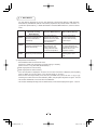
3
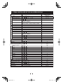
ITEMS CONTROLLED BY THE ON SCREEN DISPLAY
Item
Available selections
AUTO, MANUAL, SS
-100
0
100
00 10
05 05
10 00
1
10 20
PRESET A, PRESET B, PRESET C,
PRESET D, PRESET E
MANUAL speed
OFF, 1/100s, 1/125s, 1/250s, 1/500s, 1/1000s,
1/3000s, 1/5000s, 1/10000s, 1/30000s, 1/50000s
Syncro. scan
OFF, 1/1125H 560/1125H
MODE
AUTO, MANUAL, OFF
AUTO maximum gain
0dB to 18dB
MANUAL gain
0dB to 18dB
MODE
AWB, ATW, MANUAL
Color temperature
3200K, 5600K
-10
0
10
AWB R PAINT
-10
0
10
AWB B PAINT
AWB area
PRESET A, PRESET B, PRESET C,
PRESET D, PRESET E
-10
0
10
ATW R PAINT
-10
0
10
ATW B PAINT
-100
0
100
MANUAL R GAIN
-100
0
100
MANUAL B GAIN
Gamma correction
ON, OFF
Gamma correction level
-10
0
10
-7(OFF)
0
7
Detail gain
-100
0
100
Master pedestal
Digital noise reduction(DNR) ON, OFF
Correction ON/OFF
ON, OFF
-15
0
15
R hue
-15
0
15
R gain
-15
0
15
G hue
-15
0
15
G gain
-15
0
15
B hue
-15
0
15
B gain
-15
0
15
Ye hue
-15
0
15
Ye gain
-15
0
15
Cy hue
-15
0
15
Cy gain
-15
0
15
Mg hue
Mg gain
-15
0
15
0
650
Ext. Sync H phase adjustment -650
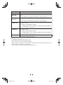
OUTPUT
Y/Pb /Pr , RGB
Shading correction mode
SET, MANUAL, OFF
Manual shading correction
-128
0
127
RGB SYNC
G, ALL ON, ALL OFF
RS232C baud rate
9600bps, 19200bps
OSD OUTPUT
ALL ON, Analog, Digital
Electronic shutter
MODE
AUTO level
AUTO peak/average
AUTO response speed
AUTO area
Preset value
(Factory setting)
MANUAL
0
05 05
10
PRESET A
OFF
Gain
White balance
OFF
OFF
18dB
0dB
AWB
3200K
0
0
PRESET A
Matrix color correction
0
0
0
0
ON
0
0
0
OFF
ON
0
0
0
0
0
0
0
0
0
0
0
0
0
Y/Pb /Pr
OFF
0
G
9600bps
ALL ON
7
IK-HD1E_EN.indd 7
2007/11/20 9:33:14
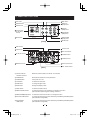
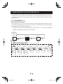
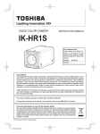
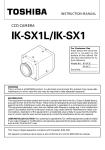
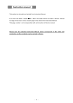
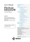
4. NAMES AND FUNCTIONS
FILE button
DISP button
POWER switch
MENU UP
(SHD) button
POWER LED
DATA UP
(AWB) button
Camera cable
for “IK-HD1H”
terminal
DATA DOWN
(ABB) button
GAIN button
MENU DOWN
(SHD) button
PAGE button
[Front]
PB/B terminal
PR/R terminal
Y/G terminal
KEY LOCK switch
DC IN 12V terminal
1
2
4
3
FORMAT switch
HD-SDI terminal
1 2 3 4 5
6 7 8 9
SYNC OUT terminal
REMOTE terminal
EXT. SYNC terminal
[Rear]
㽲 Camera cable for
“IK-HD1H” terminal
Where the camera cable for “IK-HD1H” is connected.
㽳 POWER LED
Illuminates to indicate the unit is powered on.
㽴 POWER switch
Turns power on or off.
㽵 FILE button
To switch the scene files.
㽶 GAIN button
To change the gain mode.
㽷 DISP button
Changes the display mode.
㽸 PAGE button
To switch and select menus.
㽹 MENU UP䋨SHD䋩button
To select the function to be confirmed or changed on the menu.
(Also used when performing auto shading correction.)
㽺 MENU DOWN(SHD) button To select and confirm the function or to change the menu.
㽻 DATA UP䋨AWB䋩button
To change the value of the function selected by the MENU (UP/DOWN) button.
(Also used when using AWB.)
㽼 DATA DOWN
䋨ABB䋩button
To change the value of the function selected by the MENU (UP/DOWN) button.
(Also used when using ABB.)
8
IK-HD1E_EN.indd 8
2007/11/20 9:33:14
㽽 DC IN 12V terminal
Accept a DC power input (12V).
㽾 Y/G terminal
Outputs Y or G. (BNC connector)
㽿 PB/B terminal
Outputs PB or B. (BNC connector)
㾀 PR/R terminal
Outputs PR or R. (BNC connector)
㾁 REMOTE terminal
To connect to a RS-232C device for remote control function.
㾂 EXT. SYNC terminal
Used when the camera output signal is synchronized to an external signal.
(BNC connector)
㾃 SYNC OUT terminal
Output terminal for synchronization signal. (BNC connector)
㾄 HD-SDI terminal
Video signal output terminal for HD-SDI format video signal. (BNC connector)
㾅 KEY LOCK switch
Enables/disables buttons 㽵 to 㽼.
FORMAT switch
5
Switches between 59.94i and 50i.
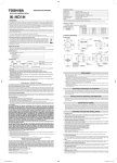
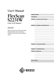
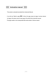
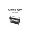
CONNECTION
5
1 Standard Connection
5. 1 -1 Analog Connection
Lens
(option)
Camera Cable
for IK-HD1E
䋨option䋩
IK-HD1E
Y/PB/PR
Camera
Control unit
IK-HD1H
䋨option䋩
Three Coaxial
Cables 75㱅
(option)
DC IN 12V
DC power supply
(option)
HD monitor
analog TV (option)
5. 1 -2 Digital Connection
Lens
(option)
Camera Cable
for IK-HD1E
䋨option䋩
IK-HD1E
HD-SDI
Camera
Control unit
IK-HD1H
䋨option䋩
One Coaxial
Cable 75㱅
(option)
DC IN 12V
DC power supply
(option)
HD monitor
digital TV (option)
* Please use a low conductor resistance cable for HD-SDI terminal.
9
IK-HD1E_EN.indd 9
2007/11/20 9:33:14
5
2 Caution on Connection
䊶 Only use optional camera head model # IK-HD1H with this camera controller.
The use of another head may cause damage to the control unit and camera head.
䊶 When connecting the camera cables, be sure to turn off the camera control unit and
any other equipment connected to it.
䊶 For DC power supply connecting to DC IN 12V terminal, use UL listed and/or CSA
approved ungrounded type AC adaptor with the specifications described below.
Power supply voltage
䋺 12V DC 㫧10%
Current rating
䋺 More than 1.5A
䋺 Less than 50mV (p-p)
Ripple voltage
䋺 HR10A-7P-4S by HIROSE electronics Co. Ltd
Connector
Pins 1, 2 䋺 12V
Pins 3, 4 䋺 GND
䊶 If the securing screw on the connector of the camera cable loosens, noise may appear
on the screen. Be sure to tighten the connector completely.
5
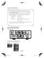
3 Connection on Back Panel
Back panel view
1
2
4
3
1 2 3 4 5
6 7 8 9
5
3A Connector Pin Assignments
DC IN 12V
REMOTE
1
2
3
4
1
2
3
4
5
6
7
8
9
+12V
+12V
GND
GND
NC
TXD
RXD
NC
GND
NC
NC
NC
NC
10
IK-HD1E_EN.indd 10
2007/11/20 9:33:14
6
OPERATION
A camera head "IK-HD1H" needs to be connected to this camera control unit from this section on.
㽲 Refer to the item “5. CONNECTION”, connect the equipment correctly.
㽳 Turn on the connected equipment and the camera.
㽴 When using the camera for the first time and when replacing the camera cable and the camera head, be
sure to perform the ABB adjustment, refer to the item “6.1 Automatic Black Balance”.
㽵 Aim the lens at the object, adjust the lens iris adjustment, focus adjustment, etc.
㽶 Refer to the item “6.2 White Balance”, make the adjustment.
㽷 Refer to the items “6.3 Scene File, 6.4 Gain, 7. MODE SETTING BY THE ON SCREEN DISPLAY”,
select the necessary items.
㽸 When switching the FORMAT switch on the back panel of the unit, be sure to perform the ABB adjustment,
refer to the item “6.1 Automatic Black Balance”.
6
1 Automatic Black Balance
Black balance adjustment is necessary to get the correct black picture level.
䊶 Close the lens iris.
䊶 If the color bar pattern is displayed on the screen or if the index menu/menu is displayed, press the
[DISP] button to disable the color bar pattern or the character display.
䊶 Hold the [DATA DOWN] button for approx. 1 second.
䊶 When the black balance adjustment operation starts, the character ABB blinks on the screen.
䊶 When the black balance adjustment operation finishes, the character ABB stops blinking and the result
appears for approx. 1 second.
Display
Meaning
ABB OK
Automatic black balance adjustment finished correctly.
ABB NG
Automatic black balance adjustment cannot be performed because the lens iris
CLOSE LENS
is open. Close the lens iris.
ABB NG
Automatic black balance adjustment cannot be performed.
Operate the automatic black balance again.
11
IK-HD1E_EN.indd 11
2007/11/20 9:33:15
6
2 White Balance
For white balance adjustment of this unit, ATW (Automatic Tracking White balance), AWB (Automatic
White Balance) and MANUAL (Manual white balance) adjustments are provided. Refer to the items “7.2
(3) WHT BAL (White Balance), 7. MODE SETTING BY THE ON SCREEN DISPLAY”, select the desired
mode.
Outline
Features
Notes
ATW
䋨 Automatic Tracking
White Balance䋩
䋩
The camera measures the
object color temperature and
adjusts the white balance
automatically.
AWB
䋨 Automatic White Balance䋩
䋩
Adjust white balance by
displaying the white object
inside the area set by AWB
menu and pressing the
[DATA UP] button.
MANUAL
䋨 Manual White Balance䋩
䋩
Adjust the white balance
manually using the WHT
BAL menu while shooting
the white object.
Measurement accuracy is
Tracks variations of color
temperature and adjusts white higher than ATW. This
mode is effective when
balance automatically.
shooting under less variations of color temperature.
Artificial white balance setting.
The manual adjustment is
most effective under shooting
conditions with no color
temperature variation.
If illumination is low, white
balance may not be corrected.
Adjustment is performed by
confirming with a vector
scope.
㽲 AWB(Automatic White Balance)
䊶 Set the MODE to AWB on the WHT BAL menu.
Perform the C.TEMP (color temperature conversion) setting, if necessary.
(Refer to the item “7.2 (3) WHT BAL (White Balance)”.)
3200K䋺Appropriate for indoor shooting.
5600K䋺Appropriate for outdoor shooting.
䊶 If the color bar pattern is displayed on the screen or if the index menu/menu is displayed, press the [DISP]
button to disable the color bar pattern or the character display on the menu.
䊶 Shoot a known white object entirely in the area set by the AWB menu (refer to the item “7.2 (3) (3.1) (d)
Confirming the contents of the zone area selected by AWB” ) and push [DATA UP] button for approx. 1 second.
䊶 The character AWB blinks on the screen when the AWB starts.
䊶 The character AWB stops blinking when the AWB finishes, and the result is displayed for approx. 1 second.
12
IK-HD1E_EN.indd 12
2007/11/20 9:33:15
Display
Meaning
AWB OK
Automatic white balance adjustment finished correctly.
AWB NG
Automatic white balance adjustment cannot be performed because the video level is
too low.
Adjust the video level by increasing the illumination or opening the lens iris.
LEVEL LOW
AWB NG
LEVEL HIGH
AWB NG
C. TEMP LOW
Automatic white balance adjustment cannot be performed because the video level is
too high.
Adjust the video level by decreasing the illumination or closing the lens iris.
Automatic white balance adjustment cannot be performed because the color
temperature is too low.
If the C.TEMP is set to 5600K, set to 3200K.
If the message appears with the C.TEMP set to 3200K, change the illumination or
use a color temperature conversion filter.
AWB NG
C. TEMP HIGH
Automatic white balance adjustment cannot be performed because the color
temperature is too high.
If the C.TEMP is set to 3200K, set to 5600K.
If the message appears with the C.TEMP set to 5600K, change the illumination or
use the color temperature conversion filter.
AWB NG
Automatic white balance adjustment cannot be performed for other reasons. Such as
no white area is included in an object, etc.
㽳 MANUAL(Manual white balance)
䊶 Set the MODE to MANUAL on the WHT BAL menu.
(Refer to the item “7.2 (3) WHT BAL (White Balance)”.)
䊶 Shoot a known white object, set the white balance by adjusting the levels of R GAIN and B GAIN on the
menu, confirming with a monitor or a vector scope.
(Refer to the item “7.2 (3) (3.3) Changing gain in MANUAL mode”.)
13
IK-HD1E_EN.indd 13
2007/11/20 9:33:15
6
3 Scene File
Five scene files (A, B, C, D, E) are available as user memories for this unit. These are chosen depending
on shooting conditions. By using the [FILE] button, the camera operation is changed immediately from the
currently selected Scene File to the next. (Refer to the item “7. MODE SETTING BY THE ON SCREEN
DISPLAY”.)
䊶 While any menu is displayed, pressing the [FILE] button will display the menu settings for the next Scene File:
FILE A 㸢 FILE B 㸢 FILE C 㸢 FILE D 㸢 FILE E
䊶 When the [FILE] button is pressed while the camera is in live image mode, the current scene file selection
at that time is displayed for approx. 3 seconds in the upper right corner of the screen. If the [FILE] button is
pressed again while the position is displayed, the scene file cycles as described above.
6
4 Gain
When the image is dark even if the lens iris is open, change the gain (video gain) to get the desired video level.
For gain adjustment of the unit, AUTO (Automatic gain control), MANUAL (Manual), OFF (0 dB) modes
are provided. Select the mode on the GAIN menu. (Refer to the item “7.2 (2) GAIN (Video gain)”.)
㽲 AUTO(Automatic gain control)
When the output is low, gain is automatically adjusted to a suitable video level.
The maximum value of gain is 18dB, and can be set from 0 to 18dB in 1dB steps. (Refer to the item
“7.2 (2) (2.1) Changing the maximum gain in AUTO (Automatic gain control) mode”.)
Video level (LEVEL), peak average value ratio (PEAK/AVE), and measurement light area (AREA) is linked
to the setting on the automatic shutter. (Refer to the item “7.2 (1) (1.1) Changing the setting in AUTO mode”.)
㽳 MANUAL(Manual gain)
Gain adjustment is performed on the GAIN menu. The adjustment range is from 0 to 18dB in 1dB steps.
(Refer to the item “7.2 (2) (2.2) Changing gain in MANUAL mode”.)
㽴 OFF
Gain is fixed at 0 dB.
Gain button
ԘIf the [GAIN] button is pressed, the current setting mode is on the GAIN menu for approx. 3 seconds.
GAIN menu : OFF → GAIN OFF
: AUTO → GAIN AUTO
: MANUAL㧖㧖dB → GAIN dB
“㧖㧖” shows the setting gain in MANUAL mode.
ԙIf the [GAIN] button is pressed again while the current setting mode is displayed, the gain mode can be
changed.
GAIN of MAX GAIN in AUTO mode and MANUAL mode can not be changed.
OFF 㸢 AUTO 㸢 MANUAL
14
IK-HD1E_EN.indd 14
2007/11/20 9:33:16
Note:
White, red, green, or blue dots may occur when the gain is increased. This is not a malfunction, just
certain characteristics of the CCD becoming more visible.
6
5 Shading Correction
Due to the lens used or the environmental condition, color shading may occur at the upper and lower edge
of the screen. If this happens, the shading correction function can be used to decrease the amount of color
shading. For shading correction of the unit, SET (Automatic shading correction), MANUAL (Manual shading
correction), and OFF (no shading correction) modes are provided. Select the mode on the OPTION menu.
(Refer to the item “7.2 (7) (7.2) Changing shading correction mode”.)
㽲 SET(Auto shading)
䍃 If the color bar pattern is displayed on the screen or if the index menu/menu is displayed, press the
[DISP] button to remove them from the screen.
䊶 Push the [MENU UP] button for approx. 1 second.
䊶 When the automatic shading correction operation starts, the character SHD blinks on the screen.
䊶 When the automatic shading correction operation terminates, the character SHD ends blinking and the
result is displayed for approx. 1 second.
Display
Meaning
SHD OK
Automatic shading correction operation finished correctly.
SHD OK
Automatic shading correction operation finished, however, the correction
LIMIT
necessary exceeds the camera’s range so the maximum possible value is applied.
SHD NG
Automatic shading correction cannot be performed because the video level is too
LEVEL LOW
low. Adjust the video level by increasing the illumination or opening the lens iris.
SHD NG
Automatic shading correction cannot be performed because the video level is too
LEVEL HIGH
high. Adjust the video level by decreasing the illumination or closing the lens iris.
㽳 MANUAL(Manual Shading)
Perform the correction amount setting on the OPTION menu, confirming with a monitor or a vector scope.
(Refer to the “7.2 (7) (7.3) Changing manual shading correction mode”.)
㽴 OFF
The status is no shading correction.
* Shading correction is only effective when the lens iris and zoom ratio is fixed. Use the unit with
.
SHADING OFF for variable lens conditions.
Note:
Before shading correction is performed, please shoot a known white object that fills the screen in
the proper video level and set the automatic white balance (AWB) .
15
IK-HD1E_EN.indd 15
2007/11/20 9:33:16
7
MODE SETTING BY THE ON SCREEN DISPLAY
Various settings can be controlled on the unit by using the on screen menu displayed on the monitor. The
contents once set are memorized in the scene files (A, B, C, D, E) selected, so if the power turns off, it is
unnecessary to set again when using the unit next time. When the setting is performed, select the menu of
the item to be set.
7
1 Using the Menus
When the power turns on, the normal screen showing only the video signal appears. Change the output to
each screen (video signal output, color bar screen, Index menu, menus, and area menu) by using the [DISP],
[PAGE], [MENU UP], and [MENU DOWN] buttons.
* A menu is selected when pushing the [PAGE] button after moving the “㸢” on the screen by the [MENU
UP], [MENU DOWN] button while the Index menu is displayed.
POWER SW
ON
Video signal output
Color bar screen
DISP
DISP
Index menu
DISP
DISP
PAGE
PAGE
PAGE
Menus
PAGE
1.SHUTTER
2.GAIN
PAGE
3.WHT BAL
4.PROCESS
PAGE
PAGE
AUTO
AUTO
AWB
GAMMA
ON
MANU
MANU
ATW
GAMMA
OFF
OFF
MANU
SS
5.MATRIX
PAGE
6.OPTION
6.SYNC
PAGE
PAGE
ON
INT
Y/Pb /Pr
OFF
EXT.
RGB
16
IK-HD1E_EN.indd 16
2007/11/20 9:33:16
7
2 Menus
䊶 Select the menu to change the setting by referring to the item “7.1 Using the Menus”.
䊶 When the [MENU UP], [MENU DOWN] buttons are pushed, the “㸢” on the screen moves up and down.
Move the “㸢” to the item whose setting you wish to change.
1
SHUTTER䋨
䋨Electronic shutter䋩
The electronic shutter has four modes; AUTO, MANUAL, SS(Synchro. Scan).
Press the “Page” button to enter the Shutter Page. Use the “Data Up/Down” buttons to select the Shutter
Mode.
AUTO
MANUAL
SS
AUTO
䋺 The exposure time is controlled automatically to obtain the video level set.
MANUAL
䋺 It is possible to select the exposure time from eleven speed settings; OFF (1/60s), 1/100s,
1/125s, 1/250s, 1/500s, 1/1000s, 1/3000s, 1/5000s, 1/10000s, 1/30000s, 1/50000s.
Note:
When setting a rapid shutter speed, sensitivity degrades according to the speed.
When a discharging light such as fluorescent lamp, etc. is used for the illumination,
SS
the flicker may be large.
䋺 Shutter speed can be set by the horizontal scanning time (1H) unit.
17
IK-HD1E_EN.indd 17
2007/11/20 9:33:16
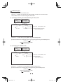
䋨 1䋮
䋮1䋩
䋩 Changing the setting in AUTO mode
Move up and down
by pushing
MENU UP,DOWN
Select the desired
value by pushing
DATA UP,DOWN
Shutter mode
AUTO, MANUAL, SS
Video level adjustment
--
1
SHUTTER --
-100 to 100
<FILE A>
Peak and average ratio adjustment
MODE
LEVEL
PEAK AVE
SPEED
AREA
AUTO
0
05 05
10
PRESET A
00
10 to 10
Automatic shutter response speed adjustment
00
1 to 20
Automatic shutter area selection
PRESET A, PRESET B, PRESET C, PRESET D, PRESET E
< MODE = AUTO>
(a) Changing the video level in the automatic shutter mode
㽲 Move the “㸢” to LEVEL by pushing [MENU UP], [MENU DOWN] buttons.
㽳 Select the video level by pushing [DATA UP], [DATA DOWN] buttons.
㸢 The value increases by pushing [DATA UP]
-100
0
100
㸠 The value decreases by pushing [DATA DOWN]
(b) Changing the automatic shutter detection (ratio between peak and average value)
㽲 Move the “㸢” to PEAK/AVE by pushing [MENU UP], [MENU DOWN] buttons.
㽳 Select the ratio between peak and average value by pushing [DATA UP], [DATA DOWN] buttons.
(Peak䋺Average)
00䋺10
㸢 The peak value increases by pushing [DATA UP]
05䋺05
10䋺00
㸠 The peak value decreases by pushing [DATA DOWN]
(c) Changing the automatic shutter response speed
㽲 Move the “㸢” to SPEED by pushing [MENU UP], [MENU DOWN] buttons.
㽳 Select the response speed by pushing [DATA UP], [DATA DOWN] buttons.
㸢 The response speed becomes faster by pushing [DATA UP]
1
10
20
㸠 The response speed becomes slower by pushing [DATA DOWN]
18
IK-HD1E_EN.indd 18
2007/11/20 9:33:17
(d) Changing the automatic shutter zone area
㽲 Move the “㸢” to AREA by pushing [MENU UP], [MENU DOWN] buttons.
㽳 Select the measurement light area by pushing [DATA UP], [DATA DOWN] buttons.
䌛DATA UP䌝
PRESET A
PRESET B
PRESET C
PRESET D
䌛DATA DOWN䌝
PRESET E
The available picture area is shown by the shading correction on the screen that is parted in 64.
PRESET A
PRESET B
PRESET C
PRESET D
PRESET E
Note:
These available picture areas are not displayed on the screen.
19
IK-HD1E_EN.indd 19
2007/11/20 9:33:17
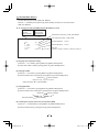
䋨 1䋮
䋮2䋩
䋩 Changing the setting in MANUAL mode
Move up and down
by pushing
MENU UP,DOWN
Select the desired
value by pushing
DATA UP,DOWN
Shutter mode
--
1
SHUTTER --
MODE
MANUAL
AUTO, MANUAL, SS
<FILE A>
Shutter speed setting
OFF, 1/100s, 1/125s, 1/250s, 1/500s, 1/1000s,
1/3000s, 1/5000s, 1/10000s, 1/30000s, 1/50000s
MANUAL
1 10000s
< MODE = MANUAL>
(a) Changing the shutter speed
㽲 Move the “㸢” to MANU by pushing [MENU UP], [MENU DOWN] buttons.
㽳 Select the shutter speed by pushing [DATA UP], [DATA DOWN] buttons.
OFF
1/100s
1/125s
䌛DATA UP䌝
1/500s 1/1000s
1/250s
1/3000s
1/5000s
1/10000s
1/30000s
1/50000s
䌛DATA DOWN䌝
䋨 1䋮
䋮3䋩
䋩 Changing the setting in SS (Synchro. Scan) mode
Move up and down
by pushing
MENU UP,DOWN
Select the desired
value by pushing
DATA UP,DOWN
Shutter mode
--
1
SHUTTER --
MODE
SYNCHRO SCAN
AUTO, MANUAL, SS
<FILE A>
Synchro. scan setting
1 1125H
560 1125H
SS
OFF
OFF
< MODE = SS >
(a) Changing the shutter speed setting
㽲 Move the “㸢” to SYNCHRO SCAN by pushing [MENU UP], [MENU DOWN] buttons.
㽳 Select the shutter speed by pushing [DATA UP], [DATA DOWN] buttons.
䌛DATA UP䌝
1/1125H
560/1125H
OFF
䌛DATA DOWN䌝
20
IK-HD1E_EN.indd 20
2007/11/20 9:33:17
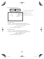
2
GAIN (Video gain)
GAIN has three modes; AUTO, MANUAL, OFF.
Move the “㸢 ” to MODE, push the [DATA UP], [DATA DOWN], and select one of the three modes :
AUTO, MANUAL, OFF. In the OFF mode, gain is fixed to 0dB.
䋨 2䋮
䋮1䋩
䋩 Changing maximum gain in AUTO (Automatic gain control) mode
Move up and down
by pushing
MENU UP,DOWN
--
2
GAIN
Select the desired
value by pushing
DATA UP,DOWN
--
<FILE A>
Gain mode
MODE
MAX GAIN
AUTO
10dB
AUTO, MANUAL, OFF
Automatic maximum gain setting
0dB to 18dB (1dB step)
㽲 Move the “㸢” to MAX GAIN by pushing [MENU UP], [MENU DOWN] buttons.
㽳 Select the desired value of automatic maximum gain by pushing [DATA UP], [DATA DOWN] buttons.
䌛DATA UP䌝
0dB
18dB
䌛DATA DOWN䌝
䋨 2䋮
䋮2䋩
䋩 Changing gain in MANUAL mode
Move up and down
by pushing
MENU UP,DOWN
--
2
GAIN
Select the desired
value by pushing
DATA UP,DOWN
--
<FILE A>
Gain mode
MODE
MANUAL
MANUAL
0dB
AUTO, MANUAL, OFF
Manual gain setting
0dB to 18dB (1dB step)
㽲 Move the “㸢” to MANUAL by pushing [MENU UP], [MENU DOWN] buttons.
㽳 Select the desired value of manual gain by pushing [DATA UP], [DATA DOWN] buttons.
䌛DATA UP䌝
0dB
18dB
䌛DATA DOWN䌝
21
IK-HD1E_EN.indd 21
2007/11/20 9:33:18
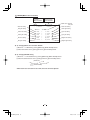
䋨3䋩
䋩 WHT BAL(White Balance)
The WHT BAL has three modes; AWB, ATW, MANUAL.
Move the “ 㸢” to MODE, push the [DATA UP], [DATA DOWN], and select one of the three modes :
AWB, ATW, MANUAL.
䋨 3䋮
䋮1䋩
䋩 Changing the setting in AWB(Automatic White Balance) mode
Move up and down
by pushing
MENU UP,DOWN
Select the desired
value by pushing
DATA UP,DOWN
White balance mode setting
Color temperature setting
--
3
WHT BAL --
MODE
C TEMP
R PAINT
B PAINT
AREA
AWB, ATW, MANUAL
3200K, 5600K
<FILE A>
AWB
3200K
0
0
PRESET A
R PAINT adjustment
-10 to 10
B PAINT adjustment
-10 to 10
AWB area
PRESET A, PRESET B, PRESET C, PRESET D, PRESET E
(a) Changing color temperature setting
㽲 Move the “㸢” to C.TEMP by pushing [MENU UP], [MENU DOWN] buttons.
㽳 Select either 3200K or 5600K by pushing [DATA UP], [DATA DOWN] buttons.
(b) Changing R PAINT
㽲 Move the “㸢” to R PAINT by pushing [MENU UP], [MENU DOWN] buttons.
㽳 Select the desired value of red paint by pushing [DATA UP], [DATA DOWN] buttons.
䌛DATA UP䌝
䋭10
Red is decreased.
Red is increased.
0
10
䌛DATA DOWN䌝
(c) Changing B PAINT
㽲 Move the “㸢” to B PAINT by pushing [MENU UP], [MENU DOWN] buttons.
㽳 Select the desired value of blue paint by pushing [DATA UP], [DATA DOWN] buttons.
䌛DATA UP䌝
䋭10
Blue is decreased.
Blue is increased.
0
10
䌛DATA DOWN䌝
(d) Confirming the contents of the zone area selected by AWB
㽲 Move the “㸢” to AREA DISP by pushing [MENU UP], [MENU DOWN] buttons.
㽳 Select the desired area by pushing [DATA UP], [DATA DOWN] buttons.
22
IK-HD1E_EN.indd 22
2007/11/20 9:33:18
The available picture area is shown by the shading correction on the screen that is parted in 64.
PRESET A
PRESET B
PRESET C
PRESET D
PRESET E
Note:
These available picture areas are not displayed on the screen.
䋨 3䋮
䋮2䋩
䋩 Changing the setting in ATW(Automatic Tracking White balance) mode
Move up and down
by pushing
MENU UP,DOWN
--
3
Select the desired
value by pushing
DATA UP,DOWN
WHT BAL --
MODE
R PAINT
B PAINT
White balance mode
AWB, ATW, MANUAL
R PAINT adjustment
-10 to 10
B PAINT adjustment
-10 to 10
<FILE A>
ATW
0
0
(a) Changing R PAINT
㽲 Move the “㸢” to R PAINT by pushing [MENU UP], [MENU DOWN] buttons.
㽳 Select the desired value of red paint by pushing [DATA UP], [DATA DOWN] buttons.
䌛DATA UP䌝
䋭10
Red is decreased.
Red is increased.
0
10
䌛DATA DOWN䌝
(b) Changing B PAINT
㽲 Move the “㸢” to B PAINT by pushing [MENU UP], [MENU DOWN] buttons.
㽳 Select the desired value of blue paint by pushing [DATA UP], [DATA DOWN] buttons.
䌛DATA UP䌝
䋭10
Blue is decreased.
Blue is increased.
0
10
䌛DATA DOWN䌝
23
IK-HD1E_EN.indd 23
2007/11/20 9:33:18
䋨 3䋮
䋮3䋩
䋩 Changing gain in MANUAL mode
Move up and down
by pushing
MENU UP,DOWN
--
3
Select the desired
value by pushing
DATA UP,DOWN
WHT BAL --
MODE
R GAIN
B GAIN
C TEMP
White balance mode
AWB, ATW, MANUAL
Red gain adjustment
-100 to 100
Blue gain adjustment
-100 to 100
<FILE A>
MANUAL
0
0
3200k
Color temperature setting
3200K, 5600K
(1) Changing the red gain
㽲 Move the “㸢” to R GAIN by pushing [MENU UP], [MENU DOWN] buttons.
㽳 Select the desired value of red gain by pushing [DATA UP], [DATA DOWN] buttons.
䌛DATA UP䌝
䋭10
Red is decreased.
Red is increased.
0
10
䌛DATA DOWN䌝
(2) Changing the blue gain
㽲 Move the “㸢” to B GAIN by pushing [MENU UP], [MENU DOWN] buttons.
㽳 Select the desired value of blue gain by pushing [DATA UP], [DATA DOWN] buttons.
䌛DATA UP䌝
䋭10
Blue is decreased.
Blue is increased.
0
10
䌛DATA DOWN䌝
24
IK-HD1E_EN.indd 24
2007/11/20 9:33:18
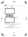
䋨4䋩
䋩 PROCESS
Move up and down
by pushing
MENU UP,DOWN
Select the desired
value by pushing
DATA UP,DOWN
Gamma correction
--
4
PROCESS --
GAMMA ON/OFF
GAMMA
DTL GAIN
M PED
DNR
ON, OFF
Gamma correction level setting
<FILE A>
Detail gain setting
ON
0
0
0
OFF
-10 to 10
-7 to 7
Master pedestal setting
Digital noise reduction
-100 to 100
ON,OFF
䋨 4䋮
䋮1䋩
䋩 Changing gamma correction ON/OFF
㽲 Move the “㸢” to GAMMA ON/OFF by pushing [MENU UP], [MENU DOWN] buttons.
㽳 Select either ON or OFF by pushing [DATA UP], [DATA DOWN] buttons.
Move up and down
by pushing
MENU UP,DOWN
--
4
Select the desired
value by pushing
DATA UP,DOWN
PROCESS --
GAMMA ON/OFF
DTL GAIN
M PED
DNR
<FILE A>
OFF
0
0
OFF
Gamma correction
ON, OFF
Detail gain setting
-7 to 7
Master pedestal setting
Digital noise reduction
-100 to 100
ON,OFF
Menu when GAMMA OFF is selected.
䋨 4䋮
䋮2䋩
䋩 Changing gamma correction level
㽲 Move the “㸢” to GAMMA by pushing [MENU UP], [MENU DOWN] buttons.
㽳 Select the desired value of gamma correction level by pushing [DATA UP], [DATA DOWN] buttons.
䌛DATA UP䌝
䋭10
Correction amount becomes smaller.
Correction amount becomes larger.
0
10
䌛DATA DOWN䌝
* When OFF is selected in GAMMA ON/OFF selection line, the gamma correction level change cannot
be changed.
25
IK-HD1E_EN.indd 25
2007/11/20 9:33:19
䋨 4䋮
䋮3䋩
䋩 Changing detail (outline) gain
㽲 Move the “㸢” to DTL GAIN by pushing [MENU UP], [MENU DOWN] buttons.
㽳 Select the desired value of the detail gain by pushing [DATA UP], [DATA DOWN] buttons.
䌛DATA UP䌝
䋭7
The detail decreases.
The detail increases.
0
7
䌛DATA DOWN䌝
䋨 4䋮
䋮4䋩
䋩 Changing master pedestal
㽲 Move the “㸢” to M. PED by pushing [MENU UP], [MENU DOWN] buttons.
㽳 Select the desired value of the master pedestal by pushing [DATA UP], [DATA DOWN] buttons.
䌛DATA UP䌝
䋭100
M PED decreases
M PED rises
0
100
䌛DATA DOWN䌝
䋨 4䋮
䋮5䋩
䋩 Changing DNR (Digital Noise Reduction)
㽲 Move the “㸢” to DNR by pushing [MENU UP], [MENU DOWN] buttons.
㽳 Select either ON or OFF by pushing [DATA UP], [DATA DOWN] buttons.
Note:
When DNR is set to ON, noise is reduced, an accidental image might be outstanding while shooting
moving objects.
26
IK-HD1E_EN.indd 26
2007/11/20 9:33:19
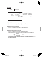
䋨5䋩
䋩 MATRIX(Matrix color correction)
Move up and down
by pushing
MENU UP,DOWN
Red hue setting
--
5
MATRIX --
Red gain setting
MATRIX
ON
Green hue setting
R
R
G
G
B
B
0
0
0
0
0
0
Green gain setting
Blue hue setting
Select the desired
value by pushing
DATA UP,DOWN
HUE
GAIN
HUE
GAIN
HUE
GAIN
<FILE A>
Matrix color correction
ON, OFF
Yellow hue setting
Yellow gain setting
Ye
Ye
Cy
Cy
Mg
Mg
HUE
GAIN
HUE
GAIN
HUE
GAIN
0
0
0
0
0
0
Blue gain setting
Cyan hue setting
Cyan gain setting
Magenta hue setting
Magenta gain setting
䋨 5䋮
䋮1䋩
䋩 Changing Matrix color correction ON/OFF
㽲 Move the “㸢” to MATRIX by pushing [MENU UP], [MENU DOWN] buttons.
㽳 Select either ON or OFF by pushing [DATA UP], [DATA DOWN] buttons.
䋨 5䋮
䋮2䋩
䋩 Changing MATRIX setting
㽲 Move the “㸢” to the desired item by pushing [MENU UP], [MENU DOWN] buttons.
㽳 Select the desired value of color by pushing [DATA UP], [DATA DOWN] buttons.
䌛DATA UP䌝
䋭15
0
15
䌛DATA DOWN䌝
* When matrix color correction is set to OFF, the color cannot be adjusted.
27
IK-HD1E_EN.indd 27
2007/11/20 9:33:19
䋨6䋩
䋩 SYNC
When an external sync signal is input, the display changes from INT (internal sync) to EXT.(external sync)
automatically.
INT
EXT
䋨 6䋮
䋮1䋩
䋩 INT screen
--
6
SYNC --
MODE
<FILE A>
INT
䋨 6䋮
䋮2䋩
䋩 Changing EXT. setting
Move up and down
by pushing
MENU UP,DOWN
Select the desired
value by pushing
DATA UP,DOWN
Sync system display
--
6
SYNC --
<FILE A>
H PHASE
MODE
H PHASE
-650 to 650
EXT
0
(a) Adjusting horizontal phase
㽲 Move the “㸢” to H PHASE by pushing [MENU UP], [MENU DOWN] buttons.
㽳 Select the desired value of horizontal phase by pushing [DATA UP], [DATA DOWN] buttons.
䌛DATA UP䌝
䋭650
0
650
䌛DATA DOWN䌝
* If the phase difference is big, press [DATA UP]/[DATA DOWN] button for a while.
It makes the setting shift by tens place.
28
IK-HD1E_EN.indd 28
2007/11/20 9:33:20
䋨7䋩
䋩 OPTION
Move up and down
by pushing
MENU UP,DOWN
Select the desired
value by pushing
DATA UP,DOWN
OUTPUT
--
7
OPTION
--
Y/Pb/Pr, RGB
<FILE A>
OUTPUT
Y/Pb/Pr
SHADING
BAUD RATE
OSD OUTPUT
OFF
9600bps
ALL ON
SHADING MODE
SET, MANUAL, OFF
RS232C baud rate
9600bps, 19200bps
OSD OUTPUT
ALL ON, Analog, Digital
䋨 7䋮
䋮1䋩
䋩 Changing OUTPUT mode
㽲 Move the “㸢” to OUTPUT by pushing [MENU UP], [MENU DOWN] buttons.
㽳 Select either Y/Pb/Pr or RGB by pushing [DATA UP], [DATA DOWN] buttons.
䋨 7䋮
䋮2䋩
䋩 Changing shading correction mode
㽲 Move the “㸢” to SHADING by pushing [MENU UP], [MENU DOWN] buttons.
㽳 Select SET, MANUAL or OFF by pushing [DATA UP], [DATA DOWN] buttons.
䋨 7䋮
䋮3䋩
䋩 Changing manual shading correction mode
㽲 Move the “㸢” to MANUAL by pushing [MENU UP], [MENU DOWN] buttons.
㽳 Select the desired value of manual shading correction by pushing [DATA UP], [DATA DOWN] buttons.
䌛DATA UP䌝
䋭128
0
127
䌛DATA DOWN䌝
* When the shading correction mode is set to anything other than MANUAL, the display turns off, so
the setting cannot be made.
29
IK-HD1E_EN.indd 29
2007/11/20 9:33:20
Move up and down
by pushing
MENU UP,DOWN
Select the desired
value by pushing
DATA UP,DOWN
OUTPUT
--
7
OPTION
--
Y/Pb/Pr, RGB
<FILE A>
RGB SYNC
OUTPUT
RGB
RGB SYNC
SHADING
BAUD RATE
OSD OUTPUT
G
OFF
9600bps
ALL ON
G, ALL ON, ALL OFF
SHADING MANUAL Setting
RS232C baud rate
OSD OUTPUT
㧙128 to 127
9600bps, 19200bps
ALL ON, Analog, Digital
䋨 7䋮
䋮4䋩
䋩 Changing RGB SYNC
㽲 Move the “㸢” to RGB SYNC by pushing [MENU UP], [MENU DOWN] buttons.
㽳 Select G, ALL ON or ALL OFF by pushing [DATA UP], [DATA DOWN] buttons.
* When Y/Pb/Pr is selected at OUTPUT, RGB SYNC change cannot be performed.
䋨 7䋮
䋮5䋩
䋩 Changing RS232C baud rate
㽲 Move the “㸢” to BAUD RATE by pushing [MENU UP], [MENU DOWN] buttons.
㽳 Select either 9600bps or 19200bps by pushing [DATA UP], [DATA DOWN] buttons.
䋨 7䋮
䋮6䋩
䋩 Changing OSD OUTPUT mode
Ԙ Move the"→" to OSD OUTPUT by pushing [MENU UP], [MENU DOWN] buttons.
ԙ Select either ALL ON, Analog, or Digital by pushing [DATA UP], [DATA DOWN] buttons.
㧖ALL ON can be performed in the both analog and digital monitor.
If Analog is selected, it outputs only for analog.
If Digital is selected, it outputs only for digital.
Please select a mode depending on the type of the monitor display that is connected.
If incorrect mode is selected, the display might be disappear.
In that case, please cycle the power, and refer to section “7.2 (8) Returning to factory settings”. Please
return other settings again.
䋨8䋩
䋩 Returning to factory settings
The contents set of each scene file can be returned to the factory default status (preset status).
(1) Select a scene file to set to the factory default status by [FILE] button.
(2) If the color bar pattern or characters are displayed on the screen, press the [DISP] button to disable the
color bar pattern and character display.
(3) Push [MENU DOWN] and [DATA DOWN] buttons simultaneously for approx. 1 second.
(4) The preset operation starts. When the preset operation finishes, the character PRESET OK is displayed
for approx. 1 second.
30
IK-HD1E_EN.indd 30
2007/11/20 9:33:20
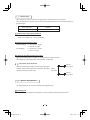
7
3 External Sync
When using the unit with an external sync signal to EXT. SYNC terminal on the rear panel.
When the external sync signal is input, the camera automatically switches its sync from the internal sync to
the external sync.
EXT. SYNC input
Operation
SYNC
External sync with SYNC
䋨1䋩
䋩 External sync signal input conditions
SYNC 䋨75㱅 unbalanced䋩 䋺 0.6 V (p-p) standard
2
External sync frequency range
(59.94 Hz Setting)
H : 33.716 䌫Hz 㫧 35 ppm
V : 59.94 Hz 㫧 35 ppm
(50 Hz Setting)
H : 28.125 䌫Hz 㫧 35 ppm
V : 50 Hz 㫧 35 ppm
3
Using the unit with external sync signal
Adjust H (Horizontal) phase if necessary to match the output of multiple cameras.
When adjusting H (Horizontal) phase, refer to the item “7.2 (6) SYNC”.
3. 1
H (Horizontal) phase adjustment
External
Sync. signal
Observe the external sync signal and the video signal output
waveform of the unit with a dual trace oscilloscope, and adjust
H phase so that the H phases match.
Match
the phase.
Camera
Sync. output
7
4 Synchro. Scan Operation
The shutter speed can be set by the horizontal scanning period (1H).
1
Setting by 1H
1/1125H to 560/1125H stands for the setting by the 1H and the shutter speed can be set by the 1H.
31
IK-HD1E_EN.indd 31
2007/11/20 9:33:21
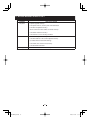
8. BEFORE MAKING SERVICE CALL
Symptom
No picture
Items to be checked
䍃 Is power supplied correctly?
䍃 Is the power switch on, and the power LED illuminated?
䍃 Is the lens iris adjusted correctly?
䍃 Are the camera and video cables connected correctly?
䍃 Is the shutter mode set correctly?
䍃 Is the monitor on, and in working condition?
Poor color
䍃 Is the monitor adjusted correctly?
䍃 Is the white balance of the camera adjusted correctly?
(in modes other than automatic tracking)
䍃 Is the matrix color correction set correctly?
䍃 Is the illumination sufficient?
Noise appears
䍃 Is the camera cable connected securely?
32
IK-HD1E_EN.indd 32
2007/11/20 9:33:21
9. SPECIFICATIONS
* These conditions are only satisfied when the camera control unit is connected to camera head model # IK-HD1H.
Power supply
Power consumption
Pick-up system
Image sensor
Output pixels
Scanning system
Scan frequency
Sync system
Horizontal resolution
Vertical resolution
Sensitivity
Minimum illumination
SN ratio
Ambient temperature
Ambient humidity
Weight
External dimension
Scene file(user memories)
White balance
Gain
Output signal
12V DC㫧10%
Approx. 10.3 W (including a camera head)
RGB, 3CCD, Micro prism system
1/3 inch, IT䋭CCD
Horizontal : 1920, Vertical : 1080
2䋺1 interlace
[59.94 Hz setting] Horizontal : 33.716 kHz, Vertical : 59.94 Hz
[50 Hz setting]
Horizontal : 28.125 kHz, Vertical : 50 Hz
Internal/External (Automatic switching)
800TV lines standard
800TV lines standard
F6.8䋨59.94 Hz setting, 2000 lx, 3000 K䋩, F7.4䋨50 Hz setting, 2000 lx, 3000 K䋩
13 lx䋨59.94 Hz setting, F2.2, sensitivity䋫18 dB䋩,
11 lx䋨50 Hz setting, F2.2, sensitivity䋫18 dB䋩
56 dB standard (gain 0 dB, DNR OFF)
0 㷄 to 40 㷄 (32㫦F to 104 㫦F)
Less than 90%
Approx. 730 g (1.61 lbs)
110(W)㬍40(H)㬍186(D) mm
(4.33”(W)㬍1.57”(H)㬍7.32”(D))
(excluding protrusions)
5 files (A, B, C, D, E)
ATW䋨Automatic tracing balance䋩, AWB䋨Automatic white balance䋩
MANUAL䋨Manual䋩
AUTO䋨Automatic gain control䋩, MANUAL䋨Manual䋩, OFF䋨0 dB䋩
Y/PB /PR or RGB : 0.7 V (p-p) standard 75 㱅 unbalanced, BNC connector
HD-SDI (SMPTE 292M) : 0.8 V (p-p) standard 75 㱅 unbalanced, BNC connector
External sync input
HD SYNC 0.6 V (p-p) 75 㱅 unbalanced BNC connector
[59.94 Hz setting] Horizontal : 33.716 kHz 㫧35 ppm, Vertical : 59.94 Hz 㫧35 ppm
[50 Hz setting]
Horizontal : 28.125 kHz 㫧35 ppm, Vertical : 50 Hz 㫧35 ppm
Sync signal output
SYNC : 0.6 V 㫧 0.1 V 75 㱅 unbalanced BNC connector
[59.94 Hz setting] Horizontal : 33.716 kHz 㫧35 ppm, Vertical : 59.94 Hz 㫧35 ppm
[50 Hz setting]
Horizontal : 28.125 kHz 㫧35 ppm, Vertical : 50 Hz 㫧35 ppm
Interface
Optional parts
Serial data interface䋨RS-232C䋩
IK-HD1H 䋨1/3 inch 3CCD camera head䋩
EXC䋭HD03 (Approx. 3 m (118”) Camera cable)
EXC䋭HD06 (Approx. 6 m (236”) Camera cable)
EXC䋭HD10 (Approx. 10 m (394”) Camera cable)
EXC䋭HD30 (Approx. 30 m (1181”) Camera cable)
Design and specifications are subject to change without notice.
33
IK-HD1E_EN.indd 33
2007/11/20 9:33:21
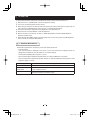
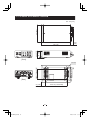
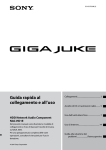
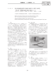
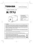
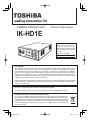
10. EXTERNAL APPEARANCE DIAGRAM
㪈㪈㪇㩷㪲㪋㪅㪊㪊㪴
Unit : mm [inch]
㪈㪏㪅㪏㪊
㪲㪇㪅㪎㪋㪴
㪋㪇㩷㪲㪈㪅㪌㪏㪴
㪋㪋㪅㪍㩷㪲㪈㪅㪎㪍㪴
㪈㪏㪍㩷㪲㪎㪅㪊㪉㪴
[Front]
[Rear]
㪍㪉㫧㪇㪅㪈㩷㪲㪉㪅㪋㪋㫧㪇㪅㪇㪇㪋㪴
㪋㪄㪤㪊㩷㪙㪛
㪈㪊㪐㫧㪇㪅㪈㪌㩷㪲㪌㪅㪋㪎㪉㫧㪇㪅㪇㪇㪍㪴
㪉㪎㩷㪲㪈㪅㪇㪍㪴
34
IK-HD1E_EN.indd 34
2007/11/20 9:33:21
Limited Warranty – TOSHIBA CCD Camera
The Imaging Systems Division of Toshiba America Information Systems, Inc. ("ISD") makes the following limited warranties
with regard to this CCD Camera ("Product"). These limited warranties extend to the Original End-User ("You[r]").
One (1) Year Limited Warranty of Labor and Parts
ISD warrants that this Product will perform in accordance with specifications for a period of one (1) year from the date of
purchase by the Original End-User. During this one (1) year period, ISD will repair or replace the Product, if it does not
perform as warranted. In order to take advantage of this Limited Warranty, You must: (a) deliver the Product to an ISD
Authorized Service Provider ("ASP"); and (b) pay all transportation and insurance charges for shipment of the Product to the
ASP. ISD reserves the right to substitute factory refurbished parts in place of those in need of repair.
Instruction Manual (Owner’s Manual):
You should read the Instruction Manual (Owner’s Manual) thoroughly before operating this Product. Before seeking warranty
service, you should check the troubleshooting guide in the Instruction Manual (Owner’s Manual) and follow the instructions to
correct the problem.
Your Responsibilities
This Limited Warranty is subject to the following conditions:
1. You must provide the bill of sale or proof of purchase at the time that warranty service is required.
2. You must notify an ASP within thirty (30) days after You discover that the Product does not perform in accordance with
specifications during the Limited Warranty period.
3. All warranty servicing of this product must be made by an ISD Authorized Service Provider.
4. You must pack the Product in its original carton using the original packing material, then insert the original carton
containing the Product into another carton with additional packing material before shipping the Product to an ASP.
DISCLAIMERS:
ALL OTHER EXPRESS OR IMPLIED WARRANTIES ON THIS PRODUCT, INCLUDING THE IMPLIED WARRANTIES OF
MERCHANTABILITY AND FITNESS FOR A PARTICULAR PURPOSE, ARE HEREBY DISCLAIMED. SOME STATES DO
NOT ALLOW THE EXCLUSION OF IMPLIED WARRANTIES OR LIMITATIONS ON HOW LONG AN IMPLIED WARRANTY
LASTS, SO THE ABOVE LIMITATIONS MAY NOT APPLY TO YOU.
IF THIS PRODUCT IS NOT IN GOOD WORKING ORDER AS WARRANTED ABOVE, YOUR SOLE AND EXCLUSIVE
REMEDY SHALL BE THE REPAIR OR REPLACEMENT OF THE PRODUCT. IN NO EVENT WILL ISD OR ITS PARENT
COMPANY OR ANY ASP BE LIABLE TO YOU OR ANY THIRD PARTY FOR ANY DAMAGES IN EXCESS OF THE
PURCHASE PRICE OF THE PRODUCT. THIS LIMITATION APPLIES TO DAMAGES OF ANY KIND, INCLUDING ANY
DIRECT OR INDIRECT DAMAGES, LOST PROFITS, LOST SAVINGS OR OTHER SPECIAL, INCIDENTAL, EXEMPLARY
OR CONSEQUENTIAL DAMAGES, WHETHER FOR BREACH OF CONTRACT, TORT OR OTHERWISE, OR WHETHER
ARISING OUT OF THE USE OF OR INABILITY TO USE SUCH PRODUCT, EVEN IF TAIS, ITS PARENT COMPANY, OR
AN ASP HAS BEEN ADVISED OF THE POSSIBILITY OF SUCH DAMAGES OR OF ANY CLAIM BY ANY OTHER PARTY.
SOME STATES DO NOT ALLOW THE EXCLUSION OR LIMITATION OF INCIDENTAL OR CONSEQUENTIAL DAMAGES
FOR SOME PRODUCTS, SO THE ABOVE LIMITATIONS OR EXCLUSIONS MAY NOT APPLY TO YOU.
THIS WARRANTY GIVES YOU SPECIFIC LEGAL RIGHTS, AND YOU MAY ALSO HAVE OTHER RIGHTS WHICH MAY
VARY FROM STATE TO STATE.
THIS LIMITED WARRANTY SHALL BE VOID IF THE PRODUCT OR PARTS HAVE BEEN SUBJECTED TO MISUSE,
ABUSE, ACCIDENT, IMPROPER INSTALLATION, IMPROPER MAINTENANCE, OR USE IN VIOLATION OF ISD’S
WRITTEN INSTRUCTIONS, OR WHERE THE PRODUCT HAS BEEN ALTERED OR MODIFIED WITHOUT ISD’S PRIOR
AUTHORIZATION, OR UPON THE REMOVAL OR ALTERATION OF ISD’S FACTORY SERIAL NUMBER. LABOR
SERVICE CHARGES FOR PRODUCT INSTALLATION, SET UP AND ADJUSTMENT OF CONTROLS ARE NOT
COVERED BY THIS LIMITED WARRANTY.
How to Obtain Warranty Service – Step-By-Step Procedures:
To obtain warranty service, You should:
1. Contact an ASP for warranty service within thirty (30) days after the Product fails to comply with specifications.
2. Arrange for shipment of the Product to an ASP.
3. Securely pack the Product as described above, insure the carton, and include a letter explaining the problem and a copy
of the bill of sale or proof of purchase.
4. Prepay all transportation and insurance costs.
Questions? If you have any questions, please check ISD’s Web Site or send an e-mail as follows:
Web Site: http://www.toshiba.com/taisisd/indmed
E-mail: [email protected]
No person, agent, distributor, dealer, authorized service provider, or company is authorized to change, modify, or extend the
terms of this Limited Warranty in any manner whatsoever. The time within which an action must be commenced to enforce
any obligation of ISD arising under this Limited Warranty or under any statute, or law of the United States or any state thereof,
is hereby limited to one (1) year from the date You discover or should have discovered the problem. This limitation does not
apply to implied warranties arising under state law. Some states do not permit limitation of the time within which You may bring
an action beyond the limits provided by state law, so the above provision may not apply to You. This Limited Warranty gives
You specific legal rights and You may also have other rights which vary from state to state.
TOSHIBA AMERICA INFORMATION SYSTEMS, INC.
Imaging Systems Division
9740 Irvine Boulevard, Irvine, CA 92618-1697
Copyright © 2007 Toshiba America, Inc. All rights reserved.
IK-HD1E_EN.indd 35
2007/11/20 9:33:22