1
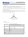
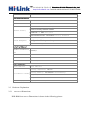
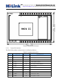
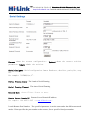
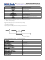
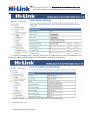
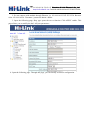
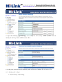
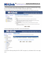
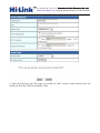
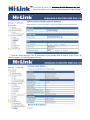
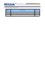
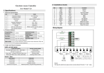
深圳市海凌科电子有限公司 Shenzhen Hi-Link Electronic Co.,Ltd Http://www.hlktech.com Tel:0755-83575155 Fax:0755-83575189 Shenzhen Hi-Link ElectronicTechnology co. co.,, Ltd HLK-RM04 User Manual ETHERNET WIFI Full Function Serial Network/Wireless Module 1 BRIEF INTRODUCTION........................................................................................................................................ 3 .............................................................................................................................................................. 3 2 SUMMARIZE SUMMARIZE.............................................................................................................................................................. ..............................................................................................................................................................3 深圳市海凌科电子有限公司 Shenzhen Hi-Link Electronic Co.,Ltd Http://www.hlktech.com Tel:0755-83575155 Fax:0755-83575189 2.1 TECHNICAL SPECIFICATIONS.................................................................................................................................. 3 2.2 HARDWARE EXPLANATION.................................................................................................................................... 4 2.2.1 Mechanical Dimensions..................................................................................................................................4 6 3 QUICK START .......................................................................................................................................................... ..........................................................................................................................................................6 3.1 RESTORE FACTORY SETTINGS................................................................................................................................. 6 3.2 CONFIGURATE NETWORK PARAMETER................................................................................................................... 6 3.3 CONFIGURATE SERIAL NETWORK PARAMETER........................................................................................................ 6 ................................................................................................... 7 4 PARAMETER CONFIGURATION DIRECTION DIRECTION................................................................................................... ...................................................................................................7 .......................................................................................................................................... 7 5 WEB CONFIGURATION CONFIGURATION.......................................................................................................................................... 5.1 WEB NETWORK CONFIGURATION.......................................................................................................................... 7 5.2 WEB SERIAL CONFIGURATION...............................................................................................................................7 ........................................................................................................ 8 6 SERIAL AT COMMAND CONFIGURATION CONFIGURATION........................................................................................................ 6.1 ACCESS TO AT COMMAND MODE............................................................................................................................8 6.2 AT COMMAND........................................................................................................................................................9 ............................................................................................................................ 9 7 RESTORE FACTORY SETTINGS SETTINGS............................................................................................................................ ............................................................................................................................9 .......................................................................................................................................... 10 8 FIRMWARE UPGRADE UPGRADE.......................................................................................................................................... ..........................................................................................................................................10 ............................................................................................. 11 9 TYPICAL APPLICATION NETWORK SETTINGS SETTINGS............................................................................................. 9.1 SERIAL TO ETHERNET........................................................................................................................................... 11 9.2 SERIAL TO WIFI(AP).........................................................................................................................................12 9.3 SERIAL TO WIFI(CLIENT)................................................................................................................................. 14 ................................................................................................... 18 APPENDIX A DOCUMENT REVISION RECORD RECORD................................................................................................... 深圳市海凌科电子有限公司 Shenzhen Hi-Link Electronic Co.,Ltd Http://www.hlktech.com Tel:0755-83575155 Fax:0755-83575189 1 Brief Introduction HLK-RM04 is a new low-cost embedded UART-ETH-WIFI module (serial port - Ethernet - Wireless network) developed by Shenzhen Hi-Link ElectronicTechnology co., Ltd This product is an embedded module based on the universal serial interface network standard, built-in TCP / IP protocol stack, enabling the user serial port, Ethernet, wireless network (wifi) interface between the conversions. Through the HLK-RM04 module, the traditional serial devices do not need to change any configuration; data can be transmitted through the Internet network. Provide a quick solution for the user’s serial devices to transfer data via Ethernet. Serial Com WIFI(Client/AP) Ethernet Picture1.F-structure 2 2.1 Summarize Technical Specifications Table2-1Technical Specifications Network standard Wireless transmission rate wireless:IEEE 802.11n、IEEE 802.11g、IEEE 802.11b wired:IEEE 802.3、IEEE 802.3u 11n: maximum up to 150Mbps 11g: maximum up to 54Mbps 11b: maximum up to 11Mbps Tracks number 1-14 Frequency range 2.4-2.4835G Emission power 12-15DBM Interface 1 个 10/100Mbps LAN/WAN multiplex interface、interface Antenna Antenna type Onboard antenna / External Antenna 深圳市海凌科电子有限公司 Shenzhen Hi-Link Electronic Co.,Ltd Http://www.hlktech.com Tel:0755-83575155 Fax:0755-83575189 Functional Parameters WIFI work mode Client/AP/Router WDS Function Support WDS wireless bridge connection Wireless MAC address filtering Wireless security Wireless security function switch 64/128/152 bit WEP encryption WPA-PSK/WPA2-PSK、WPA/WPA2 security mechanism Remote Web management Network management Configuration file import and export WEB software upgrade Serial to Ethernet Maximum transmission rate 230400bps TCP connection Max connection number>20 UDP connection Max connection number>20 Serial baud rate 50~230400bps Other Parameters Status indicator Status indicator Operating temperature:-20-70℃ Operating humidity:10%-90%RH(noncondensing) Environmental standard Storage temperature:-40-80℃ Storage humidity:5%-90%RH(noncondensing) Additional properties Frequency bandwidth optional:20MHz、40MHz,Auto 2.2 Hardware Explanation 2.2.1 Mechanical Dimensions HLK-RM04 Mechanical Dimensions is shown in the following picture: 深圳市海凌科电子有限公司 Shenzhen Hi-Link Electronic Co.,Ltd Http://www.hlktech.com Tel:0755-83575155 Fax:0755-83575189 Picture2.Dimensions Unit:mm 2.2.1.1 Contact Pin Interface The Pin of this product as shown above is defined as follows: Table2-2 module pin interface No. Function 1 VDD5V 2 Direction Explanation A 5 Power input GND GND Power ground 3 GND G Serial sending 4 3.3V I 3.3V power output 5 LINK1 I/O 6 USB_P USB signal 7 USB_M USB signal 8 I2S_SD I2C DATA/GPIO 9 I2S_CLK I2C CLK/GPIO 10 GIOP0 I/O Universal GPIO 11 TXOP1 I/O Net gape 1 TX-P Net gape 1 LED indicte 深圳市海凌科电子有限公司 Shenzhen Hi-Link Electronic Co.,Ltd Http://www.hlktech.com Tel:0755-83575155 Fax:0755-83575189 3 3.1 12 TXON1 I/O Net gape 1 TX-N 13 RXIP2 I/O Net gape 2 RX-P 14 RXIN2 I/O Net gape 2 RX-N 15 RXIN1 I/O Net gape 1 RX-P 16 RXIP1 I/O Net gape 1 RX-P 17 TXON2 I/O Net gape 2 TX-N 18 TXOP2 I/O Net gape 2 TX-P 19 RTS_N I All function serial RTS 20 UART_RX I Simple serial RX 21 UART_TX O Simple serial TX 22 RXD I All function serial RX 23 LINK2 I/O 24 CTS_N O All function serial CTS 25 RIN I GPIO 26 TXD O All function serial TX 27 1.8V Power Out Net gape 1.8V output 28 VDD5V Power In 5V input Net gape 2 LED I/O indicte Quick Start Restore factory settings In order to ensure that all of configuration process is correct, bringing the module to restore the factory settings firstly. Factory mode, the module can skip this step. Above 5V (500mA) to power the module on the power, wait about 2.5 minutes for the system to start, after the start completion, pulled ES / RST pin down and make it surpass Trst, release ES / RST pin, the system will automatically restart. After rebooting, the system is already in Factory mode. 3.2 Configurate network parameter Set the PC to static IP mode and then connect it with the module via Ethernet or wifi. The IP address is set to 192.168.16.100/255.255.255.0, gateway 192.168.16.254. The (wifi default ssid and the default password, see this document.) open the browser http://192.168.16.254, enter the web configuration page, default user name and password is admin / admin. Modify the network parameters through the web. Now, the module’s IP address is 192.168.16.254. Configuration details can be seen in 5.1. 深圳市海凌科电子有限公司 Shenzhen Hi-Link Electronic Co.,Ltd Http://www.hlktech.com Tel:0755-83575155 Fax:0755-83575189 3.3 Configurate serial network parameter Opens the browser http://192.168.16.254/ser2net.asp, enter the serial-to-network web configuration page. Configure the serial-to-network parameters as needed through a web page. Configuration details can be seen in 5.2. 4 Parameter configuration direction The module provides two ways for the configuration parameters: 1.Web page; 2. Serial AT command. Access to WEB configuration page requires the confirmation of the module’s IP addresses, as well as the user name and password that authenticated by WEB. Configurating parameters through the serial port AT command needs to make the module into the AT command mode first. 5 WEB configuration Through the correct module address,you can access to the WEB configuration page. 5.1 WEB network configuration Detailed information can refer to<<HI-LINK Router User manual>> 5.2 WEB serial configuration Serial Web configuration page(ser2net.asp)is as follows: 深圳市海凌科电子有限公司 Shenzhen Hi-Link Electronic Co.,Ltd Http://www.hlktech.com Tel:0755-83575155 Fax:0755-83575189 Current shows the current configuration , Updated shows the current revision parameters。Submit submit the revision. Serial Configure:Serial configuration.fomat:Baud rate, data bits, parity bit, stop bit. For example:“115200,8,n,1”. Serial Framing Lenth:The Lenth of Serial Framing Serial Framing Timeout:The time of Serial Framing Network Mode:choose Client、Server or none。 Remote Server Domain/IP:Remote Server Domain/IP address For exmpale:192.168.11.245 or www.hlktech.com . Locale/Remote Port Number:The specified parameter is not the same under the different network modes. Client specifies the port number on the remote, Server specified local port number. 深圳市海凌科电子有限公司 Shenzhen Hi-Link Electronic Co.,Ltd Http://www.hlktech.com Tel:0755-83575155 Fax:0755-83575189 Network Protocol:Use tcp or udp Protocol Network Timeout:Under the server network mode, no data transmission within the timeout period, the connection will be disconnected. 0 specifies never disconnected. 6 Serial AT command configuration 6.1 Access to AT command mode Module in network fault, such as fault allocation situation will automatically exit the transparent transmission mode, enter AT instruction mode. In any condition, keep ES/RST feet low level of time but more than Tes and less than Trst, the module will enter AT instruction mode immediately. >Tes <Trst V(ES/RST) t AT Command . 6.2 AT Command In AT mode, you can configurate the system parameters through the serial port AT instruction. Instruction format is as follows: At+[command]=[value]\r According to the different command, module will return a different return value. For example:"at+remoteip=192.168.11.133\n" set remote ip address as 192.168.11.133. For example:"at+remoteip=?\n" Inquiry remote ip address. At command is as follows: ver remoteip remoteport The version of module Remote server domain name or IP address The local or distal port number 深圳市海凌科电子有限公司 Shenzhen Hi-Link Electronic Co.,Ltd Http://www.hlktech.com Tel:0755-83575155 Fax:0755-83575189 remotepro Network Protocol type timeout Network timeout mode Network mode uart Serial port configuration uartpacklen Serial group frame length uartpacktimeout Serial framing time save Save the configuration and start service reconn Restart services Parameter definition is consistent with the web configuration parameter. 7 Restore factory Settings Support the following ways to restore the factory settings 1. Through the Web page. 2 By keeping the ES/RST pin low level time greater than Trst. V(ES/RST) >Trst t Reset to Default. Factory setting parameter values, see the following list: IP address 192.168.16.254 Web username/password admin/admin Wifi password 0000000000 Serial Configure 115200,8,n,1 Serial Framing Lenth 64 Serial Framing Timeout 10 Network Mode Client Remote Server Domain/IP: 192.168.11.245 Locale/Remote Port Number 8080 Network Protocol Udp Network Timeout 0 深圳市海凌科电子有限公司 Shenzhen Hi-Link Electronic Co.,Ltd Http://www.hlktech.com Tel:0755-83575155 Fax:0755-83575189 Tes 100ms Trst 5s 8 Firmware upgrade 1. Restore the factory value. 2. Pc can connect with module through Ethernet, ip: 192.168.16.123/255.255.255.0. Browser visits 192.168.16.254. Username / password: admin / admin. 3. Open the following page. Select the appropriate firmware, click apply upgrades. Wait about 3 minutes. Can not cut out the upgrade process, otherwise it may cause damage to the module. 9 Typical application network settings This section will give some simple examples to use the different functions of a typical configuration. 9.1 Serial to Ethernet 1. Restore factory value setting. 2. Pc can connect with module through Ethernet, ip: 192.168.16.123/255.255.255.0. Browser visits 192.168.16.254. Username / password: admin / admin. 3. Open the following page, click on the RADIO OFF button to turn off wifi function, shown as below. Clicks APPLY to take effect. 深圳市海凌科电子有限公司 Shenzhen Hi-Link Electronic Co.,Ltd Http://www.hlktech.com Tel:0755-83575155 Fax:0755-83575189 4. Open the following page. This page allows you to modify the the LAN port parameters. Set Ethernet ip address, gateway, dns server information, click apply to take effect. 5. At this moment, you must use new ip address to access the web page. 9.1 Serial to wifi(ap) 1. Restore factory value setting. 深圳市海凌科电子有限公司 Shenzhen Hi-Link Electronic Co.,Ltd Http://www.hlktech.com Tel:0755-83575155 Fax:0755-83575189 2. Pc can connect with module through Ethernet, ip: 192.168.16.123/255.255.255.0. Browser visits 192.168.16.254. Username / password: admin / admin. 3. Open the following page, dhcp type opens the server function. Click APPLY enable. This page allows you to modify the the LAN port parameters. 4. Open the following page. Through this page, you can modify wifi basic configuration 深圳市海凌科电子有限公司 Shenzhen Hi-Link Electronic Co.,Ltd Http://www.hlktech.com Tel:0755-83575155 Fax:0755-83575189 5. Open the following page. This page can modify the wifi security related function. You can modify the wifi key. Clicks APPLY to take effect. 6. At this point, connected to the module by other wifi devices. Module IP: 192.168.16.254. 9.2 Serial to wifi(client) 1. Restore factory value setting. 深圳市海凌科电子有限公司 Shenzhen Hi-Link Electronic Co.,Ltd Http://www.hlktech.com Tel:0755-83575155 Fax:0755-83575189 2. Pc can connect with module through Ethernet, ip: 192.168.16.123/255.255.255.0. Using Browser to access to 192.168.16.254. Username / password: admin / admin. 3. Open the following page, set to Ethernet Converter mode.Click on the APPLY to take effect. 4. Open the following page.Click APPLY to increase AP information. 5. Pop-up the following dialog box.Fill in SSID, encryption, key information.Click on the apply effect. 深圳市海凌科电子有限公司 Shenzhen Hi-Link Electronic Co.,Ltd Http://www.hlktech.com Tel:0755-83575155 Fax:0755-83575189 6. Open the following page.This page can modify the WiFi security related function.You can modify the WiFi key.Click on the APPLY effect. 深圳市海凌科电子有限公司 Shenzhen Hi-Link Electronic Co.,Ltd Http://www.hlktech.com Tel:0755-83575155 Fax:0755-83575189 7. Open the following page, view IP information of the module.Wan IP address is the ip.If no IP address appears, it means disconnected to AP. 深圳市海凌科电子有限公司 Shenzhen Hi-Link Electronic Co.,Ltd Http://www.hlktech.com Tel:0755-83575155 Fax:0755-83575189 Appendix A document revision record Version Revision range number 1.00 Draft version Date 2012-9-10