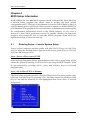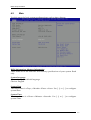
1
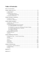
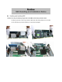
ROBO-8780VG2A Single Host Board User's Manual Version 1.0 Copyright © Portwell, Inc., 2012 All rights reserved. All other brand names are registered trademarks of their respective owners. Table of Contents How to Use This Manual Chapter 1 System Overview.......................................................................................................1-1 1.1 Introduction ....................................................................................................... 1-1 1.2 Check List........................................................................................................... 1-2 1.3 Product Specification........................................................................................ 1-2 1.3.1 Mechanical Drawing................................................................................ 1-5 1.4 System Architecture.......................................................................................... 1-6 Chapter 2 Hardware Configuration ...........................................................................................2-1 2.1 Jumper Setting ................................................................................................... 2-1 2.2 Connector Allocation........................................................................................ 2-3 Chapter 3 System Installation....................................................................................................3-1 3.1 Intel LGA-1155 Processor ................................................................................ 3-1 3.2 Main Memory .................................................................................................... 3-4 3.3 Installing the Single Board Computer............................................................ 3-5 3.3.1 Intel® BD82H61 PCH Chipset ............................................................... 3-5 3.3.2 Intel® Core i processors integrated Graphics Engine......................... 3-5 3.3.3 Intel® Gigabit Ethernet Controller ........................................................ 3-5 3.3.4 Audio Controller ...................................................................................... 3-5 3.3.5 USB3.0 Controller..................................................................................... 3-5 3.4 Clear CMOS Operation .................................................................................... 3-6 3.5 WDT Function ................................................................................................... 3-6 3.6 GPIO.................................................................................................................... 3-8 Chapter 4 BIOS Setup Information............................................................................................4-1 4.1 Entering Setup -- Launch System Setup ........................................................ 4-1 4.2 Main .................................................................................................................... 4-2 4.3 Advanced ........................................................................................................... 4-3 4.4 Boot ................................................................................................................... 4-27 4.5 Security ............................................................................................................. 4-32 4.6 Security ............................................................................................................. 4-34 4.7 Save & Exit ....................................................................................................... 4-35 Chapter 5 Troubleshooting ........................................................................................................5-1 5.1 Hardware Quick Installation........................................................................... 5-1 5.2 BIOS Setting ....................................................................................................... 5-2 5.3 FAQ ..................................................................................................................... 5-3 Appendix A Appendix B How to Use This Manual The manual describes how to configure your ROBO-8780VG2A series system to meet various operating requirements. It is divided into five chapters, with each chapter addressing a basic concept and operation of Single Host Board. Chapter 1 : System Overview. Presents what you have in the box and give you an overview of the product specifications and basic system architecture for this series model of single host board. Chapter 2 : Hardware Configuration. Shows the definitions and locations of Jumpers and Connectors that you can easily configure your system. Chapter 3 : System Installation. Describes how to properly mount the CPU, main memory and Compact Flash to get a safe installation and provides a programming guide of Watch Dog Timer function. Chapter 4 : BIOS Setup Information. Specifies the meaning of each setup parameters, how to get advanced BIOS performance and update new BIOS. In addition, POST checkpoint list will give users some guidelines of trouble-shooting. Chapter 5 : Troubleshooting. Provides various useful tips to quickly get ROBO-8780VG2A series running with success. As basic hardware installation has been addressed in Chapter 3, this chapter will basically focus on system integration issues, in terms of backplane setup, BIOS setting, and OS diagnostics. The content of this manual is subject to change without prior notice. These changes will be incorporated in new editions of the document. Portwell may make supplement or change in the products described in this document at any time. Updates to this manual, technical clarification, and answers to frequently asked questions will be shown on the following web site : http://www.portwell.com.tw/. Notice SBC Handling and Installation Notice Handling and Installing SBC Caution: Do not just hold any single side of the SBC; hold evenly on both sides! z Heavy processor cooler may bend the SBC when SBC being held just on one side. z The bending may cause soldering or components damaged. Fix your SBC in System Caution: Suggest your S.I or vendor to use a metal bracket to hold/fix the desktop or server grade SBC to avoid the vibration damage during transportation. Heavy processor cooler may bend the SBC when systems are during transportation without any holder. Example: z 4U chassis : Î Use L type mental or plastic or rubber bracket to hold SBC. z 2U or 1U chassis: a mental bracket on the bottom of chassis to balance and support SBC from bending. System Overview Chapter 1 System Overview 1.1 Introduction ROBO-8780VG2A, the PICMG 1.0 SBC (Single Board Computer) supports the Intel® Core i7/i5/i3 and Pentium processors in LGA1155 package. The attractive Core i3/i5/i7 and Pentium family processors delivers not only high computing power but also high graphic performance. That makes the system more powerful. ROBO-8780VG2A adopts Intel® entry level H61 PCH that supports up to Intel® Core i7 processor and 16GB DDR3-1333 system memory. Intel® Core i series processors equipped Intel® integrated Graphics Engine, that supports DirectX10.1, Shader Model 4.0 and OpenGL 3.0. ROBO-8780VG2A supports dual Gigabit Ethernet port, four SATA 300 ports, ten USB 2.0 ports, One RS232 port, one RS232/422/485 port selectable by jumper, one parallel port, and one FDD port, GPIO and Watchdog timer as usual. Dual USB 3.0 ports support also built on ROBO-8780VG2A. In addition, ROBO-8780VG2A supports multiple displays, such as VGA port up to 2048 x 1536 resolution, one DVI-D port up to 1920 x 1200 resolution and so on. ROBO-8780VG2A is an ideal entry level PICMG 1.0 SBC with higher graphic performance and computing power for the market demand. ROBO-8780VG2A brief specifications: z Support Intel® Core i3/i5/i7 and Pentium processor in an LGA1155 socket z Dual 240-pin DDR3 SDRAM DIMM socket, support for DDR3 1066/1333 DIMMs, up to 16GB system memory z Intel® Core i processors integrated graphics engine z Equipped dual Gigabit Ethernet port z Support two COM ports, four SATA 300 ports, ten USB 2.0 ports (dual ports on bracket), and dual USB 3.0 ports z Support dual display by VGA (on bracket) and DVI-D ROBO-8780VG2A User’s Manual 1-1 System Overview 1.2 Check List The ROBO-8780VG2A package should cover the following basic items: 9One ROBO-8780VG2A single board computer 9Two SATA 300 cable 9One 4-pin ATX power control cable for backplane connection 9One FDD and Parallel ports with bracket 9Dual COM port cable with bracket 9One Installation Resources CD-Title If any of these items is damaged or missing, please contact your vendor and keep all packing materials for future replacement and maintenance. 1.3 Product Specification z Main processor - Intel® Core i3/i5/i7 and Pentium Processor in LGA1155 package z BIOS - AMI uEFI BIOS z Main Memory - Support dual-channel & signal channel DDR3 memory interface - Non-ECC, non-buffered DIMMS only - Two DIMM sockets support 1,066/1333 DDR3-SDRAM up to 16GB System Memory z Chipset -Intel® H61 PCH z Bus Interface -Follow PICMG 1.0 Rev 2.0 standard (32-bit PCI and 16-bit ISA) -Fully complies with PCI Local Bus specification V2.2 (support 4 master PCI slots via ITE 8892E PCIEx1 to PCI bridge) -Support ISA function via Fintek LPC to ISA bridge F85226FG z Floppy Drive Interface -Support one FDD port up to two floppy drives and 5-1/4"(360K, 1.2MB), 3-1/2" (720K, 1.2MB, 1.44MB, 2.88MB) diskette format and 3-mode FDD z Serial Ports -Support two serial ports, one is RS232, the other is RS232/422/485 selectable by jumper. z Parallel Port -Support one parallel port with SPP, EPP and ECP modes z USB Interface - Support ten USB 2.0 (Universal Serial Bus) ports for high-speed I/O peripheral devices (Dual USB ports on bracket) and dual on-board USB 3.0 ports ROBO-8780VG2A User’s Manual 1-2 System Overview z Audio Interface - On board Audio codec via HD Audio interface - One optional Audio kit PA-M1AU for Mic in/Line in/Line out. z PS/2 Mouse and Keyboard Interface - Support one on-board connector for PS/2 keyboard/mouse connection z ATX Power Control Interface - One 8-pin header to support ATX power control via backplane z Auxiliary I/O Interfaces - System reset switch, external speaker, and HDD active LED, etc z Real Time Clock/Calendar (RTC) - Support Y2K Real Time Clock/Calendar with battery backup for 7-year data retention z Watchdog Timer - Support WDT function through software programming for enable/disable and interval setting - Generate system reset z SATA - Four SATA 300 ports (w/o RAID function) z On-board VGA - Intel Core i processors integrated Graphics device z Display - One VGA port, up to 2048 x 1536 - One DVI-D port up to 1920x1200 z On-board Ethernet LAN - One Intel 82579LM and one Intel 82583V Gigabit controller to support dual RJ-45 connector on brakcet z High Driving GPIO - Support 8 programmable high driving GPIO z Cooling Fans - Support one 4-pin and one 3-pin headers for CPU, and System fans z System Monitoring Feature - Monitor CPU temperature, system temperature and major power sources, etc z Bracket - Support dual Ethernet port with 2 indicators, dual USB ports, and one CRT port z Outline Dimension (L X W): - 338.5mm (13.33”) X 122mm (4.8”) z Power Requirements: +12V (CPU) @5.3A +12V (System) @ 6.5A +5V (System) @4.7A ROBO-8780VG2A User’s Manual 1-3 System Overview Configuration: System Configuration CPU Type SBC BIOS Memory Intel® Core i7-2600 [email protected] L3:8M VGA Card VGA Driver LAN Card LAN Driver Onboard Intel ® Sandy Bridge HD Graphics Family Audio Card Audio Driver Chip Driver USB 3.0 Driver SCSI Card SCSI HDD SATA HDD Onboard Realtek ALC886 High Definition Audio Compact Flash FDD N/A CDROM Power Supply Pioneer K BXCN2 Back plane 14A7-A Portwell, Inc. ROBO-8780VG2A BIOS Rev.:R1.00.E1(06192012) Apacer UNB PC3-8500 2G*1 (ELPIDA J1108BFBG-DJ-F) Intel ® Sandy Bridge HD Graphics Family Ver:8.15.10.2622 Onboard Intel ® 82579LM/82583V Gigabit Network Connection Intel ® 82579LM/82583V Gigabit Network Connection Ver:11.15.12.0/11.14.48.0 Realtek ALC886 High Definition Audio Ver:6.0.1.6649 Intel® Chipset Device Software Ver:9.3.0.1019 Renesas Electronics USB3.0 Host Controller Ver:2.0.4.0 Adaptec 29160LP Seagate ST39173W 20G Seagate ST3160815AS 160G TEAC FD-235HF FSP-FSP350-60GLC z Operating Temperature: 0°C ~ 60°C (23°F ~ 140°F) z Storage Temperature: -20°C ~ 80°C z Relative Humidity: 5% ~ 90%, non-condensing ROBO-8780VG2A User’s Manual 1-4 System Overview 1.3.1 Mechanical Drawing ROBO-8780VG2A User’s Manual 1-5 System Overview 1.4 System Architecture All of details operating relations are shown in ROBO-8780VG2A series System Block Diagram. ROBO-8780VG2A series System Block Diagram ROBO-8780VG2A User’s Manual 1-6 Hardware Configuration Chapter 2 Hardware Configuration This chapter gives the definitions and shows the positions of jumpers, headers and connectors. All of the configuration jumpers on ROBO-8780VG2A are in the proper position. The default settings shipped from factory are marked with an asterisk ( ). 2.1 Jumper Setting In general, jumpers on the single board computer are used to select options for certain features. Some of the jumpers are designed to be user-configurable, allowing for system enhancement. The others are for testing purpose only and should not be altered. To select any option, cover the jumper cap over (SHORT) or remove (NC) it from the jumper pins according to the following instructions. Here NC stands for “Not Connect”. ROBO-8780VG2A User’s Manual 2-1 Hardware Configuration JP1: COM2 (J2) Interface Selection PIN NO. 5-6, 9-11, 10-12, 15-17, 16-18 Short 3-4, 7-9, 8-10, 13-15, 14-16, 21-22 Short 1-2, 7-9, 8-10, 19-20 Short Function RS-232 Ì RS-422 RS-485 JP4: AT Mode Select(JP7 Must 1-2 Short) PIN NO. 1-3、2-4 Short 1-3、2-4 open Signal Description AT Mode ATX Mode Ì JP5: CMOS Clear PIN NO. 1-2 Short 2-3 Short Function Normal Operation Ì Clear CMOS Contents JP7:ATX / ATX emulation AT Mode Select PIN NO. 1-2 Short 1-2 Open Signal Description ATX emulation AT mode ATX Mode Ì JP8: VCCSA Voltage Selection PIN NO. 1-2 Short 1-2 Open Function 0.85 V 0.925V Ì ROBO-8780VG2A User’s Manual 2-2 Hardware Configuration 2.2 Connector Allocation I/O peripheral devices and Flash disk will be connected to these interface connectors CONNECTOR J1 J2 J3 J4 / J6 J5 J7 J8 J9 J10 J11/J12/J14/J1 5 J13/J16 J19/J20/J22/J2 3 J21 J18 J24 J29 J27 J25 J28 J31 J30 J26 FUNCTION REMARK Parallel Port Connector COM2 Serial Port 2 Connector COM1 Serial Port 1 Connector DDR3 Long DIMM SLOT General Purpose I/O Connector Floppy Connector External PS/2 Keyboard/Mouse Connector USB 3.0 Connector +12V Power Connector Internal USB Connector External USB Connector SATA 2 Connector SMBus Connector Ethernet RJ-45 Connector (LAN 2)82583V Ethernet RJ-45 Connector (LAN 1)82579LM FAN 1 (SYSTEM FAN) Power Connector FAN 2 (CPU FAN) Power Connector Front Panel Pin HDR DVI Connector VGA Connector Audio MIC/Line-in/Line-out Connector ATX PWROK Connector ROBO-8780VG2A User’s Manual 2-3 Hardware Configuration J1: Parallel Port Connector PIN No. 1 3 5 7 9 11 13 15 17 19 21 23 25 Signal Description Strobe# Data0 Data1 Data2 Data3 Data4 Data5 Data6 Data7 Acknowledge# Busy Paper Empty Printer Select PIN No. 2 4 6 8 10 12 14 16 18 20 22 24 26 Signal Description Auto Form Feed# Error# Initialization# Printer Select IN# Ground Ground Ground Ground Ground Ground Ground Ground NC J2 : COM2 Serial Port Connector PIN No 1 2 3 4 5 6 7 8 9 10 Signal Description RS-232 RS-422 DCD (Data Carrier Detect) TXDSR (Data Set Ready) N/C RXD (Receive Data) TX+ RTS (Request to Send) N/C TXD (Transmit Data) RX+ CTS (Clear to Send) N/C DTR (Data RXTerminal Ready) RI (Ring Indicator) N/C GND (Ground) GND N/C N/C RS-485 DATAN/C DATA+ N/C N/C N/C N/C N/C GND N/C Note: J2 (COM2) could be configurable as RS-232/422/485 with jumper JP1. ROBO-8780VG2A User’s Manual 2-4 Hardware Configuration J3: COM1 Serial Port Connector PIN No. 1 2 3 4 5 6 7 8 9 10 Signal Description DCD DSR RXD RTS TXD CTS DTR RI Ground N/C J5: General Purpose I/O Connector PIN No. 1 Signal Description PIN No. GPIO0 2 Signal Description GPIO4 3 5 7 9 GPIO1 GPIO2 GPIO3 Ground GPIO5 GPIO6 GPIO7 +5V 4 6 8 10 Note: All General Purpose I/O ports can only apply to standard TTL ± 5% signal level (0V/5V), and each Fan. ROBO-8780VG2A User’s Manual 2-5 Hardware Configuration J7:Floppy Interface PIN No. 1 Signal Description PIN No. 2 Ground 3 Ground 4 N/C 5 N/C 6 N/C 7 Ground 8 Index# 9 Ground 10 Motor ENA# 11 Ground 12 N/C 13 Ground 14 Drive Select A# 15 Ground 16 N/C 17 Ground 18 Direction# 19 20 Step# 21 Ground Ground 22 Write Data# 22 Ground 24 Write Gate# 23 Ground 26 Track 0# 25 Ground N/C N/C Ground N/C 28 Write Protect# 30 30 32 34 Read Data# Read Data# Head Select# Disk Change# 27 29 31 33 Signal Description Density Select J8: External PS/2 Keyboard/Mouse Connector PIN No. 1 3 5 7 9 Signal Description PIN No. Mouse Data 2 N/C 4 Ground 6 PS2 Power 8 Mouse Clock 10 ROBO-8780VG2A User’s Manual Signal Description Keyboard Data N/C Ground PS2 Power Keyboard Clock 2-6 Hardware Configuration J9: USB 3.0 Connector PIN No. 1 2 3 4 5 6 7 8 9 10 Signal Description PIN No. VCC 11 SSRX112 SSRX1+ 13 GND 14 SSTX115 SSTX1+ 16 GND 17 D118 D1+ 19 GND Signal Description D2+ D2GND SSTX2+ SSTX2GND SSRX2+ SSRX2VCC J10: +12V POWER Connector PIN No. 1、2 3、4 5、6 7、8 Signal Description Ground Ground +12V +12V J11/J12/J14/J15: External USB Connector PIN No. 1 3 5 7 9 Signal Description 5V Dual USBUSB+ Ground Key( no pin ) ROBO-8780VG2A User’s Manual PIN No. 2 4 6 8 10 Signal Description 5V Dual USBUSB+ Ground N/C 2-7 Hardware Configuration J21:SMBUS Connector PIN No. 1 2 3 4 5 Signal Description SMBus_CLK N/C Ground SMBus_DAT +5V J25:Front Panel Pin HDR PIN No. 1 3 5 7 9 11 13 15 Signal Description PIN No. POWER_LED(+) 2 POWER_LED(-) 4 J24 LAN1_LINK(+) 6 J24 LAN1_LINK(-) 8 J18 LAN2_LINK(-) 10 J18 LAN2_LINK(+) 12 HDD_LED(+) 14 HDD_LED(-) 16 Signal Description Speaker(+) N/C N/C Speaker(-) GND POWER BUTTON RESET BUTTON GND J26: ATX PWROK Connector PIN No. 1 2 3 4 Signal Description ATX_PWROK +5VSB PS_ON GND ROBO-8780VG2A User’s Manual 2-8 Hardware Configuration J27: CPU Fan Connector PIN No. 1 2 3 4 Signal Description Ground +12V Fan on/off output Fan Speed control J28: DVI Connector PIN No. 1 2 3 4 5 6 7 8 9 10 Signal Description GND GND D2+ D3+ D2D3GND GND D1+ VCC PIN No. 11 12 13 14 15 16 17 18 19 20 Signal Description D1VCC GND HPDET D0+ DDC_CLK D0DDC_DATA GND GND J29: System Fan Connector PIN No. 1 2 3 Signal Description Ground Fan speed control Fan on/off output ROBO-8780VG2A User’s Manual 2-9 Hardware Configuration J30: Audio MIC/Line-in/Line-out Connector PIN No. Signal Description 1 MIC with Reference Voltage 3 Line-in Left Channel 5 Line-in Right Channel 7 Line-out Left Channel 9 Line-out Right Channel ROBO-8780VG2A User’s Manual PIN No. Signal Description 2 Analog Ground 4 6 8 10 Analog Ground Analog Ground Analog Ground N/C 2-10 BIOS Setup information Chapter 3 System Installation This chapter provides you with instructions to set up your system. The additional information is enclosed to help you set up onboard PCI device and handle Watch Dog Timer (WDT) and operation of GPIO in software programming. 3.1 Intel LGA-1155 Processor LGA-1155 CPU Socket Alignment key Alignment key Pin1 corner of the CPU Socket LGA-1155 CPU. Notch Notch Yellow Triangle Pin1 of the CPU Please remember to locate the alignment keys on the CPU socket of the motherboard and the notches on the CPU ROBO-8780VG2A User’s Manual 3-1 BIOS Setup information LGA-1155 CPU Installation Steps Before install the CPU, please make sure to turn off the power first!! 1. Open the load lever. 2. Lift the load lever up to fully open. 3. Remove the plastic cap on the CPU socket. Before you install the CPU, always cover it to protect the socket pin. ROBO-8780VG2A User’s Manual 3-2 BIOS Setup information 4. After confirming the CPU direction for correct mating, put down the CPU in the socket housing frame. Note that alignment keys are matched. Alignment key 5. Make sure the CPU has been seated well into the socket. If not, take out the CPU and reinstall. Alignment key 6. Engage the load lever while pressing down lightly onto the load plate. ROBO-8780VG2A User’s Manual 3-3 BIOS Setup information 7. Push the CPU socket lever back into its locked position. 8. Please make sure four hooks are in proper position before you install the cooler. 3.2 Main Memory ROBO-8780VG2A provide 2 x240 pin DIMM sockets (Dual Channel) which supports Dual channel 1066/1333 DDR3-SDRAM as main memory, Non-ECC (Error Checking and Correcting), non-register functions. The maximum memory can be up to 16GB. Memory clock and related settings can be detected by BIOS via SPD interface. For system compatibility and stability, do not use memory module without brand. Memory configuration can be set to either one double-sided DIMM in one DIMM socket or two single-sided DIMM in both sockets. Beware of the connection and lock integrity from memory module to socket. Inserting improperly it will affect the system reliability. Before locking, make sure that all modules have been fully inserted into the card slots. Note: To insure the system stability, please do not change any of DRAM parameters in BIOS setup to modify system the performance without acquired technical information. ROBO-8780VG2A User’s Manual 3-4 BIOS Setup information 3.3 Installing the Single Board Computer To install your ROBO-8780VG2A into standard chassis or proprietary environment, please perform the following: Step 1 : Check all jumpers setting on proper position Step 2 : Install and configure CPU and memory module on right position Step 3 : Place ROBO-8780VG2A into the dedicated position in the system Step 4 : Attach cables to existing peripheral devices and secure it WARNING Please ensure that SBC is properly inserted and fixed by mechanism. Note: Please refer to section 3.3.1 to 3.3.5 to install INF/VGA/LAN/Audio/USB3.0 drivers. 3.3.1 Intel® BD82H61 PCH Chipset ROBO-8780VG2A uses Intel BD82H61 PCH chipset. It’s a new chipset that some old operating systems might not be able to recognize. To overcome this compatibility issue, for Windows operating systems such as Windows XP, please install its INF before any of other Drivers are installed. You can find very easily this chipset component driver in ROBO-8780VG2A CD-title. 3.3.2 Intel® Core i processors integrated Graphics Engine ROBO-8780VG2A uses Intel® Core i processors integrated graphic engine to gain an outstanding graphic performance. ROBO-8780VG2A supports CRT & DVI-D dual display. This combination makes ROBO-8780VG2A an excellent piece of multimedia hardware. Please find the Graphic drivers in the ROBO-8780VG2A CD-title. Drivers support Windows XP/Win7. 3.3.3 Intel® Gigabit Ethernet Controller Please find Intel 82579LM and 82583V LAN drivers in /Ethernet directory of ROBO-8780VG2A CD-title. The drivers support Windows XP/Win7. 3.3.4 Audio Controller Please find Realtek ALC886-GR (High Definition Audio driver) form ROBO-8780VG2A CD-title. The drivers support Windows XP/Win7. 3.3.5 USB3.0 Controller Please find NEC USB3.0 host driver (xHCI driver) from ROBO-8780VG2A CD-title. The drivers support Windows XP/Win7. ROBO-8780VG2A User’s Manual 3-5 BIOS Setup information 3.4 Clear CMOS Operation The following table indicates how to enable/disable Clear CMOS Function hardware circuit by putting jumpers at proper position. JP5: CMOS Clear PIN NO. 1-2 Short 2-3 Short 3.5 Function Normal Operation Clear CMOS Contents WDT Function The working algorithm of the WDT function can be simply described as a counting process. The Time-Out Interval can be set through software programming. The availability of the time-out interval settings by software or hardware varies from boards to boards. ROBO-8780VG2A allows users control WDT through dynamic software programming. The WDT starts counting when it is activated. It sends out a signal to system reset or to non-maskable interrupt (NMI), when time-out interval ends. To prevent the time-out interval from running out, a re-trigger signal will need to be sent before the counting reaches its end. This action will restart the counting process. A well-written WDT program should keep the counting process running under normal condition. WDT should never generate a system reset or NMI signal unless the system runs into troubles. The related Control Registers of WDT are all included in the following sample program that is written in C language. User can fill a non-zero value into the Time-out Value Register to enable/refresh WDT. System will be reset after the Time-out Value to be counted down to zero. Or user can directly fill a zero value into Time-out Value Register to disable WDT immediately. To ensure a successful accessing to the content of desired Control Register, the sequence of following program codes should be step-by-step run again when each register is accessed. Additionally, there are maximum 2 seconds of counting tolerance that should be considered into user’ application program. For more information about WDT, please refer to IT8728F/CXS data sheet. There are two PNP I/O port addresses that can be used to configure WDT, 1) 0x2E:EFIR (Extended Function Index Register, for identifying CR index number) 2) 0x2F:EFDR (Extended Function Data Register, for accessing desired CR) Below are some example codes, which demonstrate the use of WDT. ROBO-8780VG2A User’s Manual 3-6 BIOS Setup information #include <stdio.h> #include <conio.h> #include <dos.h> #define SIO_Port0x2E #defineSIO_Port20x4E #define GPIO_LDN0x07 void Enter_IT872x_SIO() { outportb(SIO_Port, 0x87); outportb(SIO_Port, 0x01); outportb(SIO_Port, 0x55); outportb(SIO_Port, 0x55); } void Set_LDN(unsigned char LDN) { outportb(SIO_Port, 0x07); outportb(SIO_Port+1, LDN); printf("LDN=%x\n", LDN); } void Set_Register(unsigned char offset, unsigned char value) { outportb(SIO_Port, offset); outportb(SIO_Port+1, value); printf("Write offset:%x = %x\n", offset, value); } int main(void) { printf("test string\n"); Enter_IT872x_SIO(); Set_LDN(GPIO_LDN); Set_Register(0x72, 0xC0); Set_Register(0x73, 0x05); printf("System will reset in 5 seconds\n"); return 0; } ROBO-8780VG2A User’s Manual 3-7 BIOS Setup information 3.6 GPIO The ROBO-8780VG2A provides 8 programmable input or output ports that can be individually configured to perform a simple basic I/O function. Users can configure each individual port to become an input or output port by programming register bit of I/O Selection. To invert port value, the setting of Inversion Register has to be made. Port values can be set to read or write through Data Register. J5: General Purpose I/O Connector PIN No. Signal Description PIN No. Signal Description 1 GPIO0 2 GPIO4 3 GPIO1 4 GPIO5 5 GPIO2 6 GPIO6 7 GPIO3 8 GPIO7 9 Ground 10 +5V #include <stdio.h> #include <conio.h> #include <stdlib.h> #define SIO_Port0x2E #defineSIO_Port20x4E #define GPIO_LDN0x07 #define GPIO_Base0x0A00 //Enter SIO void Enter_IT872x_SIO() { outp(SIO_Port, 0x87); outp(SIO_Port, 0x01); outp(SIO_Port, 0x55); outp(SIO_Port, 0x55); } //Select LDN void Set_LDN(unsigned char LDN) { outp(SIO_Port, 0x07); outp(SIO_Port+1, LDN); //printf("LDN=%x\n", LDN); } //Set register offset to Value void Set_Register(unsigned char offset, unsigned char value) { outp(SIO_Port, offset); outp(SIO_Port+1, value); ROBO-8780VG2A User’s Manual 3-8 BIOS Setup information //printf("Write offset:%x = %x\n", offset, value); } //Or register void Or_Register(unsigned char offset, unsigned char value) { outp(SIO_Port, offset); outp(SIO_Port+1, inp(SIO_Port+1) | value); //printf("Write offset:%x = %x\n", offset, value); } //And register void And_Register(unsigned char offset, unsigned char value) { outp(SIO_Port, offset); outp(SIO_Port+1, inp(SIO_Port+1) & value); //printf("Write offset:%x = %x\n", offset, value); } int main(void) { int result; printf("ROBO-8780 GPIO Test:\n"); //pin1 =11 //pin3 =12 //pin5 =47 //pin7 =50 //pin2 =14 //pin4 =35 //pin6 =36 //pin8 =37 Enter_IT872x_SIO(); Set_LDN(GPIO_LDN); //Enable GPIO //Or_Register(0xC0,0x46)//11,12,14 //Or_Register(0xC2,0xE0)//35,36,37 //Or_Register(0xC3,0x80)//47 //Or_Register(0xC4,0x01)//50 //Set Output Or_Register(0xC8,0x06);//11,12 Or_Register(0xCB,0x80);//47 Or_Register(0xCC,0x01);//50 ROBO-8780VG2A User’s Manual 3-9 BIOS Setup information //Set Input And_Register(0xC8,0xEF);//14 And_Register(0xCA,0x1F);//35,36,37 //output high outp(GPIO_Base+0,0x06);//11,12 outp(GPIO_Base+3,0x80);//47 outp(GPIO_Base+4,0x01);//50 result=1; if ((inp(GPIO_Base+0)&0x10)!=0x10) result=0; if ((inp(GPIO_Base+2)&0xE0)!=0xE0) result=0; if (result==0){ printf("Test fail!!\n"); return 1; } //output low outp(GPIO_Base+0,inp(GPIO_Base+0)&0xF9);//11,12 outp(GPIO_Base+3,inp(GPIO_Base+3)&0x7F);//47 outp(GPIO_Base+4,inp(GPIO_Base+4)&0xFE);//50 result=1; if ((inp(GPIO_Base+0)&0x10)!=0x00) result=0; if ((inp(GPIO_Base+2)&0xE0)!=0x00) result=0; if (result==0){ printf("Test fail!!\n"); return 1; } /////////////////////////////////////////////////// //Set Input And_Register(0xC8,0xF9);//11,12 And_Register(0xCB,0x7F);//47 And_Register(0xCC,0xFE);//50 //Set output ROBO-8780VG2A User’s Manual 3-10 BIOS Setup information Or_Register(0xC8,0x10);//14 Or_Register(0xCA,0xE0);//35,36,37 //output high outp(GPIO_Base+0,0x10);//14 outp(GPIO_Base+2,0xE0);//35,36,37 result=1; if ((inp(GPIO_Base+0)&0x06)!=0x06) result=0; //11,12 if ((inp(GPIO_Base+3)&0x80)!=0x80) result=0; //47 if ((inp(GPIO_Base+4)&0x01)!=0x01) result=0; //50 if (result==0){ printf("Test fail!!\n"); return 1; } //output low outp(GPIO_Base+0,inp(GPIO_Base+0)&0xEF);//14 outp(GPIO_Base+2,inp(GPIO_Base+2)&0x1F);//35,36,37 result=1; if ((inp(GPIO_Base+0)&0x06)!=0x00) result=0; //11,12 if ((inp(GPIO_Base+3)&0x80)!=0x00) result=0; //47 if ((inp(GPIO_Base+4)&0x01)!=0x00) result=0; //50 if (result==0){ printf("Test fail!!\n"); return 1; } //getchar (); printf("Test Pass!!\n"); return 1; ROBO-8780VG2A User’s Manual 3-11 BIOS Setup information Chapter 4 BIOS Setup Information ROBO-8780VG2A uses AMI BIOS structure stored in Flash ROM. These BIOS has a built-in Setup program that allows users to modify the basic system configuration easily. This type of information is stored in CMOS RAM so that it is retained during power-off periods. When system is turned on, ROBO-8780VG2A communicates with peripheral devices and checks its hardware resources against the configuration information stored in the CMOS memory. If any error is detected, or the CMOS parameters need to be initially defined, the diagnostic program will prompt the user to enter the SETUP program. Some errors are significant enough to abort the start up. 4.1 Entering Setup -- Launch System Setup Power on the computer and the system will start POST (Power On Self Test) process. When the message below appears on the screen, press <Del>or <F2> key will enter BIOS setup screen. Press <Del>or <F2> to enter SETUP If the message disappears before responding and still wish to enter Setup, please restart the system by turning it OFF and On or pressing the RESET button. It can be also restarted by pressing <Ctrl>, <Alt>, and <Delete> keys on keyboard simultaneously. Press <F1> to Run SETUP or Resume The BIOS setup program provides a General Help screen. The menu can be easily called up from any menu by pressing <F1>. The Help screen lists all the possible keys to use and the selections for the highlighted item. Press <Esc> to exit the Help screen. ROBO-8780VG2A User’s Manual 4-1 BIOS Setup information 4.2 Main Use this menu for basic system configurations, such as time, date etc BIOS Information, Memory Information These items show the firmware and memory specifications of your system. Read only. System Language Choose the system default language. Choices: English. System Date The date format is <Day>, <Month> <Date> <Year>. Use [+] or [-] to configure system Date. System Time The time format is <Hour> <Minute> <Second>. Use [+] or [-] to configure system Time. ROBO-8780VG2A User’s Manual 4-2 BIOS Setup information 4.3 Advanced Use this menu to set up the items of special enhanced features Launch PXE OpROM Enable or Disable Boot Option for Legacy Network Devices. Choices: Disabled, Enabled. Launch Storage OpROM Enable or Disable Boot Option for Legacy Mass Storage devices with Option ROM. Choices: Disabled, Enabled. ROBO-8780VG2A User’s Manual 4-3 BIOS Setup information PCI Subsystems Settings PCI, PCI-X and PCI Express Settings PCI ROM Priority In case of multiple Option ROMs (Legacy and EFI Compatible), specifies what PCO Option ROM to launch. Choices: Legacy ROM, EFI Compatible ROM. PCI Latency Timer Value to be programmed into PCI Latency Timer Register. Choices: 32 PCI Bus Clocks, 64 PCI Bus Clocks, 96 PCI Bus Clocks, 128 PCI Bus Clocks, 160 PCI Bus Clocks, 192 PCI Bus Clocks, 224 PCI Bus Clocks, 248 PCI Bus Clocks. VGA Palette Snoop Enables or Disables VGA Palette Registers Snooping. Choices: Disabled, Enabled. PERR# Generation Enables or Disables PCI Device to Generate PERR#. Choices: Disabled, Enabled. ROBO-8780VG2A User’s Manual 4-4 BIOS Setup information SERR# Generation Enables or Disables PCI Device to Generate SERR#. Choices: Disabled, Enabled. PCI Express Settings Change PCI Express Devices Settings Relaxed Ordering Enables or Disables PCI Express Device Relaxed Ordering. Choices: Disabled, Enabled. Extended Tag If Enabled allows Device to use 8-bit Tag field as a requester. Choices: Disabled, Enabled. No Snoop Enables or Disables PCI Express Device No Snoop option. Choices: Disabled, Enabled. Maximum Payload Set Maximum Payload of PCI Express Device or allow System BIOS to select the value. Choices: Auto, 128 Bytes, 256 Bytes, 512 Bytes, 1024 Bytes, 2048 Bytes, 4096 Bytes. ROBO-8780VG2A User’s Manual 4-5 BIOS Setup information Maximum Read Request Set Maximum Read Request size of PCI Express Device or allow System BIOS to select the value. Choices: Auto, 128 Bytes, 256 Bytes, 512 Bytes, 1024 Bytes, 2048 Bytes, 4096 Bytes. ASPM Support Set the ASPM Level: Force L0 – Force all links to L0 State: AUTO – BIOS auto configure: DISABLE – Disables ASPM. Choices: Disabled, Auto, Force L0s. Extended Synch If Enabled allows generation of Extended Synchronization patterns. Choices: Disabled, Enabled. Link Training Retry Defines number of Retry Attempts software will take to retrain the link if previous training attempt was unsuccessful. Choices: Disabled, 2, 3, 5. Link Training Timeout (uS) Defines number of Microseconds software will wait before polling ‘Link Training’ bit in Link Status register. Value range from 1 to 100 uS. Choices: 1 to 100. Unpopulated Links In Order to save power, software will disable unpopulated PCI Express links, if this option set to ‘Disable Link’. Choices: Keep Link On, Disable Link. ROBO-8780VG2A User’s Manual 4-6 BIOS Setup information ACPI Settings System ACPI Parameters Enabled ACPI Auto Configuration Enables or Disables BIOS ACPI Auto Configuration. Choices: Disabled, Enabled. Enabled Hibernation Enables or Disables System ability to Hibernate (OS/S4 Sleep State). This option may be not effective with some OS. Choices: Disabled, Enabled. ACPI Sleep State Select the highest ACPI Sleep state the system will enter when the SUSPEND button is pressed. Choices: Suspend Disabled, S1 (CPU Stop Clock), S3 (Suspend to RAM). Lock Legacy Resources Enables or Disables Lock of Legacy Resources. Choices: Disabled, Enabled. ROBO-8780VG2A User’s Manual 4-7 BIOS Setup information S5 RTC Wake Settings Enable system to wake from S5 using RTC Alarm Wake system with Fixed Time Enable or Disable system wake on alarm event. When enabled, System will wake on the hr::min::sec specified. Choices: Disabled, Enabled. Wake up hour Select 0-23 for example enter 3 for 3am and 15 for 3pm. Choices: 0-23. Wake up minute Choices: 0-59. ROBO-8780VG2A User’s Manual 4-8 BIOS Setup information Wake up second Choices: 0-59. Wake system with Dynamic Time Enable or Disable System wake on alarm event. When enabled, system will wake on the current time + Increase minute(s). Choices: Disabled, Enabled. Wake up minute increase Choices: 1-5. ROBO-8780VG2A User’s Manual 4-9 BIOS Setup information CPU Configuration CPU Configuration Parameters Socket 0 CPU Information Socket specific CPU Information (Read Only) Choices: 0-255 ROBO-8780VG2A User’s Manual 4-10 BIOS Setup information Active Processor Cores Number of cores to enable in each processor package. Choices: All, 1, 2, 3. Limit CPUID Maximum Disabled for Windows XP. Choices: Disabled, Enabled. Execute Disable Bit XP can prevent certain classes of malicious buffer overflow attacks when combined with a supporting OS (Windows Server 2003 SP1, Windows XP SP2, SuSE Linux 9.2, RedHat Enterprise 3 Update 3.). Choices: Disabled, Enabled. Hardware Prefetcher To turn on/off the Mid Level Cache (L2) streamer prefetcher. Choices: Disabled, Enabled. Adjacent Cache Line Prefetch To turn on/off the prefetching of adjacent cache lines. Choices: Disabled, Enabled. Intel Virtualization Technology When enabled, a VMM can utilize the additional hardware capabilities provided by Vanderpool Technology. Choices: Disabled, Enabled. Local x2APIC Enable Local x2APIC. Some OSes do not support this. Choices: Disabled, Enabled. Power Technology Enable the power management features. Choices: Disabled, Energy Efficient, Custom. Long duration power limit Long duration power limit in Watts. Choices: 0-255. Long duration maintained Time window which the long duration power is maintained. Choices: 0-32000. Short duration power limit Short duration power limit in Watts. Choices: 0-255. ROBO-8780VG2A User’s Manual 4-11 BIOS Setup information SATA Configuration SATA Devices Configuration SATA Mode (1) IDE Mode. (2) AHCI Mode. Choices: Disable, IDE Mode, AHCI Mode. ROBO-8780VG2A User’s Manual 4-12 BIOS Setup information Aggressive Link Power Management Aggressive Link Power Management Support. For Cougar Point B0 stepping onwards. Choices: Disabled, Enabled. Staggered Spin-up AHCI Supports Staggered Spin-up. Choices: Disabled, Enabled. External SATA Port eSATA Ports Support. Choices: Disabled, Enabled. Hot Plug SATA Ports Hot Plug Support. Choices: Disabled, Enabled. Serial-ATA Controller 0 Enabled/Disabled Serial ATA Controller 0. Choices: Disabled, Enhanced, Compatible. Serial-ATA Controller 1 Enabled/Disabled Serial ATA Controller 1. Choices: Disabled, Enhanced. Thermal Configuration Thermal Configuration ROBO-8780VG2A User’s Manual 4-13 BIOS Setup information ME SMBus Thermal Reporting Enabled/Disabled ME SMBus Thermal Reporting Configuration. Choices: Disabled, Enabled. Thermal Data Reporting Thermal Data Reporting Enable. Choices: Disabled, Enabled. SMBus Buffer Length SMBus Block Read message length for EC. Choices: 1, 2, 5, 9, 10, 14, 20. Thermal Reporting EC PEC Enable Packet Error Checking (PEC) for SMBus Block Read. Choices: Disabled, Enabled. PCH Temp Read PCH Temperature Read Enable. Choices: Disabled, Enabled. Thermal Sensor on DIMM0 Thermal Sensor on DIMM0. Choices: Disabled, Enabled. Thermal Sensor on DIMM2 Thermal Sensor on DIMM2. Choices: Disabled, Enabled. Alert Enable Lock Lock all Alert Enable settings. Choices: Disabled, Enabled. PCH Alert PCH Alert pin enable. Choices: Disabled, Enabled. DIMM Alert DIMM Alert pin enable Choices: Disabled, Enabled. ROBO-8780VG2A User’s Manual 4-14 BIOS Setup information Info Report Configuration Info Report Configuration Post Report Info error Message Support Enabled/Disabled. Choices: Disabled, Enabled. Delay Time Post Report Wait Time: 0~10 Seconds. Choices: 0, 1, 2, 3, 4, 5, 6, 7, 8, 9, 10, Until Press Esc. Info Error Message Info Error Message Support Enabled/Disabled. Choices: Disabled, Enabled. Summary Screen Summary Screen Support Enabled/Disabled.. Choices: Disabled, Enabled. Delay Time Post Report Wait Time: 0~10 Seconds. Choices: 0, 1, 2, 3, 4, 5, 6, 7, 8, 9, 10, Until Press Esc. ROBO-8780VG2A User’s Manual 4-15 BIOS Setup information Intel IGD SWSCI Configuration Intel IGD SWSCI OpRegion Function DVMT Mode Select Select DVMT Mode used by Internal Graphic Device. Choices: Fixed Mode, DVMT Mode. DVMT/FIXED Memory Select DVMT/FIXED Mode Memory size used by Internal Graphic Device. Choices: 128MB, 256MB, Maximum. IGD – Boot Type Select the Video Device which will be activated during POST. This has no effect if external graphics present. Choices: CRT, DVI, CRT+DVI. ROBO-8780VG2A User’s Manual 4-16 BIOS Setup information Intel TXT(LT) Configuration Intel Trusted Execution Technology USB Configuration USB Configuration Parameters ROBO-8780VG2A User’s Manual 4-17 BIOS Setup information Legacy USB Support Enables Legacy USB support. AUTO option disables legacy support if no USB devices are connected. DISABLE option will keep USB devices available only for EFI applications. Choices: Enabled, Disabled, Auto. USB3.0 Support Enable/Disable USB3.0 (XHCI) Controller support. Choices: Enabled, Disabled. XHCI Hand-Off This is a workaround for OSes without XHCI hand-off support. The XHCI ownership change should claim by XHCI driver. Choices: Disabled, Enabled. EHCI Hand-Off This is a workaround for OSes without EHCI hand-off support. The EHCI ownership change should claim by EHCI driver. Choices: Disabled, Enabled. USB transfer time-out The Time-out value for Control, Bulk, and Interrupt transfers. Choices: 1 sec, 5 sec, 10 sec, 20 sec. Device Reset time-out USB mass storage device Start Unit command time-out. Choices: 10 sec, 20 sec, 30 sec, 40 sec. Device Power-up delay Maximum time the device will take before it properly reports itself to the Host Controller. ‘Auto’ uses default value: for a Root port it is 100ms, for a Hub port the delay is taken from Hub descriptor. Choices: Auto, Manual. Device Power-up delay in seconds Delay range is 1..40 seconds, in one second increments. Choices: 1-40. ROBO-8780VG2A User’s Manual 4-18 BIOS Setup information Super IO Configuration System Super IO Chip Parameters Floppy Disk Controller Configuration Set Parameters of Floppy Disk Controller (FDC) ROBO-8780VG2A User’s Manual 4-19 BIOS Setup information Floppy Disk Controller Enable or Disable Floppy Disk Controller. Choices: Disabled, Enabled. Change Settings Select an optimal setting for Super IO Device. Choices: Auto, IO=3F0h; IRQ=6, DMA=2; Device Mode Change mode of Floppy Disk Controller. Select ‘Read Write’ for normal operation. Select ‘Write Protect’ mode for read only operation. Choices: Read Write, Write Protect. Serial Port 0 Configuration Set Parameters of Serial Port 0 (COMA) Serial Port Enable or Disable Serial Port (COM) Choices: Disabled, Enabled. ROBO-8780VG2A User’s Manual 4-20 BIOS Setup information Change Settings Select an optimal setting for Super IO Device. Choices: Auto. IO=3F8h; IRQ=4; IO=3F8h; IRQ=3, 4, 5, 6, 7, 9, 10, 11, 12; IO=2F8h; IRQ=3, 4, 5, 6, 7, 9, 10, 11, 12; IO=3E8h; IRQ=3, 4, 5, 6, 7, 9, 10, 11, 12; IO=2E8h; IRQ=3, 4, 5, 6, 7, 9, 10, 11, 12; Serial Port 1 Configuration Set Parameters of Serial Port 1 (COMB) Serial Port Enable or Disable Serial Port (COM) Choices: Disabled, Enabled. Change Settings Select an optimal setting for Super IO Device. Choices: Auto. IO=2F8h; IRQ=3; IO=3F8h; IRQ=3, 4, 5, 6, 7, 9, 10, 11, 12; IO=2F8h; IRQ=3, 4, 5, 6, 7, 9, 10, 11, 12; IO=3E8h; IRQ=3, 4, 5, 6, 7, 9, 10, 11, 12; IO=2E8h; IRQ=3, 4, 5, 6, 7, 9, 10, 11, 12; ROBO-8780VG2A User’s Manual 4-21 BIOS Setup information Parallel Port Configuration Set Parameters of Parallel Port (LPT/LPTE) Parallel Port Enable or Disable Parallel Port (LPT/LPTE). Choices: Disabled, Enabled. Change Settings Select an optimal setting for Super IO device. Choices: Auto. IO=378h; IRQ=5; IO=378h; IRQ=5, 6, 7, 9, 10, 11, 12; IO=278h; IRQ=5, 6, 7, 9, 10, 11, 12; IO=3BCh; IRQ=5, 6, 7, 9, 10, 11, 12; Device Mode Change the Printer Port Mode. Choices: Standard Parallel Port Mode, EPP Mode, ECP Mode, EPP Mode & ECP Mode. Watch Dog Timer Set watch dog timer value. Choices: Disabled, 10 Seconds, 20 Seconds, 30 Seconds, 40 Seconds, 50 Seconds, 60 Seconds. ROBO-8780VG2A User’s Manual 4-22 BIOS Setup information H/W Monitor Monitor hardware status CPU Smart Fan Control Control CPU Smart Fan Function. Choices: Disabled, Enabled. CPU Smart Fan Start Fan start Temperature. Choices: 25, 30, 35, 40, 45, 50, 55, 60, 65, 70. CPU Fan Duration The CPU Fan Duration. When CPU Temperature above ‘CPU Smart Fan Start’ + This item value. The CPU Fan will run full speed. When CPU Temperature above ‘CPU Fan Start’ – This item value. The CPU Fan will run minimum speed. Choices: 0, 1, 2, 3, 4, 5, 6, 7, 8, 9, 10. System Smart Fan Control Control System Smart Fan Function. Choices: Disabled, Enabled. ROBO-8780VG2A User’s Manual 4-23 BIOS Setup information System Smart Fan Start Fan start Temperature. Choices: 25, 30, 35, 40, 45, 50, 55, 60, 65, 70. System Fan Duration The System Fan Duration. When System Temperature above ‘System Smart Fan Start’ + This item value. The System Fan will run full speed. When System Temperature above ‘System Fan Start’ – This item value. The System Fan will run minimum speed. Choices: 0, 1, 2, 3, 4, 5, 6, 7, 8, 9, 10. Serial Port Console Redirection Serial Port Console Redirection Console Redirection Console Redirection Enable or Disable. Choices: Disabled, Enabled. ROBO-8780VG2A User’s Manual 4-24 BIOS Setup information Console Redirection Settings The Settings specify how the host computer and the remote computer (which the user is using) will exchange data. Both computers should have the same or compatible settings. Terminal Type Emulation: ANSI: Extended ASCII char set. VT100: ASCII char set. VT100+: Extends VT100 to support color, function keys, etc. VT-UTF8: Uses UTF8 encoding to map Unicode chars onto 1 or more bytes. Choices: VT100, VT100+, VT-UTF8, ANSI. Bits per second Selects serial port transmission speed. The speed must be matched on the other side. Long or noisy lines may require lower speeds. Choices: 9600, 19200, 38400, 57600, 115200. Data Bits Data Bits Choices: 7, 8. ROBO-8780VG2A User’s Manual 4-25 BIOS Setup information Parity A parity bit can be sent with the data bits to detect some transmission errors. Even: parity bit is 0 if the num of 1’s in the data bits is even. Odd: parity bit is 0 if num of 1’s in the data bits is odd. Mark: parity bit is always 1. Space: parity bit is always 0. Mark and Space Parity do not allow for error detection. Choices: None, Even, Odd, Mark, Space. Stop Bits Stop bits indicate the end of a serial data packet. (A start bit indicates the beginning). The standard setting is 1 stop bit. Communication with slow devices may require more than 1 stop bit. Choices: 1, 2. Flow Control Flow control can prevent data loss from buffer overflow. When sending data, if the receiving buffers are full, a ‘stop’ signal can be sent to stop the data flow. Once the buffers are empty, a ‘start’ signal can be sent to re-start the flow. Hardware flow control uses two wires to send start/stop signals. Choices: None, Hardware RTS/CTS. Recorder Mode With this mode enabled only test will be sent. This is to capture Terminal data. Choices: Disabled, Enabled. Resolution 100X31 Enables or disables extended terminal resolution. Choices: Disabled, Enabled. Legacy OS Redirection Resolution On Legacy OS, the number of Rows and Columns supported redirection. Choices: 80x24, 80x25. ROBO-8780VG2A User’s Manual 4-26 BIOS Setup information 4.4 Boot This menu controls the advanced features of the onboard North Bridge and South Bridge & ME Subsystem North Bridge North Bridge Parameters ROBO-8780VG2A User’s Manual 4-27 BIOS Setup information Low MMIO Align Low MMIO resources align at 64MB/1024MB. Choices: 64M, 1024M. DMI Gen2 DMI Gen2 Enabled/Disabled. Choices: Disabled, Enabled. VT-d VT-d Enable/Disable. Choices: Disabled, Enabled. Initiate Graphic Adapter Select which graphics controller to use as the primary boot device. Choices: IGD, PCI/IGD. IGD Memory IGD Share Memory Size. Choices: Disable, 32M, 64M, 96M, 128M, 160M, 192M, 224M, 256M, 288M, 320M, 352M, 384M, 416M,448M, 480M, 512M. Render Standby Enable/Disable Render Standby by Internal Graphics Device. Choices: Disabled, Enabled. South Bridge South Bridge Parameters ROBO-8780VG2A User’s Manual 4-28 BIOS Setup information SMBus Controller Enabled/Disabled SMBus Controller. Choices: Disabled, Enabled. GbE Controller Enabled/Disabled GbE Controller. Choices: Disabled, Enabled. Wake on Lan from S5 Enabled/Disabled GbE control PME in S5. Choices: Disabled, Enabled. Restore AC Power Loss Specify what state to go to when power is re-applied after a power failure (G3 State). Choices: Power Off, Power On, Last State. SLP_S4 Assertion Stretch Enable Enabled/Disabled SLP_S4# Assertion Stretch. Choices: Disabled, Enabled. SLP_S4 Assertion Stretch Width Select a minimum assertion width of the SLP_S4# Assertion signal. Choices: 1-2 Seconds, 2-3 Seconds, 3-4 Seconds, 4-5 Seconds. Deep Sx Deep Sx configuration. Note: Mobile platforms support Deep S4/S5 in DC only and Desktop platforms support Deep S4/S5 in AC only. Choices: Disabled, Enabled in S5 (Battery), Enabled in S5, Enabled in S4 and S5 (Battery), Enabled in S4 and S5. Azalia HD Audio Enabled/Disabled Azalia HD Audio. Choices: Disabled, Enabled. High Precision Timer Enabled/Disabled the High Precision Event Timer. Choices: Disabled, Enabled. ROBO-8780VG2A User’s Manual 4-29 BIOS Setup information PCI Express Ports Configuration PCI Express Ports Configuration PCI Express Port 1/2/3/4 Enabled/Disabled the PCI Express Ports in the Chipset. Choices: Disabled, Enabled, Auto. PCIe Sub Decode Enabled/Disabled PCIe Sub Decode Port. (This option is available when Subtractive Decode Agent Enable. (PCHTrap9 [14] = ‘1b’) Choices: Disabled, Enabled. ROBO-8780VG2A User’s Manual 4-30 BIOS Setup information USB Configuration USB Configuration All USB Devices Enabled/Disabled All USB Devices. Choices: Disabled, Enabled. EHCI Controller 1/2 Enabled/Disabled USB2.0 (EHCI) Support. Choices: Disabled, Enabled. USB Port 0-11 Enabled/Disabled USB Port 0-11. Choices: Disabled, Enabled. ROBO-8780VG2A User’s Manual 4-31 BIOS Setup information 4.5 Security Use this menu to specify the priority of boot devices. Setup Prompt Timeout Number of seconds to wait for setup activation key. 65535(0xFFFF) means indefinite waiting. Choices: 1-65535. Bootup Num-Lock State Select the keyboard Numlock state. Setting to [On] will turn on the Num Lock key when the system is powered on. Setting to [Off] will allow users to use the arrow keys on the numeric keypad. Choices: On, Off. Quiet Boot Enables or disables Quiet Boot option. This BIOS feature determines if the BIOS should hide the normal POST messages with the motherboard or system manufacturer's full-screen logo. When it is enabled, the BIOS will display the full-screen logo during the boot-up sequence, hiding normal POST messages. ROBO-8780VG2A User’s Manual 4-32 BIOS Setup information When it is disabled, the BIOS will display the normal POST messages, instead of the full-screen logo. Please note that enabling this BIOS feature often adds 2-3 seconds of delay to the booting sequence. This delay ensures that the logo is displayed for a sufficient amount of time. Therefore, it is recommended that you disabled this BIOS feature for a faster boot-up time. Choices: Disabled, Enabled. Fast Boot Enables or Disables boot with initialization of a minimal set of devices required to launch active boot option. Has no effect for BBS boot options. Choices: Disabled, Enabled. GateA20 Active UPON REQUEST – GA20 can be disabled using BIOS services. ALWAYS – do not allow disabling GA20; this option is useful when any RT code is executed above 1MB. Choices: Upon Request, Always. Option ROM Messages Set Display mode for Option ROM. This item is used to determine the display mode when an optional ROM is initialized during POST. When set to [Force BIOS], the display mode used by AMI BIOS is used. Select [Keep Current] if you want to use the display mode of optional ROM. Choices: Force BIOS, Keep Current. Interrupt 19 Capture Enabled: Allows Option ROMs to trap Int 19. Interrupt 19 is the software interrupt that handles the boot disk function. When Enabled, this BIOS feature allows the ROM BIOS of these host adaptors to "capture" Interrupt 19 during the boot process so that drives attached to these adaptors can function as bootable disks. In addition, it allows you to gain access to the host adaptor's ROM setup utility, if one is available. When Disabled, the ROM BIOS of these host adaptors will not be able to "capture" Interrupt 19. Therefore, you will not be able to boot operating systems from any bootable disks attached to these host adaptors. Nor will you be able to gain access to their ROM setup utilities. Choices: Disabled, Enabled. Boot Option #1 Sets the system boot order. Choices: Built-in EFI Shell, other bootable devices, Disabled. ROBO-8780VG2A User’s Manual 4-33 BIOS Setup information 4.6 Security Use this menu to set supervisor and user passwords Administrator Password Set Setup Administrator Password. User Password Set User Password. BIOS setup menu. If you want to know the shell command, you can visit the Intel official hyperlink as below. http://software.intel.com/en-us/articles/uefi-shell/#Internal_EFI_Shell_Comm ands ROBO-8780VG2A User’s Manual 4-34 BIOS Setup information 4.7 Save & Exit This menu allows you to load the BIOS default values or factory default settings into the BIOS and exit the BIOS setup utility with or without changes Save Changes and Reset Reset the system after saving the changes. Pressing <Enter> on this item asks for confirmation: Save configuration and reset. Discard Changes and Exit Reset system setup without saving any changes. Restore Defaults Restore/Load Default values for all the setup options. Launch EFI Shell from filesystem device To enter the Built-in EFI shell for further modification such as upgrade BIOS. Built-in EFI Shell Boot into the initial shell environment, it can debug and dump the PCI Resource or jump to next bootable device. If it doesn’t have boot device, it will return to BIOS setup menu. If you want to know the shell command, you can visit the Intel official hyperlink as below. ROBO-8780VG2A User’s Manual 4-35 BIOS Setup information http://software.intel.com/en-us/articles/uefi-shell/#Internal_EFI_Shell_Comm ands ROBO-8780VG2A User’s Manual 4-36 Troubleshooting Chapter 5 Troubleshooting This chapter provides a few useful tips to quickly get ROBO-8780VG2A running with success. As basic hardware installation has been addressed in Chapter 2, this chapter will primarily focus on system integration issues, in terms of BIOS setting, and OS diagnostics. 5.1 Hardware Quick Installation ATX Power Setting Unlike other Single board computer, ROBO-8780VG2A supports ATX and ATX emulation AT Mode (It must adjust JP4 & JP7 to switch ATX emulation AT Mode). However, there are only two connectors that must be connected—J10 (4 pins CPU +12V main power connector) & 24 pins ATX Power Connector. Serial ATA Hard Disk Setting for IDE/AHCI Unlike IDE bus, each Serial ATA channel can only connect to one SATA hard disk at a time; there are total four connectors, J19 & J20, J22, J23 Four ports on-board (those 4 Masters in Non-AHCI mode) support 3Gb, because SATA hard disk doesn’t require setting up Master and Slave, which can reduce mistake of hardware installation. All you need to operate IDE and AHCI application for system please follow up setting guide in BIOS programming (Table 5-1); Furthermore, you can consult chapter 4.3 Advanced “SATA Configuration” part of the” SATA Mode”. Table. 5-1 SATA Mode setting guide System BIOS Main Menu Advanced SATA Configuration …….………… [Press enter] SATA Mode…… [IDE Mode/AHCI Mode] ROBO-8780VG2A User’s Manual 5-1 Troubleshooting 5.2 BIOS Setting It is assumed that users have correctly adopted modules and connected all the devices cables required before turning on ATX power. 240-pin DDR3 Memory, keyboard, mouse, SATA hard disk, VGA connector, device power cables, ATX accessories are good examples that deserve attention. With no assurance of properly and correctly accommodating these modules and devices, it is very possible to encounter system failures that result in malfunction of any device. To make sure that you have a successful start with ROBO-8780VG2A, it is recommended, when going with the boot-up sequence, to hit “DEL” or “F2”key and enter the BIOS setup menu to tune up a stable BIOS configuration so that you can wake up your system far well. Loading the default optimal setting When prompted with the main setup menu, please scroll down to “Restore Defaults”, press “Enter” and select “Yes” to load in default optimal BIOS setup. This will force your BIOS setting back to the initial factory configuration. It is recommended to do this so you can be sure the system is running with the BIOS setting that Portwell has highly endorsed. As a matter of fact, users can load the default BIOS setting any time when system appears to be unstable in boot up sequence. Improper Disable Operation There are too many occasions where users disable a certain device/feature in one application through BIOS setting. These variables may not be set back to the original values when needed. These devices/features will certainly fail to be detected. When the above conditions happen, it is strongly recommended to check the BIOS settings. Make sure certain items are set as they should be. These include the Serial Port1/ Serial Port 2 ports, USB ports, external cache, on-board VGA and Ethernet. It is also very common that users would like to disable a certain device/port to release IRQ resource. A few good examples are Disable Serial Port1 to release IRQ #4 Disable Serial Port2 to release IRQ #3 Etc… ROBO-8780VG2A User’s Manual 5-2 Troubleshooting A quick review of the basic IRQ mapping is given below for your reference. IRQ# IRQ #0 IRQ #1 IRQ #2 IRQ #3 IRQ #4 IRQ #5 IRQ #6 IRQ #7 IRQ #8 IRQ #9 IRQ #10 IRQ #11 IRQ #12 IRQ #13 IRQ #14 IRQ #15 Description System Timer Keyboard Event Usable IRQ COM2 COM1 Usable IRQ Diskette Event Usable IRQ Real-Time Clock Usable IRQ Usable IRQ Usable IRQ IBM Mouse Event Coprocessor Error Hard Disk Event Usable IRQ It is then very easy to find out which IRQ resource is ready for additional peripherals. If IRQ resource is not enough, please disable some devices listed above to release further IRQ numbers. 5.3 FAQ Symptom: SBC keeps beeping, and no screen has shown. Solution: In fact, each beep sound represents different definition of error message. Please refer to table as following: Beep sounds One long beep with one short beeps One long beep constantly One long beep with two short beeps Beep rapidly ROBO-8780VG2A User’s Manual Meaning DRAM error Action Change DRAM or reinstall it DRAM error Monitor or Display Card error Power error warning Change DRAM or reinstall it Please check Monitor connector whether it inserts properly Please check Power mode setting 5-3 Troubleshooting Information & Support Question: I forget my password of system BIOS, what am I supposed to do? Answer:You can simply short 2-3 pins on JP5 to clean your password. Question: How to update the BIOS file of the ROBO-8780VG2A? Answer:1. Please visit web site of the Portwell download center as below hyperlink and register an account. (The E-Mail box should be an existing Company email address that you check regularly.) http://www.portwell.com.tw/member/newmember.php 2. Input your User name and password to log in the download center. 3. Select the “Search download” to input the keyword “ROBO-8780VG2A”. 4. Find the “BIOS “page to download the ROM file and flash utility. 5. Execute the zip file to root of the bootable USB pen drive which can boot to DOS mode. 6. Insert your bootable USB pen drive in ROBO-8780VG2A board and power-on. 7. Boot to DOS mode then input the “Update” command to start to update BIOS process. 8. Switch “Off” the Power Supply when you finished the update process. 9. Wait 5 seconds then switch “ON” the Power Supply then press the “Del” or“F2” key to BIOS to select “Restore Setup Defaults” and then select “Exit Saving Changes” option. Question: What is the limitation to use ISA card with ROBO-8780VG2A? Answer: The chipset can’t assign the resource of the I/O space and memory space to ISA device directly. It must be assigned by manual and need to modify the ROBO-8780VG2A BIOS. If you want to use ISA card, please contact with us firstly. Question: Why ISA card with DMA mode can’t work on ROBO-8780VG2A? Answer: DMA mode support was removed from ICH 6 by Intel. It’s chipset limitation. Note: Please visit our technical web site at http://www.portwell.com.tw For additional technical information, which is not covered in this manual, you can mail to [email protected] or you can also send mail to our sales, they will be very delighted to forward them to us. ROBO-8780VG2A User’s Manual 5-4 Troubleshooting System Memory Address Map Each On-board device in the system is assigned a set of memory addresses, which also can be identical of the device. The following table lists the system memory address used for your reference. Memory Area Size Description 0000-003F 0040-004F 0050-006F 0070-03DE 03DF-0FED 07EE-9CBF First Meg 9EC0-9FFF 9CC0-9EBF A000-AFFF B000-B7FF B800-BFFF C000-CD7F CD80-EFFF F000-FFFF 1K Interrupt Area 0.3 K BIOS Data Area 0.5 K System Data 13 K DOS 16 K Program Area 595 K 【Available】 -- Conventional memory end at 635K -5K Extended BIOS Area 5K Unused 64 K VGA Graphics 32 K Unused 32 K VGA Text 54 K Video ROM 138 K Unused 64 K System ROM HMA 64 K First 64K Extended Interrupt Request Lines (IRQ) Peripheral devices can use interrupt request lines to notify CPU for the service required. The following table shows the IRQ used by the devices on board. IRQ# IRQ 0 IRQ 1 IRQ 2 IRQ 3 IRQ 4 IRQ 5 IRQ 6 IRQ 7 IRQ 8 IRQ 9 IRQ 10 Interrupt Request Lines IRQ Current Use Default Use Unused System Timer System ROM Keyboard Event 【Unassigned】 Usable IRQ System ROM COM2 System ROM COM1 【Unassigned】 Usable IRQ System ROM Diskette Event 【Unassigned】 Usable IRQ System ROM Real-Time Clock 【Unassigned】 Usable IRQ 【Unassigned】 Usable IRQ ROBO-8780VG2A User’s Manual 5-5 Troubleshooting IRQ 11 IRQ 12 IRQ 13 IRQ 14 IRQ 15 【Unassigned】 System ROM System ROM System ROM 【Unassigned】 ROBO-8780VG2A User’s Manual Usable IRQ IBM Mouse Event Coprocessor Error Hard Disk Event Usable IRQ 5-6