1
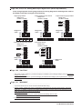
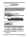
User’s
Manual
DR232/DR242
Hybrid Recorder
(Expandable Type)
Notice of Alterations
Please note the following(underlined) alterations to the IMDR232-01E.
Page 3 “Main Unit DR232/DR242”
Model
Suffix Code
··············
······························································
Description
Power Cord
D····················
3-pin inlet w/UL, CSA cable* (Part No. A1074WD)
F····················
3-pin inlet w/VDE cable* (Part No. A1009WD)
R····················
3-pin inlet w/AS cable* (Part No. A1024WD)
S····················
3-pin inlet w/BS cable* (Part No. A1023WD)
H····················
3-pin inlet w/GB cable* (complies with the CCC)(Part No. A1064WD)
W····················
3-pin inlet with screw conversion terminal**
······························································
Page 3 “Subunit DS400/DS600”
Model
Suffix Code
··············
······························································
Description
Power Cord
D····················
3-pin inlet w/UL, CSA cable (Part No. A1074WD)
F····················
3-pin inlet w/VDE cable (Part No. A1009WD)
R····················
3-pin inlet w/AS cable (Part No. A1024WD)
S····················
3-pin inlet w/BS cable (Part No. A1023WD)
H····················
3-pin inlet w/GB cable (complies with the CCC)(Part No. A1064WD)
W····················
3-pin inlet with screw conversion terminal (when power supply suffix code is -1)
······························································
Page 5 “Standard Accessories”
1. One of these power cord types is supplied according
to the instrument's suffix code
D
F
R
S
H
The “7. Clamp filter (Part No. A1197MN)” is not supplied.
Page 7 “Safety Precautions”
The following caution has been added.
CAUTION
This instrument is a Class A product. Operation of this instrument in a residential area may cause
radio interference, in which case the user is required to take appropriate measures to correct the
interference.
Page 2-14 “HOLD/NON-HOLD Setting”
You can select whether to hold the operating status of operated internal switches or alarm output
relays. This setting applies to both the internal switches and the alarm output relays.
However, non-hold always applies to relays for which the reflash alarm is set, regardless of the hold/non-hold
setting.
Yokogawa Electric Corporation
IM DR232-01E-9A 1/5
for IM DR232-01E 9th Edition
Page 2-18 “External In/Output Function (alarm module or DI/DO module is required)”
• Fail Output *
One transfer contact in the DI/DO module is used for fail output. This relay will change to the de-energized
status when a failure of the recorder occurs.
* Fails are output when CPU abnormalities, power failures, or other problems occur. They are not output as a result of
errors in recognizing I/O output modules or subunits, or of overranges or errors in measured data.
Page 3-5 “Installation Method”
• Direct panel mounting
Attach the unit to the 2 mm-thick metal plate using the 6 screws included (length : 16 mm) according to the
figure below.
Page 3-20 “WARNING”
············································································································
• When 30 VAC or 60 VDC and more is applied to the output terminal of the alarm output module or the output
terminal of the DI/DO module, use double-insulated wires (withstand voltage performance: more than 2300
VAC) for those wires which apply 30 VAC or 60 VDC and more. All other wires can be basic-insulated
(withstand voltage performance: more than 1390 VAC).··············································
• To prevent fire, use signal wires having a temperature rating of 75°C or more.
Page 3-20 “CAUTION”
············································································································
• The overvoltage category of each input module is CAT ll (IEC61010-1, CSA22.2 No.61010-1).
• The measurement category of each input module is CAT ll (IEC61010-1, CSA22.2 No.61010-1).
• When connecting to a clamp terminal, use a signal conductor with the following cross-sectional width:
············································································································
IM DR232-01E-9A 2/5
for IM DR232-01E 9th Edition
Page 3-23, 3-24, 3-25 “Wiring Strain Input Signal Lines (Strain Input Module)”
In the wiring diagrams of each gauge method, the wiring diagram for the bridge box used for
the DU500-14 has been changed to the following:
• Single-gauge method
• Single-gauge three-wire method
Bridge head
(701955 or 701956)
Bridge head
(701955 or 701956)
1
2
3
4
5
6
7
8
Rg
Bridge head
switch
ON
Bridge head
switch
ON
Rg1
Rg2
Bridge head
switch
ON
OFF
OFF
SW
Bridge head
(701955 or 701956)
1
2
3
4
5
6
7
8
Rg
SW
1 2 3 4 5
SW1 SW2 SW3 SW4 SW5
ON ON ON ON OFF
• Adjacent-side two-gauge method
1
2
3
4
5
6
7
8
OFF
1 2 3 4 5
SW
SW1 SW2 SW3 SW4 SW5
OFF ON ON ON OFF
1 2 3 4 5
SW1 SW2 SW3 SW4 SW5
OFF ON ON ON OFF
• Opposed-side two-gauge method
Bridge head
(701955 or 701956)
Rg1
Rg2
Bridge head
switch
ON
Bridge head
(701955 or 701956)
1
2
3
4
5
6
7
8
Rg1
Rg4
Rg2
Rg3
1
2
3
4
5
6
7
8
Bridge head
switch
ON
OFF
OFF
SW
• Four-gauge method
1 2 3 4 5
SW1 SW2 SW3 SW4 SW5
ON OFF ON ON OFF
SW
1 2 3 4 5
SW1 SW2 SW3 SW4 SW5
OFF OFF OFF ON OFF
Page 3-26 “CAUTION”
············································································································
• The power monitor module is a product belonging to Installation (Over-voltage) Category CAT II (IEC61010-1,
CSA22.2 No.61010-1).
• The power monitor module is a product belonging to Measurement Category CAT II (IEC61010-1, CSA22.2
No.61010-1).
Page 3-31 “WARNING”
············································································································
• To prevent electric shock, do not touch the terminals after wiring.
• Furnish a switch (double-pole type) to separate the instrument from the main power supply in the power
supply line. In addition, make sure to indicate that the switch is a power control for the instrument on the
switch and the ON/OFF positions of the switch.
Switch Specifications
Steady-state current rating: 3 A or more, inrush current rating: 90 A or more
Use a switch complied with IEC60947-1, -3.
• Do not add a switch or fuse to the ground line.
IM DR232-01E-9A 3/5
for IM DR232-01E 9th Edition
Page 4-13 “Clock Display”
The date and time can be displayed on sub-display 2.
According to the set time in 3.10, “Setting the Date and Time” (see page 3-35), the current date and
time is displayed.
The display shows the month, day, year and hour, minute, second in this sequence.
Page 13-5 “Error Codes”
The following error codes have been added to the list.
Error Codes
012
Error
None of the channels specified in execution of
initial balance were strain input channels.
Attempted “REP RECALL START” without hourly,
daily, or monthly report data.
Set to contiguous channels on the power monitor
module.
Entered a wiring method for which there is no
setting for the power monitor module.
Attempted to change ranges or time while report
was starting.
Media write error
Attempted to start computation or execute a
procedure during saving of settings to a medium
or while reading from a medium.
Media drive error
013
032
047
107
131
137
138
146
An initial balancing error occurred during
calibration.
Corrective Action
Enter a correct channel.
Enter a correct channel.
Enter the correct wiring method.
Do not make changes.
Exchange the medium.
Start the procedure or computation after
completion of the media operation.
Exchange the medium. If the error occurs again
after exchanging the medium, servicing is
required.
Check the wiring and try calibration again.
Page 13-8 “calibrations”
For “Strain measurement” under “Connection,” the wiring diagram for the bridge box used
for the DU500-14 has been changed to the following:
Bridge head
(701955 or 701956)
1
2
3
4
5
6
7
8
R2
R1
R4
R3
Connect CH2 only
Switch the
bridge head
ON
OFF
SW
1 2 3 4 5
SW1 SW2 SW3 SW4 SW5
OFF OFF OFF ON OFF
Page 14-3 “Standard Computation Functions”
Scaling
Measurement accuracy for scaling: measurement accuracy for scaling (digits) = measurement
accuracy (digits) × scaling span (digits) / measurement span (digits) + 2 digits. Numbers below
the decimal point are rounded up.
±(((0.05/100) × 5000) + 2) × (2000/4000) + 2 = ±4.25
Measurement accuracy = ±5 digits = ±0.005 V
IM DR232-01E-9A 4/5
for IM DR232-01E 9th Edition
Page 14-8 “Normal Operation Conditions”
Installation category based on IEC61010-1, CSA22.2 No.61010-1
II*1
Pollution degree based on IEC61010-1, CSA22.2 No.61010-1
2*2
Warm-up time
At least 30 minutes after power switch-on.
*1 Describes a number which defines a transient overvoltage condition. It implies the regulation for impulse
withstand voltage. “II” applies to electrical equipment which is supplied from fixed installations like distribution
boards.
*2 Describes the degree to which a solid, liquid, or gas which deteriorates dielectric strength or surface
resistivity is adhering. “2” applies to normal indoor atmosphere. Normally, only non-conductive pollution
occurs.
Page 14-9 “EMC Eonformity Standards”
Please refer to these specifications instead of the one printed in the user's manual.
Safety and EMC Standards
CSA
UL
C-Tick
KC marking
CSA22.2 No.61010-1, installation category II, pollution degree 2
UL61010-1 (CSA NRTL/C)
EN55011 compliance, Class A, Group 1
Electromagnetic wave interference prevention standard, electromagnetic wave protection standard compliance
Page 14-12 “Measurement range, accuracy and resolution”
Input
DC Voltage
Type
20mV
60mV
200mV
2V
:
Measurement (digital display)
Measurement range
Measurement accuracy
(0.05% of rdg + 5digits)
–20.000 to 20.000mV
(0.05% of rdg + 2digits)
–60.00 to 60.00mV
(0.05% of rdg + 2digits)
–200.00 to 200.00mV
(0.05% of rdg + 2digits)
–2.0000 to 2.0000V
:
:
Maximum
resolution
1µV
10µV
10µV
100µV
:
Page 14-15, 14-19, 14-21, 14-23, 14-25 “Specifications of Module”
Installation Category (Overvoltage Category)
CAT II (IEC61010-1, CSA22.2 No.61010-1)
Measurement Category
CAT II (IEC61010-1, CSA22.2 No.61010-1)
Page 14-20 “Measuring Ranges and Accuracies”
Gauge Method
Single-gauge
Two-gauge
Four-gauge
Measurement Range Type
2000µε
20000µε
200000µε
1000µε
10000µε
100000µε
500µε
5000µε
50000µε
Rated Measurement Range
-2000 to 2000µε
-20000 to 20000µε
-200000 to 200000µε
-1000 to 1000µε
-10000 to 10000µε
-100000 to 100000µε
-500 to 500µε
-5000 to 5000µε
-50000 to 50000µε
Accuracy
0.5% of Range
0.3% of Range
0.3% of Range
0.5% of Range
0.3% of Range
0.3% of Range
0.5% of Range
0.3% of Range
0.3% of Range
Resolution
0.1µε
1µε
10µε
0.1µε
1µε
10µε
0.1µε
1µε
10µε
Page 14-21 “Specifications of Strain Input Module”
Accesorry
Bridge head: 701955, 701956
IM DR232-01E-9A 5/5
for IM DR232-01E 9th Edition