1
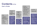
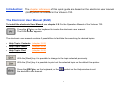
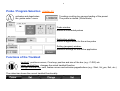
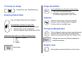
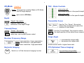
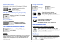
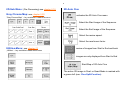
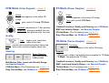
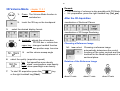
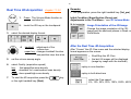
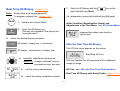
GE Medical Systems
Kretz Ultrasound
User’s Guide
Direction 105847
Revision 0
VOLUSON® 730
0366
Copyright© 2002 by GE Medical Systems - Kretz Ultrasound
Revision History
Reason for Change
REV
DATE
REASON FOR CHANGE
Rev.0
April 30, 2002
Initial Release
List of effective Pages
PAGE NUMBER
REV #
Cover
0
Revision History
0
Contents
0
Page 1 - 18
0
PAGE NUMBER
REV #
of the
User’s Guide
·
·
·
·
Basic
Measurements
12
Calculation
Measurements
·
OB Calculations
·
GYN Calculations
·
Cardio
·
Real Time 4D
Biopsy
13
VCI (Volume
Contrast 14
Imaging)
·
Live 3D Mode
·
Printing
Calculations
·
Recording
Vascular
·
Saving
Calculations
·
Report
17
·
Spectral
Doppler
·
Real-Time
Trace
4D Cine
16
·
·
Real Time
4D-Mode
8
·
CFM-Mode
·
PD-Mode
·
TD-Mode
·
15
·
·
·
2D-Mode
·
Depth, Power,
Frequency,
Harmonic Imaging,
TGC, Focus, OTI,
Image Angle
4
·
β-View, FFC, CRI
·
Trapezoid-Mode
·
Image Orientation
·
Multi-format
·
HR-/ Pan-Zoom
5
9
·
Introduction
·
Electronic User
Manual (EUM)
·
Probe / Program
Selection
·
Functions of the
Trackball
1
2
·
Gray Chroma Map
·
Freeze /Run
·
Utilities- Menu
·
3D Volume
10
Mode
·
2D Auto Cine
Entering Patient
Data
·
Cine-Mode
·
Image Annotation
3D Rotation
11
Cine
·
Spectral Doppleror M-Cineloop
·
Indicator
·
Pictograms
Tool Menu
·
·
Graphic clear
M-Mode
6
7
3
Introduction: The chapter references of this quick guide are based on the electronic user manual
(EUM) which is installed in the Voluson 730.
The Electronic User Manual (EUM)
To install the electronic User Manual see chapter 3.6.1 in the Operation Manual of the Voluson 730.
Press the [F1] key on the keyboard to invoke the electronic user manual.
The EUM-screen appears.
The electronic user manual contains 3 possibilities to facilitate the searching for desired topics:
·
Help Topic: Contents (chapter 3.6.3)
·
Help Topic: Index
(chapter 3.6.4)
·
Help Topic: Find
(chapter 3.6.5)
With the [Back] key it is possible to change to the topic selected previously.
With the [Print] key it is possible to print out the selected topic on the default line printer.
Press the [ESC] key on the keyboard, or the
the electronic user manual.
symbol on the Help-window to exit
1
2
Probe / Program Selection chapter 4.5
activates and deactivates
the „probe select“ menu
Touching a setting key causes loading of the preset.
The probe is started. (Write-Mode)
Probe window:
shows all connected probes
Application window:
shows all applications for the active probe
Setting (program) window:
shows all settings for the active application
Functions of the Trackball
trackball: positions cursors, Cine-loop, position and size of the box (e.g.: C-ROI) etc.
upper trackball key: changes the actual trackball function
left/right trackball key: sets, fixates cursors and activates pages/buttons (e.g.: Start, Vol_pre, Exit, etc.)
The status bar shows the current trackball functionality.
To freeze an Image
Image Annotation
Freeze/Run resp. Read/Write-key
DOC
Entering Patient Data
two possibilities to write text on the screen:
1. input with the keyboard keys
2. annotation with predefined words
for different applications (Auto Text)
Indicator
Input of Patient Data with the keyboard
Position the indicator using the trackball.
Direction (360° rotation) with the digipot.
Fixation with the trackball keys.
3 possibilities to select an input field:
1.
2.
3.
with the trackball and the trackball keys
with the keys on the touchpanel
with the keyboard keys [Enter] and [Tab]
Pictogram (Bodymarks)
The touchpanel shows previous used bodymark.
Fixation with the right resp. left trackball key.
Adjust the scan plan line with the “Angle” knob.
Additional input fields for 4 different applications:
1.
2.
3.
4.
General = default
OB
GYN
Cardio
changes between the different applicationrelated bodymarks
Graphic clear
Start Exam
clear graphics and annotations on the screen
3
4
2D-Mode chapter 5
2D
TGC - Slider Controls
Press: changes from another Mode to 2D-Mode
and to Single display!
slide to the left:
decreases the gain in the specific depth
Turn: gain control (2D-Gain)
slide to the right:
increases the gain in the specific depth
Depth
“Depth” -flip control:
stepwise reduction resp.
extension of the depth range
Transmitter Focus
Use the “Foc. Zones“ -flip control
(below the touchpanel) to select the
number of focal zones.
Transmit Power
“Power” -flip control:
flipping up-/down adjusts
more resp. less transmit power output
Receiver Frequency Range
penet: high resolution / lower penetration
norm: mid resolution / mid penetration
resol: lower resolution / high penetration
Harmonic Imaging
HAR
Switch on / off the Harmonic Imaging function
Use the “Focus Depth“ -flip control to select
the depth position of the actual focus zone(s)
Image Angle
® increases the image width
¬ decreases the image width
smaller sector width = higher frame rate
OTI (Optimized Tissue Imaging)
four positions are possible:
adipose, solid, cystic and normal
β-View (Beta View)
Image Orientation
adjustment of the O-axis of 3D probes in 2D-Mode
left /right
Turn: changes the position of the
acoustic block
Press: back to 0° position
up/down
B-Dual
Press this keys to change
from Single or Quad to “B-Dual”.
FFC (Focus and Frequency Composite)
next position (Dual): 1>2>1 and so on.
switch on /off the [FFC] function
in 2D-Mode
B-Quad
Press this key to change from
Single or Dual to “B-Quad”.
Trapezoid-Mode
next position (Quad): 3>4>1 and so on.
selection of Linear- or
Trapezoid-Mode display
High Resolution Zoom
CRI (Compound Resolution Imaging)
magnification of the 2D-image in Write-Mode:
upper trackball key changes position / size
Switch on / off the [CRI] function
in 2D-Mode
Press this key again to activate the “HR-Zoom”
and to exit the Zoom function.
Remark:
Pan-Zoom
The keys for the functions Focal Zones, OTI, β-View, 2DAngle, Frequency, FFC, CRI and Trapezoid-Mode only
appear on the touchpanel if they are available for the
selected probe.
magnification of the 2D-image in Read- and Write-Mode:
Zoom-digipot: (below the touchpanel)
Press: activates the Factor 1.0
5
6
2D-Sub Menu: (Pre-Processing) see chapter 5.19
Gray Chroma Map: see chapter 5.20
“Gray Chroma Map” – key available in each Sub-menu
2D Auto Cine
activates the 2D Auto Cine menu
Select the Start Image of the Sequence.
Select the End Image of the Sequence.
Select the review speed.
Select the read zoom factor.
Utilities-Menu: see chapter 12
review of images from Start to End and back
„Utilities“ – key available in each Main-menu
images are only displayed from Start to End
Start/Stop of 2D Auto Cine
The active 2D-image in Dual- or Quad-Mode is marked with
a green dot! (see: Cine-Split-Function)
M-Mode chapter 6
Cine-Split-Function
X
Press the format keys to change to the next
(part of) frozen 2D-image sequence.
Press: The M-Cursor appears in the active
2D-image.
Turn:
M
gain control (M-Gain)
The trackball keys activate the M-Mode.
Cine-Mode
Move the trackball to display the stored
2D-images one by one.
Sweep Speed
four different sweep speeds:
2.0 ; 3.5 ; 6.0 ; 10.0 cm/s
Spectral Doppler- or M-Cineloop
Invert (up/down)
upper trackball key:
(only possible with endo-vaginal probes)
changes between the 2D-Cine and the
M- or D-Loop
Format see M-Sub menu
chapter 6.3
trackball: to recall the stored sequence
The active Cine is displayed on the monitor:
2D/M-Image or 2D/M-Image
2D/D-Image or 2D/D-Image
Depth, Frequency and TGC-Slider Controls:
see 2D-Mode
M-Sub Menu: (Pre-Processing) see chapter 6.3
Gray Chroma Map: see 2D-Mode or chapter 5.20
7
8
Spectral Doppler chapter 7
Pulsed Wave Doppler: chapter 7.1
Z
PW
Press:
The PW-Cursor appears in the active 2D-image.
Turn:
gain control (PW-/ resp. CW-Gain)
Continuous Wave Doppler: chapter 7.2
CW
Press:
The CW-Cursor appears in the active 2D-image.
trackball: Doppler-Cursor- resp. gate-position
upper key: changes the trackball function
left key: either Doppler- or 2D-image active
right key: Doppler- and 2D-Mode active
Baseline
shifting up and down in 8 steps
(possible in Read- and Write-Mode)
Velocity Range
higher Vel. range = higher PRF
maximum is exceed: HPRF is switched on
Angle Correction
adjustment in Write- and Read-Mode
Press: the angle correction switches
from + 60° to 0° and to – 60°
CW-Doppler: The angle correction line is at the same
time the depth marker for the focus.
Wall-Motion Filter
Settings: low1, low.2, mid1, mid2,
high1, high2 and max.
Real-Time Trace
Display: envelope curve simultaneously
with the Doppler spectrum
Switch on / off the Real-Time Trace
Sweep Speed, Invert, Format and Cineloop:
see M-Mode
PW-Sub Menu: (Pre-Processing) see chapter 7.1.3
CW-Sub Menu: (Pre-Processing) see chapter 7.2.3
Gray Chroma Map: see 2D-Mode or chapter 5.20
CFM-Mode (Color Doppler) chapter 8
PD-Mode (Power Doppler) chapter 9
Y
Press:
The C-box appears in the active 2Dimage.
C
Press:
PD-box appears in the active 2D-image
Turn: gain control (PD-Gain)
Turn: gain control (C-/ resp. TD-Gain)
trackball: adjustment of C-box position
upper key: changes trackball function
box-position resp. box-size
Quality
high:
PD
Trackball functions, Quality and Steering: see CFM-Mode
WMF and Velocity Range: see Spectral Doppler
PD-Sub Menu: (Pre-Processing) see chapter 9.3
Gray-/Chroma Map: see 2D-Mode or chapter 5.20
higher color resolution/
lower frame rate
norm: normal color resolution/medium frame rate
lower color resolution/higher frame rate
low:
TD-Mode (Tissue Doppler) chapter 10
Steering
Remark:
Beam Steering:
only possible with
linear probes
Wall-Motion Filter, Invert and Velocity Range:
see Spectral Doppler
CFM-Sub Menu: (Pre-Processing) see chapter 8.3
Gray Chroma Map: see 2D-Mode or chapter 5.20
Touching:
TD-box appears in the active 2D-image
[TD] key only visible if selected probe is capable for TD-Mode
· “C-Mode” key adjusts the TD-Gain
·
Trackball functions, Quality and Steering: see CFM-Mode
WMF, Invert and Velocity Range: see Spectral Doppler
TD-Sub Menu: (Pre-Processing) see chapter 10.3
Gray-/Chroma Map: see 2D-Mode or chapter 5.20
9
10
3D Volume-Mode chapter 11.3.1
3D/4D
1.
2.
3.
Press: The Volume-Mode function is
switched on.
touch the 3D-key on the touchpanel
Remark:
· The obtaining of volumes is also possible with PD-Mode.
· Vol.-preparation: press the right trackball key (Vol_pre)
After the 3D-Aquisition
visualization of Sectional Planes
select the desired display format:
visualization of 3D Image Rendering
4. trackball: adjusts the volume-box
PD ROI-box = volume-box
Choosing a Reference Image
upper key: changes trackball function
box-position resp. box-size
5.
6.
set the volume sweep angle
select the quality (acquisition speed)
low: fast speed/low scan density
mid: stand. scan/medium scan density
high2: slow speed/high scan density
7.
Choosing a reference image
automatically determines the control
functions of the rotary controls and the
trackball for the liberal adjustment of a
sectional plane.
To start 3D acquisition press the
or the right trackball key (Start).
key
Rotation of the Reference Image
X
Y
Z
M
PD
PW
about X-axis
about Y-axis
about Z-axis
Translation of the Reference Image
Tool Menu from chapter 11.3.1.4.13
key in the “3D-Image Rendering” menu
The tool menu appears on the touchpanel.
C
Adjustments in the Tool Menu:
parallel shifting
along X- and Y-axis
Initial Condition
resets the rotations and translations of a
volume section to the initial (start) position
1.
select the desired Render-Direction
2.
select image type and render algorithm:
Surface Modes: (e.g. Surface Smooth)
Transparent Modes: (e.g. X-Ray-Mode)
Magnification (Zoom)
All sectional images A, B and C
and the 3D image will be magnified
resp. reduced.
3D Rotation Cine
to mix two Render-Modes
3.
Gray Chroma Map:
see 2D-Mode or chapter 11.3.1.4.13.7
4.
“MagiCut” see: chapter 11.3.1.4.13.6.1
Use the digipots to rotate the 3D-image.
key in the “3D Image Rendering” menu
5.
select between: New Cine Sequence
Start/Stop calculated Sequence
Operation: see chapter 11.3.1.4.12
(the green line symbolizes the view direction)
6.
11
Threshold controls
TH.high and TH.low (reject) are only
possible in Surface Mode
small number = low transparency
higher number = increases transparency
12
Real Time 4D-Acquisition chapter 11.3.2
3D/4D
3.
1.
Press: The Volume-Mode function is
switched on.
2.
touch the 4D-key on the touchpanel
trackball:
adjustment of the
volume-box
upper key: changes trackball function
box-position resp. box-size
5.
set the volume sweep angle
6.
select Quality (acquisition speed)
To start the 4D acquisition press the
or the right trackball key (Start).
Image Orientation of the 4D-Image
After the Real Time 4D-Acquisition
After “Freeze” the 4D Cine menu and the selected display
format appears on the screen.
·
·
fast speed/low scan density
low:
mid: standard Vol. scan/medium scan density
high2: slow speed/high scan density
7.
Initial Condition, Magnification (Zoom) and
Adjustments in the Tool Menu: see 3D Volume-Mode
Change the image orientation of the 3Dimage and the sectional planes in Read- or
Write-Mode.
select the desired display format:
4.
Remarks:
· Vol.-preparation: press the right trackball key (Vol_pre)
key
Start/Stop the 4D Cine
the last 64 images will be displayed
(image by image with the trackball)
replay in one direction
replay in both directions
select the Cine speed
6%, 12%, 25%, 50%, 100%, 200%, 400%
7.
Real Time 4D Biopsy chapter 11.4
Note:
Biopsy lines must be programmed!
To program a biopsy line: chapter 19.1
3D/4D
3.
1.
activate the Volume-Mode
2.
touch the 4D Biopsy key
(This key only appears if the biopsy line
is programmed.)
Start the 4D Biopsy with the
right trackball key (Start).
key or the
Vol.-preparation: press right trackball key (Vol_pre)
Initial Condition, Magnification (Zoom) and
Adjustments in the Tool Menu: see 3D Volume-Mode
changes the render-view direction
(green line)
select the desired biopsy procedure:
2D-image + biopsy line + volume-box
After the Real Time 4D Biopsy
The 4D Cine menu appears on the screen.
2D image + volume-box (no biopsy line)
Start/Stop 4D Cine
4.
trackball: adjusts the volume-box
With the trackball the 4D sequence will be displayed
image by image.
upper key: changes trackball function
box-position resp. box-size
5.
set the volume sweep angle
4D Cine: see After the Real Time 4D-Acquisition
Real Time 4D Biopsy with Rectal Probe: chapter 11.4.4
6.
select the quality (acquisition speed)
13
14
VCI (Volume Contrast Imaging) chapter 11.5
[VCI] improves the contrast resolution and therefore
facilitates finding of diffuse lesions in organs.
7.
Start the VCI-4D acquisition with the
or the right trackball key (Start).
key
Vol.-preparation: press right trackball key (Vol_pre)
3D/4D
1.
activate the Volume-Mode
Initial Condition, Magnification (Zoom) and
Adjustments in the Tool Menu: see 3D Volume-Mode
2.
3.
touch the VCI key
select the desired display format:
changes the render-view direction
(green line)
Real-time 4D Display: A ROI + 4D Image
After the Volume Contrast Imaging
Real time single 4D Image Rendering
4. trackball: adjusts the volume-box
upper key: changes trackball function
box-position resp. box-size
5.
The 4D Cine menu appears on the screen.
Start/Stop 4D Cine
With the trackball the 4D sequence will be displayed
image by image.
set the Slice Thickness
4D Cine: see After the Real Time 4D-Acquisition
6.
select the quality (acquisition speed)
Live 3D Acquisition chapter 11.3.3
3D/4D
1.
Printing
activate the Volume-Mode
(Live 3D-probe must be connected and
selected!)
(default) chapter 16.1
B
A
Black/White-Printer
2.
3.
touch the Live 3D key
Color-Printer
Recording chapter 16.2
select the desired display format:
Operation of the video recorder
Saving chapter 16.3
4.
trackball: adjusts the Volume-box
1. To store 2D-images, 2D-Sequences,
3D-Volumes and 4D-Sequences either in
Sonoview, or to send to a DICOM server.
2. Stores AVI-Files on MOD- or CD/RW-Disk.
upper key: changes trackball function
box-position resp. box-size
5.
set the volume sweep angle
6.
select the quality (acquisition speed)
7.
acquisition start and stop: press the
review of stored images and sequences
Sonoview: see chapter 15
key.
Report
Initial Condition, Magnification (Zoom) and
Adjustments in the Tool Menu: see 3D Volume-Mode
·
·
·
·
Image Orientation and Cine-Mode:
see Real Time 4D-Acquisition
15
OB report
GYN report
Cardiac report
Vascular report
chapter 14.2
chapter 14.5
chapter 14.7
chapter 14.10
16
Basic Measurements chapter 13
mm
·
·
·
Note:
trackball: positioning of measuring marks
lt./rt. key: sets the measuring marks
upper key: to change measuring marks
erases measurement result
Calculation Measurements chapter 14
Remark:
trackball: positioning of measuring marks
lt./rt. key: sets the measuring marks
upper key: to change measuring marks
Distance measurements
Area measurements
Volume measurements
Operation:
Calc
Operation:
1.
2.
3.
4.
OB calculations
GYN calculations
Cardiac calculations
Vascular calculations
Confirm that the patient information is
correct and the probe and corresponding
application are selected properly !
To increase the workflow speed (for details see: chapter
18.3.1) also the
key can be used to confirm the
last measuring mark of the currently performed measurement.
Additional functions:
to cancel the measurement of the selected item
to delete the results of the last measured item
to delete all measurements of selected group
from the monitor as well as from the report
to exit the Calculation Measurement program
OB Calculations chapter 14.1
Fetal Biometry:
Fetal Cranium:
Fetal Long Bones:
Fetal Doppler:
AC, BPD, FL, HC, CRL, etc.
Cerebellum, OOD, IOD, etc.
Humerus, Ulna, Tibia, etc.
Umb. Artery, Fetal Aorta, etc.
Cardiac Calculations chapter 14.6
·
B-Mode:
·
M-Mode: LV, MV; Ao/LA; HR
·
D-Mode: MV, R-R Interval, AoV, TV, PV,
LVOT- / RVOT-Doppler, PAP,
Pulmonic Veins, HR
Operation: see Calculation Measurements
·
C-Mode: PISA-Radius and PISA-Alias Velocity
The results are included in the OB report.
Operation: see Calculation Measurements
·
·
·
·
e.g.
e.g.
e.g.
e.g.
AFI (Amniotic Fluid Index), NT (Nuchal Translucency)
Simpson, Vol A/L, 2D-Measurements,
LV-Mass, LVOT- / RVOT-Diameter
The results are included in the Cardiac report.
GYN Calculations chapter 14.4
·
·
B-Mode:
Uterus, Lt./Rt. fetal Kidney, Lt./Rt. Ovary,
Lt./Rt. Follicles
D-Mode: Lt./Rt. Ovarian Artery, Heart Rate
Vascular Calculations chapter 14.9
■ Lt./Rt. ICA, Lt./Rt. CCA, Lt./Rt. ECA and Peripherals
Operation: see Calculation Measurements
·
B-Mode: Stenosis (%StA, %StD), Vessel Area,
Vessel Distance
The results are included in the GYN report.
·
M-Mode: Heart Rate
Operation: see Calculation Measurements
The results are included in the Vascular report.
17
18