1
PinPoint-E EV-DO
User Guide
AirLink Communications, Inc.
version 2.23
May 2006
Information in this document is subject to change without notice
©Copyright AirLink Communications, Inc., 1993-2006. All rights reserved.
WARNING
The antenna(s) used for this transmitter must be installed to provide a separation distance of at
least 20 cm from all persons and must not be co-located or operating in conjunction with any other
antenna or transmitter.
Important Notice
Because of the nature of wireless communications, transmission and reception of data can never
be guaranteed. Data may be delayed, corrupted (i.e., have errors) or be totally lost. Although significant delays or losses of data are rare when wireless devices such as the AirLink Communications modem are used in a normal manner with a well-constructed network, the AirLink modem
should not be used in situations where failure to transmit or receive data could result in damage of
any kind to the user or any other party, including but not limited to personal injury, death, or loss
of property. AirLink Communications, Inc., accepts no responsibility for damages of any kind
resulting from delays or errors in data transmitted or received using the AirLink Communications
modem, or for failure of the AirLink Communications modem to transmit or receive such data.
Safety and Hazards
Do not operate the AirLink Communications modem in areas where blasting is in progress, where
explosive atmospheres may be present, near medical equipment, near life support equipment, or
any equipment which may be susceptible to any form of radio interference. In such areas, the AirLink Communications modem MUST BE POWERED OFF. The AirLink Communications
modem can transmit signals that could interfere with this equipment. Do not operate the AirLink
Communications modem in any aircraft, whether the aircraft is on the ground or in flight. In aircraft, the AirLink Communications modem MUST BE POWERED OFF. When operating, the
AirLink Communications modem can transmit signals that could interfere with various on board
systems. The driver or operator of any vehicle should not operate the AirLink Communications
modem while in control of a vehicle. Doing so will detract from the driver or operator's control
and operation of that vehicle. In some states and provinces, operating such communications
devices while in control of a vehicle is an offence.
Limitation of Liability
The information in this manual is subject to change without notice and does not represent a commitment on the part of AirLink Communications, Inc. AIRLINK COMMUNICATIONS, INC.
SPECIFICALLY DISCLAIMS LIABILITY FOR ANY AND ALL DIRECT, INDIRECT, SPECIAL, GENERAL, INCIDENTAL, CONSEQUENTIAL, PUNITIVE OR EXEMPLARY DAMAGES INCLUDING, BUT NOT LIMITED TO, LOSS OF PROFITS OR REVENUE OR
ANTICIPATED PROFITS OR REVENUE ARISING OUT OF THE USE OR INABILITY TO
USE ANY AIRLINK COMMUNICATIONS, INC. PRODUCT, EVEN IF AIRLINK COMMUNICATIONS, INC. HAS BEEN ADVISED OF THE POSSIBILITY OF SUCH DAMAGES OR
THEY ARE FORESEEABLE OR FOR CLAIMS BY ANY THIRD PARTY.
ii
PinPoint-E EV-DO User Guide for Verizon, version 2.23
Contents
CHAPTER 1
Introduction to PinPoint-E EV-DO . . . . . . . . . . . . . . . . . . . . . . . 1
EV-DO Overview
............................................. 2
Establishing a Internet Connection
............................... 2
Using EV-DO to Communicate with Your Equipment
Common Uses for the PinPoint-E
CHAPTER 2
Activation of the PinPoint-E EV-DO. . . . . . . . . . . . . . . . . . . . . . 5
Connecting the PinPoint-E to your computer
Quick Start Guide and Setup Wizard
PinPoint-E Indicator Lights
....................... 5
.............................. 5
Activating the PinPoint-E using AT Commands
CHAPTER 3
................ 3
................................ 4
..................... 7
..................................... 7
Utilities for the PinPoint-E . . . . . . . . . . . . . . . . . . . . . . . . . . . . . 9
AirLink Configuration Executive (ACE)
. . . . . . . . . . . . . . . . . . . . . . . . . . 10
Wireless ACE 3G . . . . . . . . . . . . . . . . . . . . . . . . . . . . . . . . . . . . . . . . . . . . . . . . . 10
AceNet . . . . . . . . . . . . . . . . . . . . . . . . . . . . . . . . . . . . . . . . . . . . . . . . . . . . . . . . . 11
AceView . . . . . . . . . . . . . . . . . . . . . . . . . . . . . . . . . . . . . . . . . . . . . . . . . . . . . . . . 11
Modem Doctor
. . . . . . . . . . . . . . . . . . . . . . . . . . . . . . . . . . . . . . . . . . . . . . 13
PinPoint-E EV-DO User Guide for Verizon, version 2.23
iii
Contents
AirLink Tracking System (ATS)
CHAPTER 4
. . . . . . . . . . . . . . . . . . . . . . . . . . . . . . . . .13
IP Manager . . . . . . . . . . . . . . . . . . . . . . . . . . . . . . . . . . . . . . . . 15
Fully Qualified Domain Name
Dynamic Name Resolution
. . . . . . . . . . . . . . . . . . . . . . . . . . . . . . . . . .16
. . . . . . . . . . . . . . . . . . . . . . . . . . . . . . . . . . . . .16
Configuring the PinPoint-E for Dynamic IP
Restrictions for Modem Name
DNS: Using Names Instead of IP addresses
Configuring DNS
CHAPTER 5
. . . . . . . . . . . . . . . . . . . . . . . .19
. . . . . . . . . . . . . . . . . . . . . . . . . . . . . . . . . . . . . . . . . . . . . . . . . 19
Keepalive . . . . . . . . . . . . . . . . . . . . . . . . . . . . . . . . . . . . . . . . . . 21
Configuring Keepalive
. . . . . . . . . . . . . . . . . . . . . . . . . . . . . . . . . . . . . . . .21
Data usage using Keepalive
CHAPTER 6
. . . . . . . . . . . . . . . . . . . . . . .17
. . . . . . . . . . . . . . . . . . . . . . . . . . . . . . . . . . . . . . 18
. . . . . . . . . . . . . . . . . . . . . . . . . . . . . . . . . . . . .22
External Inputs and Power Control . . . . . . . . . . . . . . . . . . . . . . 23
Capturing Events via External Inputs
. . . . . . . . . . . . . . . . . . . . . . . . . . . . .23
Setting the DTR and RTS
. . . . . . . . . . . . . . . . . . . . . . . . . . . . . . . . . . . . . . . . . . 23
Connecting to the Serial Port . . . . . . . . . . . . . . . . . . . . . . . . . . . . . . . . . . . . . . . 24
Power Modes
. . . . . . . . . . . . . . . . . . . . . . . . . . . . . . . . . . . . . . . . . . . . . . . .25
Power Effect on Modem State
CHAPTER 7
. . . . . . . . . . . . . . . . . . . . . . . . . . . . . . . . . . . . . . 26
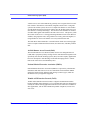
Global Positioning System (GPS) . . . . . . . . . . . . . . . . . . . . . . . 27
GPS Overview
. . . . . . . . . . . . . . . . . . . . . . . . . . . . . . . . . . . . . . . . . . . . . .27
AirLink Remote Access Protocol (RAP) . . . . . . . . . . . . . . . . . . . . . . . . . . . . . . . 28
National Marine Electronics Association (NMEA)
. . . . . . . . . . . . . . . . . . . . . . 28
Trimble ASCII Interface Protocol (TAIP) . . . . . . . . . . . . . . . . . . . . . . . . . . . . . . 28
Real-Time Clock Sync
. . . . . . . . . . . . . . . . . . . . . . . . . . . . . . . . . . . . . . . .29
Configuring the PinPoint-E for GPS
. . . . . . . . . . . . . . . . . . . . . . . . . . . . .29
Over-The-Air (Remote) Host
.......................................
Local Host . . . . . . . . . . . . . . . . . . . . . . . . . . . . . . . . . . . . . . . . . . . . . . . . . . . . . .
Report Types . . . . . . . . . . . . . . . . . . . . . . . . . . . . . . . . . . . . . . . . . . . . . . . . . . . .
Sending Reports Automatically
.....................................
RAP Configuration
29
30
30
31
. . . . . . . . . . . . . . . . . . . . . . . . . . . . . . . . . . . . . . . . . . .32
RAP Reports Over-The-Air (Remote) . . . . . . . . . . . . . . . . . . . . . . . . . . . . . . . . . 32
RAP Reports over a Local Connection (PPP or SLIP)
. . . . . . . . . . . . . . . . . . . 33
RAP Message format . . . . . . . . . . . . . . . . . . . . . . . . . . . . . . . . . . . . . . . . . . . . . . 34
Additional RAP Features
Device ID
iv
. . . . . . . . . . . . . . . . . . . . . . . . . . . . . . . . . . . . . .35
. . . . . . . . . . . . . . . . . . . . . . . . . . . . . . . . . . . . . . . . . . . . . . . . . . . . . . . 35
PinPoint-E EV-DO User Guide for Verizon, version 2.23
Contents
Odometer Data in Reports . . . . . . . . . . . . . . . . . . . . . . . . . . . . . . . . . . . . . . . . . 36
Serial Input Event Reports . . . . . . . . . . . . . . . . . . . . . . . . . . . . . . . . . . . . . . . . . 36
COM1000 Event Reports . . . . . . . . . . . . . . . . . . . . . . . . . . . . . . . . . . . . . . . . . . . 37
Store and Forward for RAP
. . . . . . . . . . . . . . . . . . . . . . . . . . . . . . . . . . . . 38
Store and Forward Reliable Mode . . . . . . . . . . . . . . . . . . . . . . . . . . . . . . . . . . . 39
Sending Reports
. . . . . . . . . . . . . . . . . . . . . . . . . . . . . . . . . . . . . . . . . . . . . . . . . 40
Flush on Event
. . . . . . . . . . . . . . . . . . . . . . . . . . . . . . . . . . . . . . . . . . . . . . . . . . 40
Legacy ATS/RAP
. . . . . . . . . . . . . . . . . . . . . . . . . . . . . . . . . . . . . . . . . . . 41
NMEA Configuration
. . . . . . . . . . . . . . . . . . . . . . . . . . . . . . . . . . . . . . . . . 42
Streaming NMEA Messages over the local port . . . . . . . . . . . . . . . . . . . . . . . . . 42
NMEA Messages Over-The-Air (Remote)
. . . . . . . . . . . . . . . . . . . . . . . . . . . . . 43
NMEA Messages over a Local Connection
. . . . . . . . . . . . . . . . . . . . . . . . . . . . 43
TAIP Emulation Configuration
. . . . . . . . . . . . . . . . . . . . . . . . . . . . . . . . . 44
TAIP Messages Over-the-Air (Remote) . . . . . . . . . . . . . . . . . . . . . . . . . . . . . . . .
TAIP Messages over a Local Connection
.............................
Sending Unsolicited TAIP Messages over a Local Connection
............
Using TAIP Command Emulation
...................................
TAIP ID . . . . . . . . . . . . . . . . . . . . . . . . . . . . . . . . . . . . . . . . . . . . . . . . . . . . . . . .
Supported TAIP Commands . . . . . . . . . . . . . . . . . . . . . . . . . . . . . . . . . . . . . . . .
CHAPTER 8
44
45
46
46
47
47
Simple Network Management Protocol (SNMP) . . . . . . . . . . . 48
SNMP Overview
. . . . . . . . . . . . . . . . . . . . . . . . . . . . . . . . . . . . . . . . . . . . 48
Management Information Base (MIB) . . . . . . . . . . . . . . . . . . . . . . . . . . . . . . . . 49
SNMP Traps . . . . . . . . . . . . . . . . . . . . . . . . . . . . . . . . . . . . . . . . . . . . . . . . . . . . 49
PinPoint-E SNMP Configuration
. . . . . . . . . . . . . . . . . . . . . . . . . . . . . . . 49
Listening Port . . . . . . . . . . . . . . . . . . . . . . . . . . . . . . . . . . . . . . . . . . . . . . . . . . .
Security Level . . . . . . . . . . . . . . . . . . . . . . . . . . . . . . . . . . . . . . . . . . . . . . . . . . .
User Name and Password
.........................................
Trap Destination . . . . . . . . . . . . . . . . . . . . . . . . . . . . . . . . . . . . . . . . . . . . . . . . .
CHAPTER 9
49
50
50
52
Host Modes . . . . . . . . . . . . . . . . . . . . . . . . . . . . . . . . . . . . . . . . 53
AT Mode
. . . . . . . . . . . . . . . . . . . . . . . . . . . . . . . . . . . . . . . . . . . . . . . . . . . 53
PassThru Mode
CHAPTER 10
. . . . . . . . . . . . . . . . . . . . . . . . . . . . . . . . . . . . . . . . . . . . . . 54
Hardware Installation . . . . . . . . . . . . . . . . . . . . . . . . . . . . . . . 56
Connecting the Antennas
Connecting power
. . . . . . . . . . . . . . . . . . . . . . . . . . . . . . . . . . . . . . 56
. . . . . . . . . . . . . . . . . . . . . . . . . . . . . . . . . . . . . . . . . . . 57
Connecting the PinPoint-E to a computer or other device
PinPoint-E EV-DO User Guide for Verizon, version 2.23
. . . . . . . . . . . . 58
v
Contents
APPENDIX 1
Specifications for the PinPoint-E EV-DO . . . . . . . . . . . . . . . . 59
Physical Characteristics: . . . . . . . . . . . . . . . . . . . . . . . . . . . . . . . . . . . . . . . . . .
Data Services & RF Features: EV-DO . . . . . . . . . . . . . . . . . . . . . . . . . . . . . . . .
Environmental: . . . . . . . . . . . . . . . . . . . . . . . . . . . . . . . . . . . . . . . . . . . . . . . . . .
Power Management:
.............................................
Power consumption . . . . . . . . . . . . . . . . . . . . . . . . . . . . . . . . . . . . . . . . . . . . . . .
59
59
60
60
60
APPENDIX 2
Mounting Kit. . . . . . . . . . . . . . . . . . . . . . . . . . . . . . . . . . . . . . . 62
APPENDIX 3
AT Commands. . . . . . . . . . . . . . . . . . . . . . . . . . . . . . . . . . . . . . 64
Using Wireless Ace
. . . . . . . . . . . . . . . . . . . . . . . . . . . . . . . . . . . . . . . . . . .64
Using Telnet Terminal Emulation
Direct Serial Connection
AT Command Tables
. . . . . . . . . . . . . . . . . . . . . . . . . . . . . . . .65
. . . . . . . . . . . . . . . . . . . . . . . . . . . . . . . . . . . . . .67
. . . . . . . . . . . . . . . . . . . . . . . . . . . . . . . . . . . . . . . . .68
Information Commands . . . . . . . . . . . . . . . . . . . . . . . . . . . . . . . . . . . . . . . . . . . .
Information and Status70
Basic Commands . . . . . . . . . . . . . . . . . . . . . . . . . . . . . . . . . . . . . . . . . . . . . . . .
Basic Commands (common AT commands) 72
Activation . . . . . . . . . . . . . . . . . . . . . . . . . . . . . . . . . . . . . . . . . . . . . . . . . . . . . . .
Activation (Provisioning)74
Cellular Network
................................................
Local Network and Host Modes . . . . . . . . . . . . . . . . . . . . . . . . . . . . . . . . . . . . .
Cellular Network (Verizon’s EV-DO)75
Local Network and Host Modes 76
PassThru . . . . . . . . . . . . . . . . . . . . . . . . . . . . . . . . . . . . . . . . . . . . . . . . . . . . . . .
PassThru Mode81
Direct Communication . . . . . . . . . . . . . . . . . . . . . . . . . . . . . . . . . . . . . . . . . . . .
Direct Communication82
Telnet . . . . . . . . . . . . . . . . . . . . . . . . . . . . . . . . . . . . . . . . . . . . . . . . . . . . . . . . . .
Time/Date . . . . . . . . . . . . . . . . . . . . . . . . . . . . . . . . . . . . . . . . . . . . . . . . . . . . . .
Time and Date 84
Telnet84
Friends Mode . . . . . . . . . . . . . . . . . . . . . . . . . . . . . . . . . . . . . . . . . . . . . . . . . . . .
Friends Mode85
DNS . . . . . . . . . . . . . . . . . . . . . . . . . . . . . . . . . . . . . . . . . . . . . . . . . . . . . . . . . . .
Keepalive . . . . . . . . . . . . . . . . . . . . . . . . . . . . . . . . . . . . . . . . . . . . . . . . . . . . . . .
Keepalive86
DNS86
IP Manager . . . . . . . . . . . . . . . . . . . . . . . . . . . . . . . . . . . . . . . . . . . . . . . . . . . . .
IP Manager87
Logging . . . . . . . . . . . . . . . . . . . . . . . . . . . . . . . . . . . . . . . . . . . . . . . . . . . . . . . .
vi
PinPoint-E EV-DO User Guide for Verizon, version 2.23
69
72
74
74
75
81
81
83
84
85
85
86
87
89
Contents
Logging 89
Power
.........................................................
Power Control 89
External Events (Serial Port Inputs)
.................................
External Events 91
GPS . . . . . . . . . . . . . . . . . . . . . . . . . . . . . . . . . . . . . . . . . . . . . . . . . . . . . . . . . . .
GPS92
SNMP (Simple Network Management Protocol) . . . . . . . . . . . . . . . . . . . . . . . . .
SMTP/SMS . . . . . . . . . . . . . . . . . . . . . . . . . . . . . . . . . . . . . . . . . . . . . . . . . . . . . .
SNMP97
SMTP (email) and SMS (messaging)98
Other . . . . . . . . . . . . . . . . . . . . . . . . . . . . . . . . . . . . . . . . . . . . . . . . . . . . . . . . . .
Other Settings 99
89
90
92
96
97
99
APPENDIX 4
Example of the MIB trap . . . . . . . . . . . . . . . . . . . . . . . . . . . 100
APPENDIX 5
GPS Message Format Streams . . . . . . . . . . . . . . . . . . . . . . . .110
NMEA Message Description
. . . . . . . . . . . . . . . . . . . . . . . . . . . . . . . . . . 110
GGA - Global Positioning System Fix Data 110
RMC - Recommended Minimum Navigation Information111
VTG - Vector track and Speed over the Ground 112
TAIP Message Description
. . . . . . . . . . . . . . . . . . . . . . . . . . . . . . . . . . . . 113
Elements of a TAIP message 113
Troubleshooting . . . . . . . . . . . . . . . . . . . . . . . . . . . . . . . . . . . . . . . . . . . . 114
Frequently Asked Questions (FAQ) and Solutions
. . . . . . . . . . . . . . . . . 114
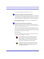
What is RSSI? Why is the RSSI for my PinPoint-E negative? . . . . . . . . . . . . . . 114
What is the Proper RF Coverage for my PinPoint-E? . . . . . . . . . . . . . . . . . . . 115
What Type of Antenna is Best for my PinPoint-E? . . . . . . . . . . . . . . . . . . . . . . 115
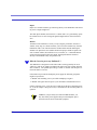
What do I need to power my PinPoint-E ? . . . . . . . . . . . . . . . . . . . . . . . . . . . . 116
Can I use a portable battery to power my PinPoint-E ? . . . . . . . . . . . . . . . . . . 117
I’m Having Problems getting my PinPoint-E registered (activated or provisioned) with
Verizon, what could be the problem? . . . . . . . . . . . . . . . . . . . . . . . . . . . . . . . . . 117
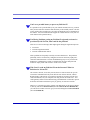
Why Can’t I reach my PinPoint-E from the Internet? What is a Restricted or Private
IP? . . . . . . . . . . . . . . . . . . . . . . . . . . . . . . . . . . . . . . . . . . . . . . . . . . . . . . . . . . . 117
What is the difference between Private Mode and Public Mode? . . . . . . . . . . . 118
How do I set up Private Mode? How do I connect to my PinPoint-E to my router or to
Linux? . . . . . . . . . . . . . . . . . . . . . . . . . . . . . . . . . . . . . . . . . . . . . . . . . . . . . . . . 118
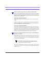
What is the COM1000? . . . . . . . . . . . . . . . . . . . . . . . . . . . . . . . . . . . . . . . . . . . 120
PinPoint-E EV-DO User Guide for Verizon, version 2.23
vii
Contents
How can I update the PRL (Prefered Roaming List) for my EV-DO modem? I have
activated my PinPoint-E but now cannot connect to Verizon, what can be wrong? 120
Can I track vehicle speed with my PinPoint-E? . . . . . . . . . . . . . . . . . . . . . . . . 123
Support web site
. . . . . . . . . . . . . . . . . . . . . . . . . . . . . . . . . . . . . . . . . . . .124
Contacting Technical Support
viii
. . . . . . . . . . . . . . . . . . . . . . . . . . . . . . . . . .124
PinPoint-E EV-DO User Guide for Verizon, version 2.23
CHAPTER 1
Introduction to
PinPoint-E EV-DO
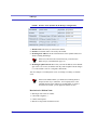
The PinPoint-E's rugged form factor is ideal for industrial and commercial applications that require real-time communications. The PinPoint-E provides cellular data
communications for a variety of applications, such as telemetry, public safety,
SCADA, traffic control, traffic metering, transit arrival systems and more.
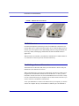
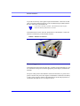
In addition to the primary broadcast and receive antenna port (TNC ANT1), the
PinPoint-E EV-DO is equipped with a secondary receive diversity antenna port
(SMA ANT2). While use of the receive diversity antenna is optional, receive
diversity can provide improved bandwidth throughput and increased coverage, particularly in fringe network areas or mobile environments. Receive diversity also
optimizes performance to help lower power consumption and reduce heat build-up.
Caution: To work correctly, receive diversity requires the two
antennas to be placed at least six inches apart.
Use of receive diversity is optional. Data transmission and reception
will not be adversely affected if it is not used.
PinPoint-E EV-DO User Guide for Verizon, version 2.23
1
Introduction to PinPoint-E EV-DO
FIGURE 1.
PinPoint-E front and back
EV-DO Overview
Evolution Data Optimized (EV-DO) provides a broadband-like cellular data connections that is up to 10 times faster than 1xRTT service. With the high-speed connection, users can experience faster downloading when accessing the Internet and
retrieving e-mails, including large attachments and other bandwidth-intensive
applications.
When EV-DO is not available, your PinPoint-E will fall-back to CDMA/1xRTT for
it’s connection to Verizon to provide continued connectivity.
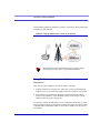
Establishing a Internet Connection
The Internet Service Provider (ISP) from you to the Internet is Verizon with your
PinPoint-E as the connection to Verizon.
When your PinPoint-E is powered on, it automatically searches for cellular service
using EV-DO and establishes a PPP (Point to Point Protocol or “dial” up connection) link to Verizon’s network. As soon as the PinPoint-E receives its IP, it’s ready
to create a network between your computer or device and Verizon’s network so you
can use Verizon to communicate on the Internet.
To use your PinPoint-E to connect to the Internet from your computer, you need to
connect the computer directly to the PinPoint-E’s Ethernet port. The PinPoint-E
2
PinPoint-E EV-DO User Guide for Verizon, version 2.23
Introduction to PinPoint-E EV-DO
features DHCP (enabled by default) so you don’t need to worry about setting up an
IP address on your computer.
FIGURE 2.
Using the PinPoint-E to connect to the Internet
Note: Private network connections are unique for each configu-
ration and not covered as part of the standard installation.
Using EV-DO to Communicate with Your
Equipment
There are two types of addresses in TCP/IP, dynamic and static.
• Dynamic addresses are assigned on a “need to have” basis. Your PinPoint-E
might not always receive the same address each time it connects with Verizon.
• Static addresses are permanently assigned to a particular account and will
always be used whenever your PinPoint-E connects to the Internet. The IP
address will not be given to anyone else.
If you need to contact the PinPoint-E, a device connected to the modem, or a host
system using the modem, you need to have a known IP (such as one which is static)
or domain name (an IP address which is converted by a DNS server into a word
based name).
PinPoint-E EV-DO User Guide for Verizon, version 2.23
3
Introduction to PinPoint-E EV-DO
Most ISPs (cellular included) use dynamic IP addresses rather than static IP
addresses. A dynamic IP address is suitable for many common Internet uses, such
as web browsing, looking up data on another computer system, or other client function (such as data only being sent out or only being received after an initial request).
Note: If you have a dynamic IP address for your PinPoint-E,you
can use a Dynamic DNS service (such as IP Manager coupled
with a Dynamic DNS Server, covered later in this User Guide) to
translate a dynamic IP address to a fully qualified domain name
so you can contact the PinPoint-E as if it had a static IP.
Caution: The IP address given to your PinPoint-E by Verizon
must also be Internet routable if the computer you need to connect to the PinPoint-E is not connected directly to Verizon's IP
network. Please check with Verizon to confirm you IP is scheme
is correct for your application and needs.
Common Uses for the PinPoint-E
The PinPoint-E’s rugged construction and cellular connection make it ideal for use
in remote and/or industrial locations.
Because of its GPS capabilities, the PinPoint-E is ideal for vehicle tracking and
other situations where noting a moving location is as important as connecting to a
network.
4
PinPoint-E EV-DO User Guide for Verizon, version 2.23
CHAPTER 2
Activation of the
PinPoint-E EV-DO
Your PinPoint-E needs specific parameters before it can operate on the EV-DO network. Generally Verizon will provide you with the necessary parameters to get the
PinPoint-E configured.
Connecting the PinPoint-E to your computer
Your PinPoint-E’s Ethernet port can be connected directly to most computers or
devices using a cross-over cable.
Quick Start Guide and Setup Wizard
The preferred way to configure and activate your PinPoint-E is via the AirLink
Setup Wizard for Verizon and EV-DO. The Quick Start Guide will lead you
through the using the Setup Wizard.
• The PinPoint-E Setup Wizard for EV-DO and Verizon is available from the AirLink web site, http://www.airlink.com/support.
• The Quick Start Guide is also available at the AirLink web site.
PinPoint-E EV-DO User Guide for Verizon, version 2.23
5
Activation of the PinPoint-E EV-DO
Note: The web site may have a more recent Setup Wizard and
Quick Start Guide than those included with your PinPoint-E. It
is recommended that you check with the web site for the latest
version before installing your PinPoint-E. You will need to look
for Verizon, EV-DO, and the PinPoint-E. Other Setup Wizards
may not work to connect you to Verizon.
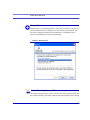
To run the Setup Wizard, you will need the Microsoft .NET framework and
Microsoft Windows 98, Microsoft Windows 2000, Microsoft Windows XP, or later.
1.
Select Start.
2.
Select All Programs.
3.
Select AirLink Communications.
4.
Select Setup Wizard.
5.
Select Setup Wizard.
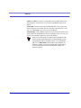
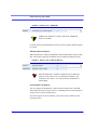
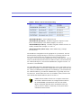
FIGURE 1.
Setup Wizard
The Quick Start Guide specifies the information you need and will lead you
through the steps.
6
PinPoint-E EV-DO User Guide for Verizon, version 2.23
Activation of the PinPoint-E EV-DO
Activating the PinPoint-E using AT Commands
An alternate method to configure and activate your PinPoint-E is by AT commands
(full listing beginning on page 64) sent directly to the modem via a terminal application. This method is recommended only in situations where the Setup Wizard is
not available and/or the configuration for the PinPoint-E is unusual.
Caution: While you can configure your PinPoint-E using Wire-
less ACE (page 10) or AceNet (page 11), it is not recommended
to activate the PinPoint-E using either Wireless ACE or AceNet.
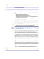
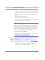
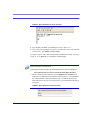
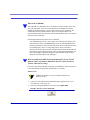
PinPoint-E Indicator Lights
When your PinPoint-E is connected to power and an antenna, there is a specific pattern to the lights to indicate its operation mode.
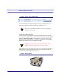
FIGURE 2.
PinPoint-E indicator lights
Tx (transmit) and Rx (receive) - Lights will flash as data is transferred to and
from the PinPoint-E on the remote network.
RSSI - Light shows the strength of the signal and may be nearly solid (strong signal) or
flashing (weaker signal). A slow flash indicates a very weak signal.
Reg - Indicates the PinPoint-E has acquired an IP from Verizon.
Chan - Indicates the modem has acquired a network channel.
Link - Indicate a successful connection to the cellular network.
PinPoint-E EV-DO User Guide for Verizon, version 2.23
7
Activation of the PinPoint-E EV-DO
Srvc - Indicates when the connection is EV-DO. Unlit indicates CDMA.
Pwr - Indicates the power adapter is connected and there is power getting to
the modem.
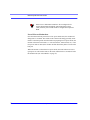
The Reset button performs the same function as unplugging power from the
modem and plugging it back in. Reset will not alter any saved configuration
settings.
8
PinPoint-E EV-DO User Guide for Verizon, version 2.23
CHAPTER 3
Utilities for the PinPoint-E
AirLink offers a suite of utilities to optimize your PinPoint-E’s performance, allowing you to remotely view status and make changes to the configuration as needed.
•
•
•
•
Wireless ACE 3G
AceNet
Modem Doctor
AirLink Tracking System
This section of the PinPoint-E User Guide covers basic information about these
utilities. For additional information on a specific utility, please refer to the user
guide for that utility.
These utilities, except AceNet and AirLink Tracking System (ATS), are free of
charge to those who own AirLink modems. You can download the utilities and
their user guides from the AirLink web site: http://www.airlink.com/support. Contact your dealer or AirLink representative for information on AceNet and ATS.
Note: Wireless ACE 3G, and AceNet require the Microsoft .NET
Framework and Microsoft Windows 98, Windows 2000, Windows XP, or later.
PinPoint-E EV-DO User Guide for Verizon, version 2.23
9
Utilities for the PinPoint-E
You can obtain the Microsoft .Net Framework, Microsoft Internet Explorer, and/or the latest ActiveX updates for Internet
Explorer from Microsoft at: http://www.microsoft.com/.
AirLink Configuration Executive (ACE)
The AirLink Configuration Executive provides a user friendly interaction with
ALEOS, the brains of your PinPoint-E.
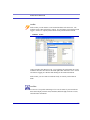
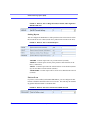
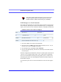
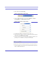
Wireless ACE 3G
Wireless ACE 3G allow you to monitor your PinPoint-E either remotely or locally
with a direct connection to the modem.
Note: Most configuration screen shots in this guide are using
Wireless ACE 3G.
FIGURE 1.
10
Wireless ACE 3G
PinPoint-E EV-DO User Guide for Verizon, version 2.23
Utilities for the PinPoint-E
AceNet
With AceNet you can monitor several AirLink modems at the same time. The
modems can be connected locally or remote. Several features can be displayed and
logged. AceNet is a seperate product which can be purchased from AirLink.
FIGURE 2.
AceNet
Using a template from Wireless ACE, you can change the configuration in several
modems at the same time and can check and update their firmware as well. AceNet
also features logging to a database and charting for the monitored modems.
With AceNet, you can connect to modems locally or remotely with TCP/IP or
SMS.
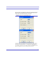
AceView
AceView is a low-profile monitoring tool to view the status of your AirLink PinPoint-E and display network status, IP address, RSSI strength, firmware version,
and other basic information.
PinPoint-E EV-DO User Guide for Verizon, version 2.23
11
Utilities for the PinPoint-E
FIGURE 3.
AceView
You can connect to your PinPoint-E locally or remotely using a known IP address
or a fully qualified domain name. The display is updated periodically as AceView
polls the PinPoint-E at a specified interval. GPS is available only for PinPoint and
PinPoint-E modems.
FIGURE 4.
12
AceView: About Modem
PinPoint-E EV-DO User Guide for Verizon, version 2.23
Utilities for the PinPoint-E
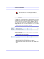
Modem Doctor
Modem Doctor is a troubleshooting utility. This utility will allow you to get a log
file of the PinPoint-E activity which you can then send to AirLink support, erase
the current configuration completely, and temporarily set the PinPoint-E to a
known serial configuration to aid in trouble shooting.
FIGURE 5.
Modem Doctor
AirLink Tracking System (ATS)
The AirLink Tracking System (ATS) is a feature-rich vehicle tracking system that
uses cellular technology to transmit vehicle and location information to a Tracking
PinPoint-E EV-DO User Guide for Verizon, version 2.23
13
Utilities for the PinPoint-E
Control console. ATS also employs the satellite based Global Positioning System
(GPS) to obtain location and velocity information.
ATS is a seperate product which can be purchased from AirLink.
FIGURE 6.
14
AirLink Tracking System
PinPoint-E EV-DO User Guide for Verizon, version 2.23
CHAPTER 4
IP Manager
IP Manager translates a dynamic IP address to a fully qualified domain name so
you can contact your PinPoint-E by name as if it had a static IP.
Since Wireless Service Providers frequently do not offer static IP addresses, IP
Manager is a free service provided by AirLink for your PinPoint-E to translate a
dynamic IP address into a fully qualified domain name so it can be contacted
directly on the Internet.
• Dynamic IP addresses are granted only when a modem or other device is connected and can change each time the modem or device reconnects to the network.
• Static IP addresses are granted the same address every time the modem or
device is connected and are not in use when the associated device is not connected.
A dynamic IP address is suitable for many Internet activities such as web browsing,
looking up data on another computer system, data only being sent out, or data only
being received after an initial request. However, if you need to contact the PinPoint-E directly, a device connected to the modem, or a host system using the PinPoint-E, a dynamic IP won’t give you a reliable address to contact (since it may
have changed since the last time it was assigned).
PinPoint-E EV-DO User Guide for Verizon, version 2.23
15
IP Manager
Fully Qualified Domain Name
A fully qualified domain name (FQDN) generally has several parts.
• Top Level Domain (TLD): The TLD is the ending suffix for a domain name
(.com, .net, .org, etc.)
• Country Code Top Level Domain (ccTLD): This suffix is often used after the
TLD for most countries except the US (.ca, .uk, .au, etc.)
• Domain name: This is the name registered with ICANN (Internet Corporation
for Assigned Names and Numbers) or the registry for a the country of the
ccTLD (i.e. if a domain is part of the .ca TLD, it would be registered with the
Canadian domain registry). It is necessary to have a name registered before it
can be used.
• Sub-domain or server name: A domain name can have many sub-domain or
server names associated with it. Sub-domains need to be registered with the
domain, but do not need to be registered with ICANN or any other registry. It is
the responsibility of a domain to keep track of its own subs.
A URL (Universal Resource Locator) is different from a domain name in that it
also indicates information on the protocol used by a web browser to contact that
address, such as http://www.airlink.com.
• .com is the TLD
• airlink is the domain (usually noted as airlink.com since the domain is specific
to the TLD)
• www is the server registered with AirLink.com
• http:// is the protocol (html or web) used to access the webpage for AirLink
Dynamic Name Resolution
When an IP address is not expected to change, the DNS server can indicate to all
queries that the address can be cached and not looked up for a long period of time.
Dynamic DNS servers, conversely, have a short caching period for the domain
information to prevent other Internet sites or queries from using the old information.
16
PinPoint-E EV-DO User Guide for Verizon, version 2.23
IP Manager
If the PinPoint-E is configured for Dynamic IP, when the PinPoint-E first connects
to the Internet, it sends a IP change notification to IP Manager. IP Manger will
acknowledge the change and update the DNS record. The changed IP address will
then be the address for the PinPoint-E’s configured name.
Once the PinPoint-E’s IP has been updated in IP Manager, it can be contacted via
name. If the IP address is needed, you can use the domain name to determine the IP
address.
Note: The fully qualified domain name of the PinPoint-E will be
a subdomain of the domain used by the IP Manager server.
As a free service, Airlink maintains an IP Manager server which can be
used for any AirLink modem. The domain is earlink.com and is used
in all the samples below.
Configuring the PinPoint-E for Dynamic IP
To configure the Dynamic IP settings in your PinPoint-E so that it will use IP Manager, you can use AT commands (page 64), using direct serial communication or
Telnet, Wireless ACE (page 10), and ACE Net (page 11) using a template built
from Wireless ACE.
To configure your AirLink modem to be addressed by name, the modem needs to
have 4 elements configured.
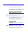
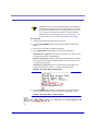
In Wireless ACE, select Dynamic IP to configure your modem to use IP Manager.
PinPoint-E EV-DO User Guide for Verizon, version 2.23
17
IP Manager
FIGURE 1.
Wireless ACE: Dynamic IP (IP Manager configuration)
1.
Modem name: The name you want for the modem.
2.
Domain: The domain name to be used by the modem.
3.
IP Manager IP Address: The IP or domain name of the dynamic DNS server
which is running IP Manager.
Note: To use the name here instead of the IP, you need to have
DNS set up in your PinPoint-E (page 19).
4.
IP Manager update interval: How often you want the address sent to IP Manager. If this is set to zero, the modem will only send an update if the IP changes
(i.e. if the modem is reset or is assigned a different IP).
You can configure a second dynamic server as a backup, secondary, or alternate
server.
Note: For the Modem Name, you should use something which is
unique but also easy to remember. Your company name or the
intended function of the modem are recommended. If you have
more than one modem, you can append a number for each.
Restrictions for Modem Name
•
•
•
•
18
Must begin with a letter or number
Can include a hyphen (-)
Cannot contain spaces
Must be no longer than 20 characters total
PinPoint-E EV-DO User Guide for Verizon, version 2.23
IP Manager
DNS: Using Names Instead of IP addresses
A domain name is a name of a server or device on the Internet which is associated,
generally, with an IP address. In a way, a domain name is like the street address of
your house with the phone number being like the IP address. You can contact the
house either by going to the address (name) or by calling the phone number (IP
address).
Domain Name Service (DNS) is a network service which translates, or redirects,
the IP address, allowing someone to contact that address via the name. A DNS
server is registered to handle all addresses of a particular domain (much like the
post office for a particular town or city is known to the post offices of all other
towns and cities and is authorized to give the addresses of locations in its own location).
Configuring DNS
The PinPoint-E has an internal DNS resolver with which it can query DNS servers
in order to translate names into IP addresss which it can then use internally. Generally, when your PinPoint-E receives its IP address from Verizon, it will also be configured to use Verizon’s DNS servers to use for resolving (or translating) names to
IP addresses. In that case, the only one which is not overwritten is the alternate
DNS.
You can use AT commands (page 64), Wireless ACE (page 10), and ACE Net
(page 11) using a template built from Wireless ACE to configure DNS in your PinPoint-E.
FIGURE 2.
Wireless ACE: DNS
PinPoint-E EV-DO User Guide for Verizon, version 2.23
19
IP Manager
*DNS1 and *DNS2 - Set these to your primary and secondary DNS servers.
These maybe be overwritten by Verizon when your PinPoint-E gets its IP
address.
*DNSUSER - Set this, if desired, to an additional DNS server to query first
before the primary or secondary (just as a hosts file is queried first on a computer). If *DNSUSER is set to 0.0.0.0, it will be ignored.
*DNSUPDATE - This command sets how often you want DNS Updates to be
forced. Otherwise the PinPoint-E will only send updates when it is reset, powered up, or the IP address granted by the network changes.
Note: If you will be using your PinPoint-E to communicate with
another AirLink modem and both are using IP Manager to translate dynamic IP addresss to domain names, it is recommended
that you set *DNSUSER to the IP address for IP Manager. IP
Manager’s updates occur more frequently than Verizon’s DNS
servers decreasing the time between IP address change and
address resolution.
20
PinPoint-E EV-DO User Guide for Verizon, version 2.23
CHAPTER 5
Keepalive
It is not uncommon for your PinPoint-E to be disconnected from Verizon after an
extended period of inactivity. This is generally a feature intended to reduce your
charges for inactive use.
Keepalive is used to test and maintain the PinPoint-E’s connection to Verizon by
pinging an IP address after a specified period of inactivity. Keepalive is recommended for users who have a remote terminated modem that infrequently communicates to the network. Keepalive is also recommended if you have experienced
issues where the modem can no longer be reached remotely.
When Keepalive pings the IP address, an acknowledgement indicates there is an
active connection to the network. If the modem does not receive a response from
the IP address, it will retry 5 times in 5 second intervals. The PinPoint-E will then
reset the radio module after 5 failed attempts and reconnect to Verizon.
Configuring Keepalive
As with all other aspects of the PinPoint-E’s configuration, you can use Wireless
Ace (page 10), AceNet (page 11), or Telnet (page 64) to configure Keepalive.
PinPoint-E EV-DO User Guide for Verizon, version 2.23
21
Keepalive
To set the Keepalive using Wireless ACE, select Other from the menu on the left.
FIGURE 1.
Wireless ACE: Keepalive Configuration
*IPPING sets the interval, in minutes, you want Keepalive to test the network
connection. To disable Keepalive, set *IPPING to 0 (default setting).
Note: 15 minutes is the minimum time which can be set for Keepalive.
*IPPINGADDR sets the IP address you want to use for the test. If *PPINGADDR is left blank or is set to an invalid IP address (i.e. an IP which is
unreachable or one which is not a valid IP address), the modem will reset itself
on a regular interval.
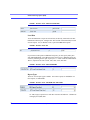
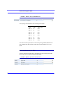
Data usage using Keepalive
When using Keepalive, be aware that a ping moves approximately 66 bytes of data
over the network and is billable by the carrier. The following *IPPING settings
will incur approximate monthly data usage in addition to any other data usage:
22
15 minutes
400k / month
30 minutes
200k / month
60 minutes
100k / month
120 minutes
50k / month
PinPoint-E EV-DO User Guide for Verizon, version 2.23
CHAPTER 6
External Inputs and
Power Control
The PinPoint-E has special features for use in a mobile environment. The PinPointE can be configured to monitor the inputs on its serial port and respond to specific
types of events. The PinPoint-E can also be configured to change its power mode
in order to conserve power.
Capturing Events via External Inputs
The RS232 DB9 interface (the serial port) can be connected to digital switches and
configured to capture contact closures using RTS and DTR to signal external or
physical events (such as a tow bar being activated, opening a door or trunk, the car
is turned on or off, etc.).
Setting the DTR and RTS
You can use either Wireless ACE (page 10), direct serial communication, or Telnet
to configure the modem using AT commands (page 64).
In Wireless ACE, select PinPoint from the menu on the left.
PinPoint-E EV-DO User Guide for Verizon, version 2.23
23
External Inputs and Power Control
FIGURE 1.
Wireless ACE: DTR and RTS
To turn on the DTR (pin 4) digital sensing in the modem, *DTRI should be set to 1.
To turn on the RTS (pin 7) digital sensing, *RTSI should be set to 1.
Note: To use only DTR or only RTS, you only need to configure
the one you will be using.
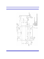
Connecting to the Serial Port
You can connect a standard RS232 serial cable to the The PinPoint-E serial port. If
you want to use the DTR switch, wire in a Normally Open switch between the DTR
(pin 4) and signal ground (pin 5), the PinPoint-E’s external case, or the power
ground (refer to the figures below). If you want to use the RTS switch, use RTS
(pin 7) to the ground (can use the same ground as DTR).
Caution: Never apply voltage to the DTR or RTS inputs. DTR
and RTS can only be switched open or closed to ground.
When the switch is closed, a GPS packet will be sent to the destination IP address
indicating that a contact closure has taken place (an external physical event has
occurred). See “RAP Configuration” on page 32.
FIGURE 2.
24
PinPoint-E back
PinPoint-E EV-DO User Guide for Verizon, version 2.23
External Inputs and Power Control
FIGURE 3.
PinPoint-E Serial Port Pinouts
DTR and RTS switches using Pin 5 (signal GND) as the common
ground (broche 5)
FIGURE 4.
Power Modes
The PinPoint-E can be configured to switch a low-power mode in response to specific events in order to conserve a vehicle's battery life.
PinPoint-EThe PinPoint-E can power down when the voltage to the modem drops
below a configured threshold (generally caused by the vehicle being turned off), or
when DTR changes (commonly a contact or voltage controlled by the key switch,
signaling when the vehicle is turned off).
PinPoint-E EV-DO User Guide for Verizon, version 2.23
25
External Inputs and Power Control
Note: If one or both DTR or RTS have been configured to be
used as digital inputs through the AirLink Tracking System
(ATS), then low power mode cannot be configured to respond to
DTR.
Power Effect on Modem State
Once the transition from powered on to low-power mode starts, the modem will
change state to AT mode. This results in the current mode being gracefully terminated. For the brief period when the modem is preparing for low-power mode, the
modem will remain in AT mode (i.e. won't auto-answer, ATD will fail, etc.). Once
low-power mode is entered, the modem will then discard any data received on the
host port.
When the modem is woken from low-power mode, the same behavior occurs as
upon power on. The modem starts in AT mode, and then after 5 seconds will enter
the default mode (See “Host Modes” on page 53).
26
PinPoint-E EV-DO User Guide for Verizon, version 2.23
CHAPTER 7
Global Positioning
System (GPS)
The PinPoint-E is equipped with a GPS receiver to ascertain its position to track the
movements of a vehicle or other devices which move. The PinPoint-E relays the
information of its location as well as other data for use with AirLink Tracking System (ATS) or other such tracking applications.
GPS Overview
The Global Positioning System (GPS) is a satellite navigation system used for
determining a location and providing a highly accurate time reference almost anywhere on Earth. The US military refers to GPS as Navigation Signal Timing and
Ranging Global Positioning System (NAVSTAR GPS).
GPS consists of a "constellation" of at least 24 satellites in 6 orbital planes. Each
satellite circles the Earth twice every day at an altitude of 20,200 kilometres
(12,600 miles). Each satellite is equipped with an atomic clock and constantly
broadcasts the time, according to its own clock, along with administrative information including the orbital elements of its motion, as determined by ground-based
observatories.
PinPoint-E EV-DO User Guide for Verizon, version 2.23
27
Global Positioning System (GPS)
A GPS receiver, such as the PinPoint-E, generally receives signals from four satellites in order to determine its own latitude, longitude, and elevation. Using time
synced to the satellite system, the receiver computes the distance to each satellite
from the difference between local time and the time the satellite signals were sent
(this distance is called psuedoorange). The locations of the satellites are decoded
from their radio signals and a database internal to the receiver. This process yields
the location of the receiver. Getting positioning information from fewer than four
satellites, using imprecise time, using satellites too closely positioned together, or
using satellites too close to the Earth’s curve will yield inaccurate data.
The GPS data is then transmitted to a central location which uses a tracking application to compile information about location, movement rates, and other pertinent
data.
AirLink Remote Access Protocol (RAP)
The AirLink Remote Access Protocol (RAP) uses the User Datagram Protocol
(UDP) and is a proprietary binary message format. RAP has been designed to work
specifically with AirLink Tracking System (ATS), but other 3rd party applications
have been developed to take advantage of the RAP messaging format. AirLink
RAP is also referred to as AirLink Binary/ATS.
National Marine Electronics Association (NMEA)
National Marine Electronics Association (NMEA) is a protocol by which marine
instruments and most GPS receivers can communicate with each other. NMEA
defines the format of many different GPS message (sentence) types, which are
intended for use by navigational equipment.
Trimble ASCII Interface Protocol (TAIP)
Trimble ASCII Interface Protocol (TAIP) is a digital communication interface
based on printable ASCII characters over a serial data link. TAIP was designed specifically for vehicle tracking applications but has become common in a number of
other applications, such as data terminals and portable computers, because of its
ease of use.
28
PinPoint-E EV-DO User Guide for Verizon, version 2.23
Global Positioning System (GPS)
Real-Time Clock Sync
Every hour, the PinPoint-E will sync the internal Real Time Clock (RTC) with the
Coordinated Universal Time (UTC) received from the GPS satellites.
Applications, such as ATS and the Event Browser, will then translate the time
reported by the PinPoint-E as part of the GPS message to the appropriate local time
zone using the UTC offset (i.e. California is UTC-8 and New York is UTC-5).
Note: Wireless ACE displays the current time (UTC) set in the
modem and does not translate it to the local time zone. If the
modem is in California and it is 8 a.m., the modem’s time will be
shown as 4 p.m, since UTC is 8 hours “ahead” of Pacific time.
Configuring the PinPoint-E for GPS
To configure your modem’s GPS settings, you can use either Wireless ACE or Telnet to configure the modem using AT commands (page 64). The configuration
examples in this chapter all use Wireless ACE. Most of the settings are in the menu
option: PinPoint.
The main sections below detail how to set up the configuration for RAP (page 32),
RAP special features (page 35), RAP Store and Forward (page 38), NMEA
(page 42), and TAIP (page 44). Most of the PinPoint-E commands are covered in
the main sections below.
Caution: With the PinPoint-E, all local GPS (UDP encapsulated)
reports will come over the Ethernet connection. Raw GPS data
can be transmitted across the serial port for applications which
require COM traffic.
Over-The-Air (Remote) Host
To set the PinPoint-E to report to an external or remote host, configure *PPIP (ATS
Server IP) and *PPPORT (Server Port). *PPIP will work an NMEA or TAIP
remote host as well as with an ATS remote host.
PinPoint-E EV-DO User Guide for Verizon, version 2.23
29
Global Positioning System (GPS)
FIGURE 1.
Wireless ACE: *PPIP and *PPPORT
Local Host
To set the PinPoint-E to report to an local host, one directly connected to the PinPinPoint-E’s Ethernet port, configure S53. The local IP will automatically be used
for local reports. S53, in Wireless ACE, is part of the Misc menu option.
FIGURE 2.
Wireless ACE: S53
If you need to send reports to additional local ports, you can specify other ports
with *PPLATSEXTRA. Local Reports can be sent to up to 7 additional ports consecutively following the S53 port. Specify 0 to 7. If S53=1000 and *PPLATSEXTRA=4, reports will be sent to 1000, 1001, 1002, 1003, and 1004.
FIGURE 3.
Wireless ACE: *PPLATSEXTRA
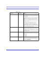
Report Types
There are several report types available. For remote reports, set *PPGPSR. For
local reports, set *PPLATSR.
FIGURE 4.
Wireless ACE: *PPGPSR and *PPLATSR
0 - *MF, Legacy reports for use with ATS version 4 and older. 11 - Global Positioning System (GPS) data.
30
PinPoint-E EV-DO User Guide for Verizon, version 2.23
Global Positioning System (GPS)
12 - GPS data with the UTC time and date.
13 - GPS with time and date and Radio Frequency data from the antenna. D0 Xora reports.
E0 - NMEA GGA and VTG sentences.
E1 - NMEA GGA, RMC, and VTG sentences.
F0 - TAIP data
F1 - TAIPcompact data
Note: The PinPoint-E can be configured to supply one type of
report to a remote host and different a report type locally through
the Ethernet port at same time. However, there may be conflicts
due to the local and remote reporting being in different modes
and not all features to both modes may be available.
Sending Reports Automatically
You can configure the PinPoint-E to send reports based on a time interval and on
the movement rate of a vehicle (based on it’s position from one time to the next).
FIGURE 5.
Wireless ACE: Automatic Reports
*PPTIME - Location report sent every set time interval (seconds).
*PPDIST - Location report sent only if the position is more than the set distance (x 100 meters).
*PPTSV - Location report sent if the vehicle has been in one location (stationary) for more than a set time interval (minutes).
*PPMINTIME - Location report sent be sent at no less than this time interval
(seconds).
If you are sending reports on the local Ethernet port, if you want them sent automatically, you will need to set *PPLATS. The time interval, just as for *PPTIME, is in
seconds.
PinPoint-E EV-DO User Guide for Verizon, version 2.23
31
Global Positioning System (GPS)
FIGURE 6.
Wireless ACE: Local Automatic Reports
The PinPoint-E can be configured to wait a specific amount of time after initialization before any reports are sent.
FIGURE 7.
Wireless ACE: GPS Initialization Timer
RAP Configuration
RAP is used with AirLink Tracking System and other applications. RAP has additional features which allow reports based on external physical events, input from a
COM1000 device, store and forward processing, etc.
Most of the configuration settings for RAP can be changed with the RAP configuration command message. Refer to the AirLink Tracking System User Guide.
RAP Reports Over-The-Air (Remote)
To configure the PinPoint-E to send RAP reports to a remote server, you will need
to set 3 commands: *PPIP, *PPPORT, and *PPGPSR.
FIGURE 8.
32
Wireless ACE: RAP Reports Remote
1.
Set the IP (*PPIP) and port (*PPPORT) to the IP and port of the server to which
you want the reports sent.
2.
Set the GPS Report Type (*PPGPSR) to your preferred RAP report type.
PinPoint-E EV-DO User Guide for Verizon, version 2.23
Global Positioning System (GPS)
11 - GPS - Global Positioning System data
12 - GPS + Date - GPS data with the UTC time and date
13 - GPS + Date + RF - GPS data with the UTC time and date and Radio Frequency information from the antenna.
If you need to use a dynamic IP for the ATS server, you can use the RAP configuration command to change the value for *PPIP (see below).
Note: If your PinPoint-E is on a mixed network (some of the
fleet on another cellular network), you will need to specify the
IP of the server in *PPIP and configure the PinPoint-E not to
change the server IP with a RAP configuration command using
*PPIGNOREIP. This will prevent the ATS server configuration
packets from changing the *PPIP value.
FIGURE 9.
Wireless ACE: *PPIGNOREIP
RAP Reports over a Local Connection (PPP or SLIP)
Local reports are sent to the local IP address of the computer or device connected to
the Ethernet port of the PinPoint-E using PPP or SLIP. To configure the modem to
send to the local IP, you will need to set 3 commands: S53, *PPLATS, and
*PPLATSR.
FIGURE 10.
Wireless ACE: RAP Local Reports
1.
Set the port (S53) to the local port to which you want the reports sent. The local
IP will automatically be used. S53, in Wireless ACE, is part of the Misc menu
option.
2.
Set the ATS Local Report Type (*PPLATSR) to your preferred RAP report type.
PinPoint-E EV-DO User Guide for Verizon, version 2.23
33
Global Positioning System (GPS)
11 - GPS - Global Positioning System data
12 - GPS + Date - GPS data with the UTC time and date
13 - GPS + Date + RF - GPS data with the UTC time and date and Radio Frequency information from the antenna.
3.
Set Local ATS Reporting Time Interval (*PPLATS) to the number of seconds
you want as an interval between reports being sent. If *PPLATS is set to 0,
reports will only be sent if a poll command is issued by the local client.
RAP Message format
RAP uses the UDP transport protocol to deliver messages between the Server and
the PinPoint-E. The Server is the master and sends commands to one or more PinPoint-E devices. Each PinPoint-E returns command status and responses to the
Server.
For reliability, the server expects each command to be acknowledged within a timeout period. If the acknowledgement packet (ACK) is not received within the timeout period, the server will retransmit the command.
The RAP messages are in Hex and are referred to by their message ID.
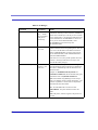
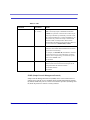
Commands
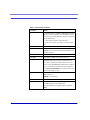
0x02 Request a location report from a PinPoint-E.
0x05 Request the PinPoint-E configuration.
0x06 Configure the PinPoint-E.
0x08 Set the PinPoint-E odometer.
0x09 Request the current PinPoint-E odometer setting.
0x11 Request a simple GPS report.
0x12 Request a simple GPS report with the date included (the time will be in
UTC).
0x13 Request a simple GPS report with the date and radio frequency information included.
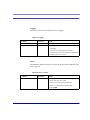
Power Reports
0x10 Power Up Report - Sent by the modem when it is powered up (either as a
result of being power cycled or with a software reset).
34
PinPoint-E EV-DO User Guide for Verizon, version 2.23
Global Positioning System (GPS)
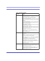
0x30 Power Sleep Report - Sent by the modem when it is about to power down
into a low-power state (not supported in some early PinPoint models).
0x31 Power Wakeup Report - Sent by the modem when it is returned to a full
power state from a low-power state (not supported in some early PinPoint models)
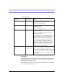
GPS Reports
0x11 Simple GPS Report - Report contains GPS latitude and longitude in 1/
100,000 degrees, GPS velocity in kilometers/hour, GPS Direction in 2 degree
increments, UTC time (but not date), GPS satellite count and quality, and
optional data
0x12 Simple GPS Report with the addition of the UTC date.
0x13 Simple GPS Report with the addition of the UTC date and including radio
frequency data with the GPS point.
0x20-0x23 indicate the state changes of either the RTS or DTR (See “Store and
Forward for RAP” on page 38) in addition to the same data as in an 0x12 report.
0x24-0x2B indicate the state changes of the COM1000 inputs (See “COM1000
Event Reports” on page 37) in addition to the same data in an 0x12 or 0x13
report.
Note: It is recommended to use Report type 0x12 or 0x13 when
Store and Forward (page 38) is enabled.
Additional RAP Features
RAP allows additional information to be sent with or as the reports to enable a
richer tracking feature set. Configure RAP as you would normally for remote or
local reports (See “RAP Configuration” on page 32).
Device ID
By enabling *PPDEVID, the device ID is sent as part of the RAP message to make
identification easier in a network or fleet of vehicles equipped with PinPoint-E
modems.
PinPoint-E EV-DO User Guide for Verizon, version 2.23
35
Global Positioning System (GPS)
Wireless ACE: *PPDEVID
FIGURE 11.
Caution: If the PinPoint-E is using a dynamic IP, *PPDEVID
needs to be enabled.
Generally, the device ID the PinPoint-E will use is the IP or phone number assigned
by Verizon.
Odometer Data in Reports
When the odometer is enabled, the PinPoint-E will calculate distance based on GPS
data. The modem’s odometer calculations can be included in the RAP message.
FIGURE 12.
Wireless ACE: Odometer Reports
Note: The PinPoint-E’s odometer calculations may not match the
odometer in the vehicle itself. The PinPoint-E odometer is not
connected to the vehicle’s, it is entirely based on calculations of
GPS readings.
Serial Input Event Reports
You can configure the PinPoint-E to send reports based on the state of the DTR
and/or RTS pins on the serial port. Refer to “Capturing Events via External Inputs
on“page 23 to set up the external devices.
Once the serial port has been connected, you will also need to enable the event
reporting for GPS.
36
PinPoint-E EV-DO User Guide for Verizon, version 2.23
Global Positioning System (GPS)
FIGURE 13.
Wireless ACE: Enabling RTS and DTR for Input Events
f you have connected the physical device to the RTS pin and ground, you will need
to enable RTSI. If you have connected it to the DTR pin and ground, you will need
to enable DTRI. You can have different devices connected to each. If you have
two connected, enable both.
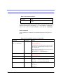
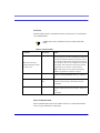
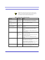
To enable the reports themselves, use *PPINPUTEVT.
FIGURE 14.
Wireless ACE: Input Event Reports
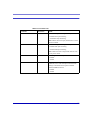
The report type will indicate the state of change in either RTS or DTR.
Input
Value
Report Type
DTR
0
0x20
DTR
1
0x21
RTS
0
0x22
RTS
1
0x23
The contents of the report will be the same as Report Type 0x12 (GPS data with
date) with the addition of the event report (page 34).
COM1000 Event Reports
Support for the COM1000 is enable with the register *PPCOM1000=1 (0 = off
[default], 1 = on). Once enabled, ALEOS will receive the UDP packets from a
properly configured COM1000 and add the state of the extra inputs to RAP packets
sent to ATS.
PinPoint-E EV-DO User Guide for Verizon, version 2.23
37
Global Positioning System (GPS)
FIGURE 15.
Wireless ACE: COM1000 Events
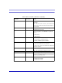
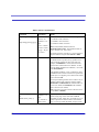
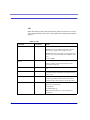
The report type will indicate the state of change in the inputs.
Input
Value
Report Type
INPUT 1
LO
0x24
INPUT 1
HI
0x25
INPUT 2
LO
0x26
INPUT 2
HI
0x27
INPUT 3
LO
0x28
INPUT3
HI
0x29
INPUT 4
LO
0x2A
INPUT 4
HI
0x2B
The contents of the report will be the same as Report Type 0x12 (GPS data with
date) or 0x13 (GPS data with date and RF data) with the addition of the event
report.
Store and Forward for RAP
The Store and Forward (SnF) allows the PinPoint-E to store messages and send
them to the server in a packet rather than individually.
FIGURE 16.
38
Wireless ACE: Store and Forward
PinPoint-E EV-DO User Guide for Verizon, version 2.23
Global Positioning System (GPS)
Once you have enabled SnF, *PPSNF, you can determine how you want the messages sent using *PPSNFB, Store and Forward Mode:
Normal - Each report is sent immediately.
Polled - Reports held until requested by the server.
Grouped - Reports held until total is equal or greater than *PPSNFM which
sets the packet size of grouped reports.
Store and Forward Reliable Mode
The Store and Forward Reliable Mode allows the PinPoint-E to ensure all messages
are received by the server even if the connection between them goes down for a
period of time (such when a vehicle passes through a location where the cellular
signal is weak or non-existent).
FIGURE 17.
Wireless ACE: Store and Forward Reliable Mode
With Reliable Mode enabled, *PPSNFR, the PinPoint-E will transmit a sequence
number (1 to 127) as part of a packet of messages (may contain one or more
reports). To reduce overhead, the server only acknowledges receipt of every eighth
packet. The PinPoint-E considers that 8 a “window” of outstanding packets.
If the PinPoint-E doesn’t receive acknowledgement for a “window”, the modem
will PING the server with a message containing the sequence numbers of the first
and last packets that haven’t been acknowledged. The PinPoint-E will continue
until the server acknowledges receipt. When the PinPoint-E receives the acknowledgement, it will advance its “window” to the next group.
When the PinPoint-E is first powered on (or reset), it will send a Set Window message to sync up with the server for the current “window”.
On the other side, if the server receives and out of sequence packet, it will send a
message to the modem noting the missing sequence and the PinPoint-E will retransmit.
GPS Time, Latitude, and Longitude can be added, *UDPRGPS, to the packet
sequence data for Reliable Mode.
PinPoint-E EV-DO User Guide for Verizon, version 2.23
39
Global Positioning System (GPS)
Wireless ACE: Adding GPS Time, Latitude, and Longitude to
Reliable UDP data
FIGURE 18.
Sending Reports
You can configure the PinPoint-E to send reports based on a time interval and on
the movement rate of a vehicle (based on it’s position from one time to the next).
FIGURE 19.
Wireless ACE: Automatic Reports
*PPTIME - Location report sent every set time interval (seconds).
*PPDIST - Location report sent only if the position is more than the set distance (x 100 meters)
*PPTSV - Location report sent if the vehicle has been in one location (stationary) for more than a set time interval (minutes).
*PPMINTIME - Location report sent be sent at no less than this time interval
(seconds).
Flush on Event
If you have events enabled, with *PPFLUSHONEVT, you can configure the PinPoint-E to flush the SnF buffer when an event occurs. This will drop all outstanding packets and not transmit or retransmit them.
FIGURE 20.
40
Wireless ACE: Store and Forward Flush on Event
PinPoint-E EV-DO User Guide for Verizon, version 2.23
Global Positioning System (GPS)
Note: Outstanding packets can include messages already sent to
the server that haven’t been acknowledged (SnF Reliable Mode)
whether they have been received by the server or not.
Legacy ATS/RAP
If your ATS server is running ATS version 4 or older, then you will need to configure the PinPoint-E to send an earlier version of RAP. If you want to send the legacy
message to a remote server, you will need to configure *PPGPSR to *MF. If you
want to sent the legacy messages locally (over the Ethernet port) you will need to
configure *PPLATSR to *MF. IP and port configuration is as above for other RAP
configurations.
FIGURE 21.
Wireless ACE: *PPGPSR and *PPLATSR
You will also need to specify the type of Legacy format, *MF, you are using. The
format is specified in hex.
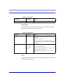
FIGURE 22.
Wireless ACE: Legacy format
8A - Transmit Latitude, Longitude, and Time
8E - Transmit Latitude, Longitude, Direction, Velocity and Time
8F - Transmit Latitude, Longitude, Direction, Velocity, Time, and GPS satellite
quality
PinPoint-E EV-DO User Guide for Verizon, version 2.23
41
Global Positioning System (GPS)
NMEA Configuration
The PinPoint-E transmits standard NMEA GPS messages as well as the proprietary
RAP format.
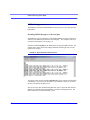
Streaming NMEA Messages over the local port
The PinPoint-E can be configured to send standard NMEA messages (sentences) in
ASCII over the Ethernet port from the local computer. For examples of the message format descriptions, refer to page 110.
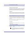
Send the command ATGPS1 to the Ethernet port to begin the NMEA stream. The
example below shows the stream in HyperTerminal connecting directly to a PinPoint via the comport.
FIGURE 23.
HyperTerminal: NMEA Stream
To stop the stream, use the command ATGPS0 (this can be entered even while data
is streaming). You can also use AT*PGPS=1 then AT&W to allow you to stream
the data even after the modem is reset.
You can also issue this command using Wireless ACE to stream the data from the
Ethernet port without using HyperTerminal or another terminal application. The
data will stream even after the modem is reset.
42
PinPoint-E EV-DO User Guide for Verizon, version 2.23
Global Positioning System (GPS)
FIGURE 24.
Wireless ACE: NMEA Strings
NMEA Messages Over-The-Air (Remote)
To configure the PinPoint-E to send NMEA reports to a remote server, you will
need to set 3 commands: *PPIP, *PPPORT, and *PPGPSR.
FIGURE 25.
Wireless ACE: NMEA Remote Reports
1.
Set the IP (*PPIP) and port (*PPPORT) to the IP and port of the server to which
you want the reports sent.
2.
Set the GPS Report Type (*PPGPSR) to your preferred NMEA sentence format.
E0 - Output the GGA and VTG sentences.
E1 - Output the GGA, RMC, and VTG sentences.
NMEA Messages over a Local Connection
Local reports are sent to the local IP address of the computer or device connected to
the Ethernet port of the PinPoint-E. To configure the modem to send to the local
IP, you will need to set 3 commands: *S53, *PPLATS, and *PPLATSR.
FIGURE 26.
Wireless ACE: NMEA Local Reports
PinPoint-E EV-DO User Guide for Verizon, version 2.23
43
Global Positioning System (GPS)
1.
Set the port (S53) to the local port to which you want the reports sent. The local
IP will automatically be used. S53, in Wireless ACE, is part of the Misc menu
option.
2.
Set the ATS Local Report Type (*PPLATSR) to your preferred NMEA sentence
format.
E0 - Output the GGA and VTG sentences.
E1 - Output the GGA, RMC, and VTG sentences.
3.
Set Local ATS Reporting Time Interval (*PPLATS) to the number of seconds
you want as an interval between reports being sent.
TAIP Emulation Configuration
The TAIP emulation functionality allows the PinPoint-E to operate in a limited
manner with clients which only understand the Trimble ASCII Interface Protocol
(TAIP).This emulation is enabled by setting the GPS report format, directing the
modem to listen for TAIP messages, and disabling AirLink Binary/ATS formatted
messages. For the message format descriptions, refer to page 113.
TAIP Messages Over-the-Air (Remote)
To configure the PinPoint-E to send TAIP reports to a remote server, you will need
to set 3 commands: *PPIP, *PPPORT, and *PPGPSR.
FIGURE 27.
44
Wireless ACE: TAIP Remote Reports
1.
Set the IP (*PPIP) and port (*PPPORT) to the IP and port of the TAIP server.
2.
Set GPS Report Type (*PPGPSR) to F0-TAIP data.
PinPoint-E EV-DO User Guide for Verizon, version 2.23
Global Positioning System (GPS)
Note: Unlike standard TAIP which simply sends to the last client
to request automatic reports, the remote reports are sent to the
destination address (*PPIP) and destination port (*PPPORT).
TAIP Messages over a Local Connection
Some TAIP client applications can send TAIP requests and listen for reports using a
local connection. Generally this is done over the Ethernet port. To configure this
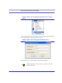
option, you will need to set four commands: *PPIP, S53, *PPGPSR, and *PPLATS.
FIGURE 28.
Wireless ACE: TAIP Local Reports
1.
Set the IP (*PPIP) to the local IP of the PinPoint-E.
2.
Set the port (S53) to 21000. The local IP will automatically be used. S53, in
Wireless ACE, is part of the Misc menu option.
3.
Set GPS Report Type (*PPGSPR) to F0 - TAIP Data.
4.
Set the Local ATS Reporting Time Interval (*PPLATS) to 0 to disable unsolicited local reports.
With this configuration, the PinPoint-E will listen for TAIP requests on the local IP
(192,168.13.31 by default) and port 21000. Once a TAIP request command has
been received, the PinPoint-E will begin issuing TAIP reports (e.g. DPVs) to the
local IP and port 21000. The client application should be listening for reports on
this IP address and port.
No unsolicited reports will be sent from the PinPoint-E to the local client application.
PinPoint-E EV-DO User Guide for Verizon, version 2.23
45
Global Positioning System (GPS)
Sending Unsolicited TAIP Messages over a Local Connection
Standard TAIP requires a request before GPS reports are sent. The PinPoint-E,
however, can be configured to allow TAIP formatted messages to be sent over any
UDP Port without request commands. This is useful for those applications which
can listen for TAIP messages but cannot send UDP request packets.
This configuration sends TAIP GPS reports to whatever address and UDP Port you
select. You will need to set 3 commands: S53, *PPLATS, and *PPLATSR.
FIGURE 29.
Wireless ACE: TAIP Local Reports, Unsolicited
1.
Set the port (S53) to 1000. The local IP will automatically be used. S53, in
Wireless ACE, is part of the Misc menu option.
2.
Set ATS Local Report Type (*PPLATSR) to F0 - TAIP Data.
3.
Set the Local ATS Reporting Time Interval (*PPLATS) to 5 to send reports
every 5 seconds (can be adjusted as circumstances warrant).
Using TAIP Command Emulation
To configure the PinPoint-E to use TAIP emulation set GPS Report Type (*PPGSPR) to F0 - TAIP Data.
FIGURE 30.
Wireless ACE: TAIP Emulation
Note: With TAIP emulation, the PinPoint-E will listen for TAIP
messages on port 21000. AirLink Protocol (RAP) will be disabled and no RAP messages or commands will be sent or
received on that port.
46
PinPoint-E EV-DO User Guide for Verizon, version 2.23
Global Positioning System (GPS)
TAIP ID
The TAIP messages can be configured to send the user specified identification
number (ID). This greatly enhances the functional capability of the unit in a network environment. Set the ID using *PPTAIPID.
FIGURE 31.
Wireless ACE: TAIP ID
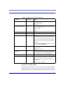
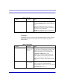
Supported TAIP Commands
The TAIP emulation will accept the following TAIP message types:
SRM allows the client to set the reporting mode configuration. The report mode
configuration is not stored in non-volatile memory and such should be reset
upon a unit reset. This behavior emulates that specified in TAIP specifications.
QRM reports the reporting mode configuration (returns an "RRM" message).
SID allows the client to set the TAIP ID (AT*PPTAIPID can also be used to set
the TAIP ID). The TAIP ID, when set with a "SID" message, will be written to
non-volatile memory.
QID reports the TAIP ID (returns an "RID" message).
DPV configures automatic reporting of PV (Position/Velocity) reports based on
distance traveled and a maximum time. The delta distance value specified in the
message is converted to hundreds of meters and stored as *PPDIST. The maximum time interval is stored as *PPTIME. Currently the minimum time and
epoch values are ignored.
FPV configures periodic reporting of PV (Position/Velocity) reports. The time
interval from the message is stored at *PPTIME. Currently the epoch value is
ignored.
QPV responds with a PV (Position/Velocity) report.
The TAIP emulation will generate the following reports corresponding to the
appropriate event (either a query for it, echoed due to a set, or due to an automatic
reporting event).
RRM reports the reporting mode configuration.
RID reports the TAIP ID.
RPV reports Position/Velocity.
PinPoint-E EV-DO User Guide for Verizon, version 2.23
47
CHAPTER 8
Simple Network
Management Protocol
(SNMP)
The PinPoint-E can be configured as an SNMP agent and supports SNMPv2c and
SNMPv3.
SNMP Overview
The Simple Network Management Protocol (SNMP) was designed to allow remote
management and monitoring of a variety of devices from a central location. The
SNMP management system is generally composed of agents (such as your PinPoint-E, a router, a UPS, a web server, a file server, or other computer equipment)
and a Network Management Station (NMS) which monitors all the agents on a specific network. Using the management information base (MIB), an NMS can
include reporting, network topology mapping, tools to allow traffic monitoring and
trend analysis, and device monitoring.
Authentication ensures SNMP messages coming from the agent, such as the PinPoint-E, have not been modified and the agent may not be queried by unauthorized
users. SNMPv3 uses a User-Based Security Model (USM) to authenticate and, if
desired or supported, message encryption. USM uses a user name and password
specific to each device.
PinPoint-E EV-DO User Guide for Verizon, version 2.23
48
Simple Network Management Protocol (SNMP)
Management Information Base (MIB)
The management information base (MIB) is a type of database used to compile the
information from the various SNMP agents. Reports from various agents, such as
the PinPoint-E, are sent as data in form designed to be parsed by the NMS into its
MIB. The data is hierarchical with entries addressed through object identifiers.
SNMP Traps
The trap is a “snap-shot” of the settings and status of the Agent’s device which is
sent as a report to the NMS in a form that can be parsed and stored in the MIB. For
an example of the trap from an AirLink modem refer to the Appendix, page 100.
PinPoint-E SNMP Configuration
To configure your PinPoint-E to work as an SNMP agent, you can use either Wireless ACE, direct serial communication or Telnet to configure the modem using AT
commands (page 53). In Wireless ACE, the SNMP commands are all on the Other
menu option.
There are only three commands to set for SNMP in the PinPoint-E: the listening
port, the security level, and the trap destination.
Listening Port
*SNMPPORT sets the port for the SNMP agent to listen on. If set to zero, default,
SNMP is disabled.
FIGURE 1.
Wireless ACE: *SNMPPORT
Note: SNMP generally uses port 161, however most Internet pro-
viders (including cellular) block all ports below 1024 as a security measure. You should be able to use a higher numbered port
such as 10161.
PinPoint-E EV-DO User Guide for Verizon, version 2.23
49
Simple Network Management Protocol (SNMP)
Security Level
*SNMPSECLVL sets the security level and which version of SNMP communications are used.
FIGURE 2.
Wireless ACE: *SNMPSECLVL
0 - No security required. SNMPv2c and SMNPv3 communications are allowed.
1 - Authentication required. SNMPv3 is required to do authentication and
SNMPv2c transmissions will be silently discarded. Authentication is equivalent
to the authNoPriv setting in SNMPv3.
2 - Authentication required and messages are encrypted. SNMPv3 is required
to do authentication. SNMPv2c and SNMPv3 authNoPriv transmissions will be
silently discarded. Authentication and encryption is equivalent to the authPriv
setting in SNMPv3.
User Name and Password
The user name is 'user'. The user name cannot be changed.
The PinPoint-E's password is used as the SNMP password (default is '12345').
Note: The eight-character password requirement for SMNPv3 is
not enforced by the PinPoint-E's Agent to allow the default password to function. Your SNMP administrator or MIS may require
you to change to a more secure and/or longer password.
To change the password in the PinPoint-E, select Modem from the top menu line in
Wireless ACE.
50
PinPoint-E EV-DO User Guide for Verizon, version 2.23
Simple Network Management Protocol (SNMP)
FIGURE 3.
Wireless ACE: Changing the PinPoint-E Password - Menu
Option
The current password will be pre-entered. As you type the new password and confirm it, the characters you type will be obscured by “x”.
FIGURE 4.
Wireless ACE: Changing the PinPoint-E Password
For the password, you can use numbers, letters, and/or punctuation.
Caution: The password is case sensitive. “drowssaP” is not the
same as “drowssap”.
PinPoint-E EV-DO User Guide for Verizon, version 2.23
51
Simple Network Management Protocol (SNMP)
Trap Destination
*SNMPTRAPDEST needs to be set with the destination IP and port. If either are
set to zero or empty, SNMP traps are disabled.
FIGURE 5.
Wireless ACE: *SNMPPORT
Note: Traps are sent out according to the SNMP security level
(i.e. if the security level is 2, traps will be authenticated and
encrypted). Currently, the only trap supported is LinkUp.
52
PinPoint-E EV-DO User Guide for Verizon, version 2.23
CHAPTER 9
Host Modes
The PinPoint-E plays the part of a host when its Ethernet port is connected to a
computer or another device. As the host,the PinPoint-E can be in one of two communication modes.
AT: The PinPoint-E accepts and responds to standard, Hayes-style AT commands.
PassThru: Direct connection to internal hardware (OEM Module) of the PinPoint-E.
By default, the PinPoint-E is in AT Mode and allows AT Commands to be entered
via Telnet (through the Ethernet port connection) or remotely (through the cellular
network).
PassThru Mode can only be exited by resetting the modem.
AT Mode
AT commands are used to configure the modem, command it to do something, or
query a setting. For a full listing of the AT commands, refer to page 64.
PinPoint-E EV-DO User Guide for Verizon, version 2.23
53
Host Modes
AT commands must always be terminated by <CR> (ASCII character 0x0D).
If E=1 (Echo On), the AT command (including the terminating <CR>) will be
displayed (output) before any responses.
Two settings affect the format of AT command output: V (Verbose) and Q (Quiet).
If Q=1 (Quiet On), no result codes are output whatsoever, so there is no
response generated by a (non query) command.
If Q=0 (Quiet Off), result codes are output. The format of this output is then
affected by the Verbose setting.
If Quiet mode is off, the result code is affected as follows:
For V=1 (Verbose mode), the textual result code is surrounded by <CR><LF>
and any AT query response is also surrounded by <CR><LF>.
For V=0 (Terse mode), a numeric result code is output with a single trailing
<CR> (no <LF> is output), while any AT query response is followed by
<CR><LF> (there is no preceding output).
For example, possible output to the AT command "AT<CR>" (assuming quiet
mode is not on) is:
<CR> - if V=0
<CR><LF>OK<CR><LF> - if V=1
PassThru Mode
In PassThru mode, the PinPoint-E does not behave normally, all Ethernet port communication is passed directly between the internal hardware and the computer connected directly to the modem. This mode can be used to configure hardwarespecific settings (e.g., for provisioning, etc.).
Issuing the "AT\APASSTHRU" enters this mode. The modem responds with OK,
at which point a direct connection to the internal hardware is established.
Some internal hardware requires upwards of 20 seconds before AT commands can
be entered, so be patient if there seems to be no response to AT commands.
54
PinPoint-E EV-DO User Guide for Verizon, version 2.23
Host Modes
Caution: PassThru can only be exited by resetting or power-
cycling the modem. This mode cannot be entered via a Telnet
session.
PassThru Mode allows only specific AT commands. Those commands which are
used with ALEOS only will be unavailable. The commands usable also depend
heavily on the modem model number (found on the label on the top of the modem).
Caution: ALEOS is disabled in PassThru Mode. You cannot use
most ALEOS specific commands while the modem is in
PassThru Mode.
PinPoint-E EV-DO User Guide for Verizon, version 2.23
55
CHAPTER 10
Hardware Installation
Your AirLink PinPoint-E should be mounted in a position that allows easy access
for the cables so they are not bent or constricted. The LEDs on the front panel
should be visible for ease of operational verification. You should ensure that there
is adequate airflow around the modem but that it is kept free from direct exposure
to the elements (sun, rain, etc.). The exterior of the case should also be grounded.
Possible locations for your PinPoint-E installed in a vehicle are in a trunk away
from where luggage or other items won’t be likely to dislodge it, under or in the
console, or behind seats. Ensure the location is secure both against abrupt movements of the vehicle and from other items coming into contact with the modem.
An optional accessory for your modem is a mounting kit. The bracket is designed
to snugly cradle the modem and hold it in place where you need it. See “Mounting
Kit” on page 62.
Connecting the Antennas
Your PinPoint-E will work with most standard cellular antennas with a connector
and rated to work with EV-DO technology. Connect the primary antenna or primary
RF cable directly to the connector on the back of the PinPoint-E.
PinPoint-E EV-DO User Guide for Verizon, version 2.23
56
Hardware Installation
To provide for diversity in the signal reception and broadcast, connect the second
cable or magnetic mount base directly to the second antenna port (SMA, marked
Rx Div) on the back of the PinPoint-E.
Use of receive diversity is optional. Data transmission and reception
will not be adversely affected if it is not used.
Your PinPoint-E will work with most standard active GPS antennas. Connect the
antenna or cable directly to the threaded connector.
FIGURE 1.
PinPoint-E connecters
GPS
Primary
Cellular
Receive
Diversity
Connecting power
Your PinPoint-E can be used with either DC (available in most automobiles) or 110
AC (standard US wall power) with the appropriate power adapter (available from
AirLink).
The power cable positive lead should be connected to the battery or power source
positive terminal. The power cable negative lead should be connected to the battery
or power source negative terminal. The PinPoint-E has an internal polysilicon circuit breaker that opens at 0.5 to 1.0 amps of current.
PinPoint-E EV-DO User Guide for Verizon, version 2.23
57
Hardware Installation
Connecting the PinPoint-E to a computer or other
device
Your PinPoint-E’s serial port can be connected directly to most computers or other
devices using a standard straight through cable. If you have a DCE device, you will
need a null modem or null modem cable.
The PinPoint-E’s Ethernet port can be connected directly to a computer or other
Ethernet device using a cross-over cable. If you are connecting the modem to a hub
or switch you should use a straight through cable or use the uplink port on the hub
or switch with a cross-over cable. Some newer computers have an auto-sensing
Ethernet port. You can use a straight through cable with computers so equipped.
Your PinPoint-E can also be connected to a USB to Ethernet device connected to a
computer or other device which does not have an available Ethernet port but does
have USB.
On some computers, the TCP receive window may be set to 16
kbytes. To optimize the throughput of your PinPoint-E, it is recommended that you change the TCP window to 128 kbytes to
256 kbytes using a TCP Optimizer.
You can obtain a TCP Optimizer, with instructions on how to
change the setting, from your local computer retailer or as a
download from the Internet using Google or another search
engine (search for “TCP Optimizer”). One TCP Optimizer
which AirLink has used successfully is from http://
www.speedguide.net.
58
PinPoint-E EV-DO User Guide for Verizon, version 2.23
APPENDIX 1
Specifications for the
PinPoint-E EV-DO
Physical Characteristics:
•
•
•
•
•
•
•
•
Weight: 2 lb.
Size: 6.8” x 3.3” x 2”
RF Antenna Connector: 50 Ohm TNC
Receive Diversity RF Antenna Connector: 50 Ohm SMA
GPS Antenna Connector: SMA
Ethernet Interface: RJ-45 Connector, 10 Base-T
Serial Interface:RS232 DB-9Fwith 1200-115200 bps
Status LEDs
Data Services & RF Features: EV-DO
•
•
•
•
Full duplex transceiver
Dual-band support for both 800 MHz cellular and 1.9 GHz PCS bands
Dual band Receive Diversity
CDMA 1xEV-DO (IS-856)
PinPoint-E EV-DO User Guide for Verizon, version 2.23
59
Environmental:
• Operating ranges: -30°C to +70°C
• Humidity: 5%-95% Non-condensing
Power Management:
•
•
•
•
•
Low power consumption
Dormant connection (idle for 10-20 seconds): 60 mA at 12 VDC
Input Voltage: 10 VDC to 28 VDC
Input Current: 20 mA to 350 mA
Low power mode: at 12 VDC
Power consumption
Modem
Idle
Transmitting
PinPoint-E
180 mAh
300 mAh
Serial Port Pin-outs
The cable between the modem and a computer or other serial device needs to be
wired straight-through (pin 1 goes to pin 1, pin 2 to pin 2, etc).
PinPoint-E EV-DO User Guide for Verizon, version 2.23
60
PinPoint-E EV-DO User Guide for Verizon, version 2.23
61
APPENDIX 2
Mounting Kit
An optional accessory for your modem is a mounting kit. The bracket is designed
to snugly cradle the modem and hold it in place where you need it.
The PinPoint-E “snaps” into place in the bracket locking into the grooves on the
PinPoint-E case. The bracket can be further secured with a twist-tie set into the
grooves on the top for situations where the modem may be subjected to violent
movement, such as in the back of an automobile. In most stationary installations,
such as in a field or pipe, the PinPoint-E and bracket shouldn’t require a twist-tie.
The bracket can be attached to the location using #6 screws (mounting hole diameter approximately 0.150").
FIGURE 1.
PinPoint-E Mounting Bracket, part number 100-170-1005
PinPoint-E EV-DO User Guide for Verizon, version 2.23
62
PinPoint-E EV-DO User Guide for Verizon, version 2.23
63
APPENDIX 3
AT Commands
Just as with a Hayes compatible analog modem, the PinPoint-E parameters can all
be configured with AT commands.
Using Wireless Ace
Wireless ACE is a graphical interface for the AT commands and it is highly recommended that you this utility to modify any parameters, however a terminal emulation application, such as Telnet, see below, can be used instead.
With Wireless ACE, you only need to find the command listed and then enter the
new value in the space provided. For those commands which have specific parameters, the choices will be in a drop down menu.
Note: Nearly all examples of entering commands in this User
Guide are using Wireless ACE.
PinPoint-E EV-DO User Guide for Verizon, version 2.23
64
FIGURE 1.
Wireless ACE: Using AT Commands
To set or commit the changes in the modem, use the Write button at the top of
Wireless ACE interface.
FIGURE 2.
Wireless ACE: Toolbar
For more information on using Wireless ACE 3G or Wireless ACE Web, please
refer to the Wireless ACE 3G User Guide.
Note: Some of the AT Commands are not able to be configured
in Wireless ACE 3G.
With Wireless ACE, you can create a template from one modem and
then use that template to configure other modems in the exact same
way. You can use a in AceNet, too, to configure several modems the
same all at once.
Using Telnet Terminal Emulation
It is possible to communicate with the PinPoint-E across a TCP/IP network. Telnet
provides a terminal style connection to the PinPoint-E.
Most installations of Microsoft Windows come with a version of HyperTerminal
(used here for specific directions), but you can use any other Telnet application,
such as Putty.
PinPoint-E EV-DO User Guide for Verizon, version 2.23
65
Start>All Programs>Accessories>Communications>HyperTerminal
1.
Choose a name for your connection, such as PinPoint-E or AirLink. The name
and icon are only for your own reference so you can find the connection at a
later date (if you want to have a connection saved for both local and remote, it is
recommended the connection name reflect the connection type, i.e. PinPoint-E
Remote).
FIGURE 3.
2.
Select TCP/IP (Winsock) for Connect Using. Then, if the modem is connected
directly to your computer’s Ethernet port, put in the host address of
192.168.13.31 or the *HOSTIP. If the modem is remote, the host address will
be the current Internet IP of the PinPoint-E. Change the port number to 2332
(default telnet port for the PinPoint-E).
FIGURE 4.
3.
66
HyperTerminal: Connection Name
HyperTerminal: TCP/IP Settings
When HyperTerminal connects to the PinPoint-E, you may be prompted for a
password. The default password is 12345. When you press Enter, you should
get back a reply of “OK”.
PinPoint-E EV-DO User Guide for Verizon, version 2.23
FIGURE 5.
HyperTerminal: AT mode via Telnet
4.
Type AT and press Enter. You should get a reply of “OK” or “0”.
5.
To see what you are typing as you type it, you will need to turn on the echo and
verbose mode. Type ATE1V1 and press Enter.
If you get a reply of “OK”, then you entered the command successfully. If you get
a reply of “0” or “ERROR”, try entering the command again.
Direct Serial Connection
Using HyperTerminal included with most installations of Microsoft Windows:
Start>All Programs>Accessories>Communications>HyperTerminal
1.
Choose a name for your connection, such as PinPoint-E or AirLink (if you
want to have a connection saved for both local and remote, it is recommended
the connection name reflect the connection type, i.e. PinPoint-E local). The
name and icon are only for your own reference so you can find the connection at
a later date.
FIGURE 6.
HyperTerminal: Connection Name
PinPoint-E EV-DO User Guide for Verizon, version 2.23
67
2.
Select COM1 for the Connect Using.
FIGURE 7.
3.
HyperTerminal: Comport Setting
Change the Bits per Second to 115200 (default), Data Bits to 8, Parity to
None, Stop Bits to 1, and Flow Control to Hardware.
FIGURE 8.
HyperTerminal: Comport Settings
4.
Type AT and press Enter. You should get a reply of “OK” or “0”. .
5.
To see what you are typing as you type it, you will need to turn on the echo and
verbose mode. Type ATE1V1 and press Enter.
6.
If you get a reply of “OK”, then you entered the command successfully. If you
get a reply of “0” or “ERROR”, try entering the command again.
AT Command Tables
The tables below list the AT commands, their parameters, and explain what they do.
• For most commands, you need to preface the command with AT (exceptions are
noted), i.e. ATA which listed as A
68
PinPoint-E EV-DO User Guide for Verizon, version 2.23
• Some commands have specific parameters while other commands will take
whatever your type.
• Acceptable parameters and/or specific formats are in the parameters column.
• Required variable parameters are denoted with italicized text, ex. Dn. The n is
variable and noted in the parameters column.
• Optional parameters are denoted with square brackets [ ].
• Most commands with parameters can be entered with ? to read the current value
(for example, AT&D? will respond with “2” if the default has not been
changed).
• AT Commands are not case sensitive. A capital “E” is the same as a lower-case
“e”.
• If you enter a command which is recognized by the PinPoint-E, it will respond
with “OK”. If the command is not recognized, the response will be “ERROR”.
• Those commands applicable only to certain model numbers of the PinPoint-E
will be noted in the command column.
Caution: Symbols listed with commands, such as *, /, &, or ?,
are part of the command and must be included. Commands with
symbols other than * may require PassThru mode.
Note: Some commands may be presented on more than one
table.
Information Commands
Most of the Commands in the “Information and Status” table, only, do not have any
parameters. They only provide information. These commands are repeated elsewhere in their respective categories as well.
PinPoint-E EV-DO User Guide for Verizon, version 2.23
69
TABLE 1. Information
and Status
Command
Details
I[n]
n=0 Product name (for example, PinPoint-E).1 The PinPoint-E’s firmware (ALEOS) version, hardware ID, and
copyright. 2 The internal hardware's firmware version and
relevant hardware ID.
n=3 The hardware module's unique ID (ESN).
n=5 View active profile (the contents of the active registers).
&V
View active profile (the contents of the active registers).
*HOSTMODE?
The current host mode (AT, PPP, UDP, etc.). If the PinPoint-E is not in AT mode, telnet into the modem to execute this command.
*NETCHAN?
The current active EV-DO channel number.
*NETERR?
The EVDO or CDMA network frame error rate.
*NETIP?
The current IP address of the modem reported by the
embedded OEM module (generally obtained from Carrier). This is the address to which packets can be sent in
order to contact the PinPoint-E from the Internet. Note: If
there is no current network IP, 0.0.0.0 may be displayed.
Use *NETALLOWZEROIP if you need to allow the display of an IP ending in a zero .
*NETOK
Checks the EV-DO network connection.
OK if connected.
ERROR if not connected.
*NETPHONE?
The modem's phone number (if applicable or obtainable).
*NETRSSI?
The current RSSI (Receive Signal Strength Indicator) of
the PinPoint-E as a negative dBm value.
The same information is displayed with the command
S202?.
70
PinPoint-E EV-DO User Guide for Verizon, version 2.23
TABLE 1. Information
and Status
Command
Details
*NETSTATE?
The current network state:
Connecting To Network = The PinPoint-E is in the process of trying to connect to the EV-DO network.
Network Authentication Fail = Authentication to the EVDO network has failed. Verify settings to activate the PinPoint-E.
Network Negotiation Fail = Network connection negotiation failed. This is usually temporary and often clears up
during a subsequent attempt.
Network Ready = PinPoint-E is connected to the EV-DO
network and ready to send data.
Network Dormant = PinPoint-E is connected to the EVDO network, but the link is dormant. It will be woken up
when data is sent or received.
No Service = There is no EV-DO network detected.
Hardware Reset = The hardware module is being reset.
This is a temporary state.
*POWERMODE?
Displays the current power state/mode. Possible values
returned are:
Initial - The modem is in the initial 5 minutes since power
up, so power down event will be ignored.
On - Regular power on, i.e. a power down is not pending.
Low Cancellable - Power down is pending but still cancelable if the power down trigger goes away.
Low Pending 1 and 2 - Power down is pending, any
modem tasks are gracefully preparing for the power down.
Low Final - Power down is imminent.
Low - Power is down.
*SMTPSTATUS?
The status of the last issued SMTP message
(*SMTPSEND). If no status is available 0 is returned.
Once read, the status is cleared.
The status codes are received from the SMTP server the
modem attempted to send the request. Example: 354 =
send in progress, 250 = sent ok.
PinPoint-E EV-DO User Guide for Verizon, version 2.23
71
TABLE 1. Information
and Status
Command
Details
*SNTPQUERY?
The current SNTP (Simple Network Time Protocol) time
and date.
For most of the commands in the rest of the tables, you can query the current status
of the associated register by substituting a “?” for any parameters, omitting the “=”
if there is one, i.e. for the command *DPORT=n, you would enter AT*DPORT?.
Basic Commands
These commands are common to most communication devices using AT Commands.
TABLE 2. Basic
Commands (common AT commands)
Command
Parameters
Details
+++
none
AT Escape sequence.
The "+" is ASCII 0x2B.
Not proceeded by AT.
If the PinPoint-E is in a data mode (any mode other than
PassThru), this command causes the modem to re-enter
AT command mode.
There must be an idle time (set by S50) on the serial port
before and after this command.
The detection of +++ is disabled if DAE=1.
A/
none
Re-execute last command.
Not proceeded by AT.
A
none
Answer - manual
DAE=n
n=0 or 1
Disable AT Escape Sequence detection.
0 : Enable +++ AT escape sequence detection.
1 : Disable +++ AT escape sequence detection.
En
n=0 or 1
Toggle AT command echo mode.
0 : Echo Off
1 : Echo On
72
PinPoint-E EV-DO User Guide for Verizon, version 2.23
TABLE 2. Basic
Commands (common AT commands)
Command
Parameters
Details
Hn
n=1
Hang-Up Command.
1: Hang-up
Note: With an AT telnet connection, this command will
terminate the host data mode and return the PinPoint-E
to an AT mode.
O
none
Online (Remote): Causes the PinPoint-E to go from
Command State to data state.
Qn
n=0 or 1
The AT quiet-mode setting. If quiet mode is set, there
will be no responses to AT commands except for data
queried.
0 : Off (Default)
1 : Quiet-mode on
Vn
n=0 or 1
Command Response Mode.
0 : Terse (numeric) command responses
1 : Verbose command responses (Default).
Xn
n=0 or 1
Extended Call Progress Result mode.
0 : Turn off extended result codes (Default).
1 : Turn on result codes. This adds the text 19200 to the
CONNECT response.
Z
none
Reset the PinPoint-E.
Note: This command does nothing if *DATZ=1.
&F
none
Restore Factory Setting.
&W
none
Writes all changed modem settings. If this command is
not issued, any modified values will revert back to their
previous values at modem reset.
*DATZ=n
n=0 or 1
Enables or disables reset on ATZ.
0 : Normal Reset (Default)
1 : Disable Reset on ATZ
PinPoint-E EV-DO User Guide for Verizon, version 2.23
73
Activation
The preferred method of activating (provisioning) the modem is using the Setup
Wizard. However, there are special circumstances when commands may be used
instead.
Caution: You may need go into PassThru mode to use some of
the commeands in this section to activate the PinPoint-E.
TABLE 3. Activation
(Provisioning)
Command
Parameters
Details
OPRG=n
n=0 or 1
Enables/disables over-the-air firmware upgrading of the
PinPoint-E.
0 : Disables over-the-air programming.
1 : Enables over-the-air programming.
*DEVICEID=n
n=number string
Sets or queries the 64-bit Device ID that is used by the
modem to identify itself to the server. The default is a
value that depends on the underlying communications
technology being used.
*NETPHONE?
none Aucun
The modem's phone number, if applicable or obtainable.
*NETPW=pw
pw=password
The password that is used to login to Verizon’s cellular
network, when required.
*NETUID=uid
uid=user id (up
to 64 bytes)
The login that is used to login to the Verizon’s cellular
network, when required.
Cellular Network
The PinPoint-E’s cellular network is the connection to EV-DO and remote devices
or computers.
74
PinPoint-E EV-DO User Guide for Verizon, version 2.23
TABLE 4. Cellular
Network (Verizon’s EV-DO)
Command
Parameters
Details
*EVDODIVERSITY=n
n=0 or 1
EVDO Diversity
0 : Disabled (Default).
1 : Enable.
*NETALLOWZEROIP=n
n=0 or 1
Allows the displayed IP address in *NETIP to end in
zero (ex. 192.168.1.0).
0 : Do not allow
1 : Allow
*NETCHAN?
none
The current active EV-DO channel number.
*NETERR?
none
The EVDO or CDMA network frame error rate.
*NETIP?
none
The current IP address of the modem reported by the
embedded hardware module (generally obtained from
Carrier). This is the address to which packets can be
sent in order to contact the PinPoint-E from the Internet.
Note: If there is no current network IP, 0.0.0.0 may be
displayed.
Refer to *NETALLOWZEROIP if you need to allow
the display of an IP ending in a zero.
*NETOK?
none
Checks the EV-DO connection.
OK if connected.
ERROR if not connected.
*NETRSSI?
none
The current RSSI (Receive Signal Strength Indicator) of
the PinPoint-E as a negative dBm value. The same information is displayed with the command S202?.
*NETSTATE?
none
See *NETSTATE?.
*NETWDOG=n
n=minutes
Network connection watchdog: The number of minutes
to wait for a network connection. If no connection is
established within the set number of minutes, the PinPoint-E resets.
Default = 20 min. 0 = Disable.
Local Network and Host Modes
The Local network for the PinPoint-E is the one to which it is connected physically
via the Ethernet port to your computer, device, hub, or switch. The PinPoint-E has
the ability to provide some NAT (network address translation) to pass communica-
PinPoint-E EV-DO User Guide for Verizon, version 2.23
75
tion from the EV-DO network and the Internet to the local device(s) and network.
On the local network, the PinPoint-E acts as a Host.
TABLE 5. Local
Network and Host Modes
Command
Parameters
Details
+++
none
AT Escape sequence.
If the PinPoint-E is in a data mode (any mode other than
PassThru), this command causes the modem to re-enter
AT command mode.
The "+" is ASCII 0x2B.
This command is not proceeded by AT.
MDhh
Note: There must be an idle time (set by S50) on the
serial port before and after this command. The detection
of +++ is disabled if DAE=1.
hh (hex byte) =
Default power-up mode.
00 - normal
mode
When the PinPoint is power-cycled, it may enter the
mode specified by this command after 5 seconds. On
startup, typing ATMD0 within 5 seconds changes the
mode to normal (AT command) mode.
01 - SLIP
mode02 - PPP
mode03 - UDP
mode04 - TCP
mode07 PassThru mode
S23=[speed],[databits]
[parity][stop bits]
speed =
300 | 1200 |
2400 | 4800 |
9600 | 19200 |
38400 | 57600 |
115200 | 230400
See also S53 to set the port for UDP or TCP.
Serial line parameters. The settings take affect after
reset.
Ex. ATS23=19200,8N1 (sets modem to 19200, etc.)
Note: Databits MUST be 8 data bits for PPP mode.
databits = 7 or 8
Can also be set using &L=[speed],[databits] [parity][stop bits]
parity =
O=Odd E=Even N=None M=Mark
O |E|N|M
stopbits =
1 | 1.5 | 2
S50=n
n = tenths of
seconds
Data forwarding idle time-out. If set to 0, a forwarding
time-out of 10ms is used.
(Used in UDP or TCP PAD mode)
76
PinPoint-E EV-DO User Guide for Verizon, version 2.23
TABLE 5. Local
Network and Host Modes
Command
Parameters
Details
S51=n
n=0 | ASCII
code
PAD data forwarding character.
0 : No forwarding character.
ASCII code of character that will cause data to be forwarded.
(Used in UDP or TCP PAD mode.)
S82=n
n=0 or 2
Enables UDP auto answer (half-open) mode.
0 : Normal mode
2 : Enable UDP auto answer mode.
S83=n
n=0-255
Set or query UDP auto answer idle time-out. If no data is
sent or received before the time-out occurs, the current
UDP session will be terminated. While a session is
active, packets from other IPs will be discarded (unless
*UALL is set).
Time-out in seconds.
0 : No idle time-out (Default).
S211=n
n=0 | 1 | 3
For applications or situations where hardware control of
the DTR signal is not possible, the modem can be configured to ignore DTR. When Ignore DTR is enabled,
the modem operates as if the DTR signal is always
asserted.
0 : Use hardware DTR. (default).
1 : Ignore DTR.
3 : Ignore DTR and assert DSR. This value is deprecated, and it is recommended to use &S to control the
DSR instead. When this value is set to 3, &S will automatically be set to 0. See also: &D and &S.
S221=n
n = 0 - 255
Connect Delay
Number of seconds to delay the "CONNECT' response
upon establishing a TCP connection.
OR
Number of tenths of seconds to delay before outputting
ENQ on the serial port after the CONNECT when the
ENQ feature is enabled (see *ENQ).
PinPoint-E EV-DO User Guide for Verizon, version 2.23
77
TABLE 5. Local
Network and Host Modes
Command
Parameters
Details
TCPS=n
n = minutes
(TCPS=0) or
seconds
(TCPS=1)
TCP connection time-out (TCPS) units. Specifies a time
interval upon which if there is no in or outbound traffic
through a TCP connection, the connection will be terminated.
TCPT=n
n = minutes
(TCPT=0) or
seconds
(TCPT=1)
TCP connection time-out (TCPT) units. Specifies a time
interval upon which if there is no in or outbound traffic
through a TCP connection, the connection will be terminated.
This value only affects the TCP connection in TCP PAD
mode.
*CTSE=n
n=0 or 1
Clear To Send Enable
This feature asserts CTS when there is a network connection.
0 : Disabled (Default).
1 : Enable assertion of CTS when there is network coverage.
Note: Flow control (AT\Q) will override this indication,
so if you want to use CTS to indicate network coverage,
flow control has to be off (AT\Q0).
RS232 voltage levels:
Positive = Network coverage.
Negative = No coverage.
*DU=n
n=0 or 1
The dial command always uses UDP, even when using
ATDT.
0 : Dial using the means specified (default).
1 : Dial UDP always, even when using ATDT.
Note: When this parameter is set you cannot establish a
TCP PAD connection.
*ENQ=n
n=0 or 1
Outputs an ENQ [0x05] after the TCP CONNECT
delayed by the Delay Connect Response time (S221).
0 : Disabled (Default).
1 : Enables ENQ on CONNECT.
*HOSTCOMLVL
78
none
Displays the current signal levels of the host serial port.
PinPoint-E EV-DO User Guide for Verizon, version 2.23
TABLE 5. Local
Network and Host Modes
Command
Parameters
Details
*HOSTMODE?
none
The current host mode (AT, PPP, UDP, etc.) which the
modem is in. If the modem is not in AT mode, telnet into
the modem to execute this command.
*HOSTNETMASK=n.n.n.n
n.n.n.n = subnet
mask, example
255.255.255.0
Netmask for the host interface. Allows communication
with a subnet behind the host interface.
*HOSTPAP=n
n=0 or 1
Use PAP to request the user login and password during
PPP negotiation on the host connection.
0 : Disable PAP request (Default).
1 : Takes user login and password from Windows DUN
connection and copies to *NETUID and *NETPW.
*HOSTPEERIP =d.d.d.d
d.d.d.d=local or
peer IP of
modem
Set or query the IP address that can be used to directly
contact the PinPoint-E once a Ethernet connection is
established. If this value is not specified, 192.168.13.31
will be used. Note: This is not normally used nor needed
by user applications. Ethernet
*HOSTPRIVIP =d.d.d.d
d.d.d.d=IP
Set or query the private IP address that is to be negotiated by the Ethernet connection if *HOSTPRIVMODE
=1. Ethernet
*HOSTPRIVMODE =n
n=0 or 1
Set or query whether a private or public (network) IP is
to be used when the Host initiates a Ethernet connection
to the modem. Ethernet
0 : Public (network) IP Mode: When the Host initiates a
PPP connection, the host will be given the public IP that
was obtained from the OEM module. If the network
issues a new IP, the Ethernet connection will be closed
(since the IP has changed) and has to be re-initiated.
(default). EthernetEthernet
1 : Private IP Mode: When the Host initiates a Ethernet
connection, the host will be given the IP address specified in *HOSTPRIVIP. The modem will then perform
NAT-like address translation, which shields the Host
from network IP changes. Ethernet
PinPoint-E EV-DO User Guide for Verizon, version 2.23
79
TABLE 5. Local
Network and Host Modes
Command
Parameters
Details
*UALL=n
n=0 or 1
Accepts UDP packets from any IP address when a UDP
session is active. If there is no UDP session active, an
incoming UDP packet will be treated according to the
UDP auto answer and AIP settings.
0 : No effect (Default).
1 : Accept UDP data from all IP addresses when in a
UDP session.
*UDPLAST=n
n=0 or 1
If enabled, sets S53 to the last accepted IP address
through UDP auto answer. This can be used in conjunction with MD3 so that when there is no UDP session,
new ethernet host data will cause a connection to be
restored to the last IP accepted through UDP auto
answer. .
0 : Does not change S53 setting. (Default).
1 : Set S53 to the last accepted IP.
Note: This does not change the S53 setting in NVRAM.
If the modem is reset, the original S53 setting will be
restored from NVRAM.
*USD=n
n=1-255
Waits the specified delay before sending the first UDP
packet and the subsequent UDP packets out to the Ethernet port.
0 : No UDP packet delay (Default).
Delay in 100ms units, from 100 ms to 25.5 sec.
\Qn
n=0 | 2 | 4
Set or query the serial port flow control setting.
0 : No flow control is being used.
1 : RTS/CTS hardware flow control is being used.
4: Transparent software flow control. Uses escaped
XON and XOFF for flow control. XON and XOFF characters in data stream are escaped with the @ character
(0x40). @ in data is sent as @@.
80
\APPP
none
Set modem operation to PPP mode.
\ASLIP
none
Set modem operation to SLIP mode. DTR must be
asserted (&D0 or S211=1).
PinPoint-E EV-DO User Guide for Verizon, version 2.23
PassThru
PassThru Mode is used to communicate directly to the PinPoint-E’s internal hardware (OEM module).
Caution: Not all AT Commands can be used while in PassThru
mode.
TABLE 6. PassThru
Mode
Command
Parameters
Details
\APASSTHRU
none
Set modem operation to pass through mode. This will
pass any characters received on the Ethernet port directly
to the internal hardware module and output any characters from the internal hardware module out the Ethernet
port. This allows direct access/configuration of the hardware module. Once this mode is entered, the unit must
be physically reset to return to normal operation.
Note: This mode is not
available through the remote
AT telnet server.
Note: It may take up to 30 seconds for the hardware
module to respond after CONNECT is output.
*PTINIT=n
n=AT command
Any AT Command string to be passed to the OEM module before entering PASSTHRU mode, e.g. AT&S1V1,
etc.
*PTREFRESH=n
n=0-255 minutes
Number of minutes of inactivity in PASSTHRU mode to
resend the *PTINIT string to the hardware module.
0 : Disabled
*RESETPERIOD=n
n=0-255 hours
In PASSTHRU mode, modem will be reset after this
period if no data has been sent or received. . Value is in
hours.
0 : Disabled
Direct Communication
Direct Communication can be used with the PinPoint-E to contact other Internet
devices to pass information or other tasks.
PinPoint-E EV-DO User Guide for Verizon, version 2.23
81
TABLE 7. Direct
Communication
Command
Parameters
Details
D[method][d.d.d.d][/ppppp]
method = P, T, N
or
d.d.d.d = IP
address to contact
Dial a connection to a remote IP and Port using method.
P - Establish a UDP connection
D[method][@name][/ppppp]
name = domain
name to contact
ppppp = IP port
to contact
D continued
see above
T - Establish a TCP connection
N - Establish a Telnet connection
ATD - Dial (establish) default connection.
ATDP192.168.13.31/2332 - Dial (establish) UDP session to 192.168.13.31, at port 2332.
To end the connection, issue the +++ escape sequence or
drop the DTR line (if Ignore DTR S211=0 or &D2).
The defualt connetion is set in S53.
If a domain name is specified, the '@' symbol can be
used to explicitly indicate the start of the name. For
example, if ATDPHONY is issued, this will be interpreted as dial a UDP connection to "HONY". To dial
using the default method to host "PHONY", one would
issue ATD@PHONY. .
If the method, IP address, or port is omitted, the values
from S53 are used. If a telnet connection is requested (N)
and the port is not supplied, port 23 will be used instead
of the value from S53.
Several special dialing numbers exist to make it easy to
establish a PPP or SLIP connection with the modem.
ATD#19788 or ATDT#19788 will establish a PPP connection (see \APPP) and ATDT#7547 will establish a
SLIP connection (see \ASLIP).
Note: The source port of the session is the Device Port
(set by S110 or *DPORT).
PINGd.d.d.d[,n]
or
PING domain_name[,n]
82
d.d.d.d = IP
address to contact
n = amount of
data to send
Ping the specified IP address.
Sends a single ping, returns either OK or ERROR
depending on result. Times out in 10 seconds. If n is provided, it specifies the amount of data to send with the
ping. If n is not provided, the default, 50 bytes is used.
PinPoint-E EV-DO User Guide for Verizon, version 2.23
TABLE 7. Direct
Communication
Command
Parameters
Details
S53=[method][d.d.d.d][/
ppppp]
method =
P - UDP
Destination IP address, port, and method. These are used
as defaults for the D (Dial) AT command.
T - TCP
Examples:
N - Telnet
ATS53=T192.168.100.23/12345
d.d.d.d = IP
address or name
ATS53=foo.earlink.com
ppppp = the port
address
ATS53=192.168.100.23/12345
Telnet to the specified IP at port 12345.
Query the specified IP at port 12345.
ATS53=/12345
Query port 12345.
*DPORT=n
n=1-65535
The modem's Device Port. Can also be set with the command S110.
*MSCIUPDADDR=name
name = domain
name
Modem Status Update Address - where Name/Port is the
domain name and port of the machine where the modem
status updates will be sent. The PinPoint-E's status
parameters are sent in an XML format.
[/port]
port=port
*MSCIUPDPERIOD=n
n=0-255
Modem Status Update Period - where n defines the
update period in seconds.
0 : Disabled.
Telnet
It is possible to communicate with the PinPoint-E across a TCP/IP network. Telnet
provides a terminal style connection to the PinPoint-E.
Caution: Telnet is not a secure communications protocol.
PinPoint-E EV-DO User Guide for Verizon, version 2.23
83
TABLE 8. Telnet
Command
Parameters
Details
S60=n
n=0 | 1 |2
Telnet Client Echo Mode.
0 : No Echo
1 : Local Echo (Default)
2 : Remote Echo
*TELNETTIMEOUT=n
n=minutes
Telnet port inactivity time out.
By default, this value is set to close the AT telnet connection if no data is received for 2 minutes.
*TPORT=p
p=0-65535
Sets or queries the port used for the AT Telnet server. If 0
is specified, the AT Telnet server will be disabled. The
default value is 2332.
Time/Date
Time and Date in the PinPoint-E is set to UTC (Coordinated Universal Time). Time
is expressed in 24-hour format, i.e. 13:23:57 would be 1:23pm. You can set time
and date manually or you can have it set automatically with a regular query to an
Internet time server (such as time.nist.gov) using SNTP (Simple Network Time
Protocol).
TABLE 9. Time
and Date
Command
Parameters
Details
*DATE=[mm/dd/
yyyy],[hh:mm:ss]
mm/dd/yyyy =
Sets and queries the clock in the unit. Either the date and
time can be specified, or simply one of the two can be
specified in which case the unspecified value will remain
unchanged. The date and time are always specified 24hour notation. Note: The GPS will be used to set the
time, in which case any date/time specified will be
ignored.
month, day, year
hh:mm:ss =
time in 24-hour
notation
*SNTP=n
n=0 or 1
Enables daily SNTP update of the system time.
0 : Off
1 : On
*SNTPADDR=
[d.d.d.d][name]
84
d.d.d.d=IP
name=domain
name
SNTP Server IP address, or fully-qualified domain
name, to use if *SNTP=1.
Note: If blank, time.nist.gov is used.
PinPoint-E EV-DO User Guide for Verizon, version 2.23
TABLE 9. Time
and Date
Command
Parameters
Details
*SNTPQUERY?
none
The current SNTP time and date.
Friends Mode
Friends Mode can limit access to the PinPoint-E from the Carrier network and the
Internet. Friends Mode is a limited form of security.
TABLE 10. Friends
Mode
Command
Parameters
Details
FM=[n]
n=0 or 1
Friends Mode - Only allow specified IPs to access the
PinPoint-E.
0 : Disable Friends mode
1 : Enable Friends mode - Only packets from friends will
be accepted (see below); packets from other IP addresses
are ignored.
Fn=[d.d.d.d]
n = Friends list
index [0 - 9]
Friends mode IP address.
d.d.d.d = IP
address
Example: 166.129.2.255 allows access by all IPs in the
range 166.129.2.0-166.129.2.255.
255 = allow any number 0-255
Note: ATF? will return a list of all the current Fn settings.
DNS
DNS settings in the PinPoint-E allow the modem to use domain names instead of IPs
to contact other Internet hosts.
PinPoint-E EV-DO User Guide for Verizon, version 2.23
85
TABLE 11. DNS
Command
Parameters
Details
*DNSn=d.d.d.d
n=1 or 2
Sets the DNS addresses to be returned during PPP negotiation. If the underlying communications network provides DNS addresses, they replace those specified by
this command.
d.d.d.d = IP of
domain server
You can only set *DNS1 and *DNS2.
*DNSUPDATE=n
n=0 or 1
Indicates whether the modem should send DNS updates
to the DNS server specified by *DNSUSER. These
updates are as per RFC2136. They are not secure and are
recommended only for a private network. In a public
network, the IP Logger services should be used instead.
0 : DNS updates disabled (Default).
1 : DNS updates enabled.
*DNSUSER=d.d.d.d
d.d.d.d = IP of
domain server
Sets a user-provided DNS to query first when performing name resolutions in the modem.
Keepalive
Keepalive (page 21) allows the PinPoint-E to stay connected to the cellular network
even when there are periods of inactivity.
TABLE 12. Keepalive
Command
Parameters
Details
*IPPING=n
n=0, 15-255
Set the period to ping (if no valid packets have been
received) a specified address (*IPPINGADDR) to keep
the modem alive (online). 15 minuted is the minimum
intervale which can be set for Keepalive.
0 : Disable pinging (default)
See also *MINXMIT which can override this value.
*IPPINGADDR=
[d.d.d.d][name]
86
d.d.d.d = IP
name= domain
name
Set the IP address or valid internet domain name for the
PinPoint-E to ping to keep itself alive (online). *IPPING
must to be set to a value other than 0 to enable pinging.
PinPoint-E EV-DO User Guide for Verizon, version 2.23
TABLE 12. Keepalive
Command
Parameters
Details
*MINXMIT=n
n=seconds
Minimum transmit period enforcement. When set to n
seconds, will not let the *IPPING, *PPMINTIME, and
the *MSCIUPDPERIOD timers to be set less than n seconds.
Note that the *PPTIME can still be set to less than
*MINXMIT, but the packets will still be transmitted no
more often than the *PPMINTIME.
Warning: The *MINXMIT value is can only be set one
time and AirLink must be contacted to reset it.
IP Manager
IP Manager (page 15) is a service from AirLink which allows a PinPoint-E with a
dynamic IP to be contacted as if it had a static IP by using a Fully Qualified
Domain Name.
TABLE 13. IP
Manager
Command
Parameters
Details
*DOMAIN=[name]
name = domain
name (i.e. eairlink.com)
Domain (or domain zone) of which the PinPoint-E is a
part. This value is used during name resolutions if a fully
qualified name is not provided and also for DNS
updates. This value can be up to 20 characters long.
If *DOMAIN=eairlink.com, then when
ATDT@remote1 is entered, the fully qualified name
remote1.eairlink.com will be used to perform a DNS
query to resolve the name to an IP address.
Note: Only letters, numbers, hyphens, and periods can
be used.
*IPMANAGERn=[name]
n= 1 or 2
name = domain
name
Sets a domain name or IP address to send IP change notifications to. Up to two independent IP Manager servers
can be set, using either AT*IPMANAGER1 or
AT*IPMANAGER2. Updates to a server can be disabled
by setting that entry to nothing (i.e.
"AT*IPMANAGER1=").
PinPoint-E EV-DO User Guide for Verizon, version 2.23
87
TABLE 13. IP
Manager
Command
Parameters
Details
*IPMGRKEYn=[key]
n= 1 or 2
Sets the 128-bit key to use to authenticate the IP update
notifications. If the key's value is all zeros, a default key
will be used. If all the bytes in the key are set to FF, then
no key will be used (i.e. the IP change notifications will
not be authenticated). AT*IPMGRKEY1 is used to set
the key to use with AT*IPMANAGER1, while
AT*IPMGRKEY2 is used to the key with
AT*IPMANAGER2.
key = 128-bit
key in hexadecimal [32 hex
characters]
*IPMGRUPDATEn=m
n= 1 or 2
m=5-255
Sets the number of minutes to periodically send an IP
update notification to the corresponding server. This will
occur even if the IP address of the PinPoint-E doesn't
change. *IPMGRUPDATE1 is used to set the refresh
rate to *IPMANAGER1, while *IPMGRUPDATE2 is
used with *IPMANAGER2.
If the value is set to 0, then periodic updates will not be
issued (i.e. IP change notifications will only be sent
when the IP actually changes).
*MODEMNAME=[name]
name = domain
name (i.e. eairlink.com)
Name of the PinPoint-E (up to 20 characters long) to use
when performing IP change notifications to IPManager.
The value in *DOMAIN provides the domain zone to
add to this name.
Example: if *MODEMNAME=mymodem and
*DOMAIN=eairlink.com, then the modem's fully qualified domain name is mymodem.eairlink.com.
Note: Each modem using IPManager needs a unique
name. Two modems cannot be called “mymodem”. One
could be “mymodem1” with the other as “mymodem”.
Automatically Generated Names:
#I3 - The ESN/IMEI will be used as the name.
#NETPHONE - The phone number be used as the
name.
Note: Only letters, numbers, hyphens, and periods can
be used.
88
PinPoint-E EV-DO User Guide for Verizon, version 2.23
Logging
The PinPoint-E allows several different levels of logging.
TABLE 14. Logging
Command
Parameters
Details
*DBGEVTLOGCLEAR
none
Clears the content of the logs in the modem.
*DBGIPLVL=n
n=0 | 1 | 2
Sets the logging level for the IP subsystem.
0 : No logging
1 : Log errors (i.e. invalid/corrupt packets, etc.).
2 : Log the header of all received packets. Note that this
can quickly exhaust the event log.
Power
The PinPoint-E will put itself into a low-power mode when other configured events
occur (page 23).
TABLE 15. Power
Control
Command
Parameters
Details
DTRP=n
n=0 | 1 | 2
Set or query the DTR power control.
0 : Ignore DTR for power control.
1 : Enter low power mode when DTR is low.
2 : Enter low power mode when DTR is high.
See also PTMR.
PinPoint-E EV-DO User Guide for Verizon, version 2.23
89
TABLE 15. Power
Control
Command
Parameters
Details
PTMR=n
n = 0-255
Number of minutes after one of the power down events
(VTLG or DTRP) happens until the PinPoint enters the
low power mode.
If DTRP and VLTG are both 0 (zero), this setting does
nothing.
Note: There is always a minimum of 1 minute between
power down event and actual shutdown (to give the
modem time to prepare); entering zero will not power
down the modem immediately, but after one minute.
Note: In the first 5 minutes after modem powers up,
power down events are ignored to give the user time to
change configurations.
VLTG=n
n=threshhold in
tenths of volts
Set or query the voltage level at which the PinPoint goes
into low power mode.
Example: ATVLTG=130 would power down the
modem if the voltage goes below 13.0V.
0 : Ignore voltage for power control.
*POWERMODE?
none
Displays the current power state/mode. Possible values
returned are:
Initial - The modem is in the initial 5 minutes since
power up, so power down event will be ignored.
On - Regular power on, i.e. a power down is not pending.
Low Cancellable - Power down is pending but still cancelable if the power down trigger goes away.
Low Pending 1 and 2 - Power down is pending, any
modem tasks are gracefully preparing for the power
down.
Low Final - Power down is imminent.
Low - Power is down.
External Events (Serial Port Inputs)
The PinPoint-E can be configured to use a digital switch connected to the DTR and
RTS of the serial port to trigger an Event (page 23).
90
PinPoint-E EV-DO User Guide for Verizon, version 2.23
TABLE 16. External
Events
Command
Parameters
Details
RTSI=n
n=0 or 1
Enable monitoring the RTS signal as in input event.
0 : Disable RTS input monitoring.
1 : Enable RST input monitoring.
Note: If RTS is used as an input, hardware flow control
cannot be enabled.
*DTRI=n
n=0 or 1
Enable monitoring the DTR signal as in input event.
0 : Disable DTR input monitoring.
1 : Enable DTR input monitoring.
Note: If DTR is used as an input, DTR cannot be used
for low-power control.
*PPCOM1000=n
n=0 or 1
Enables support for extra inputs from a COM1000.
0 : Disable
1 : Enable
*PPFLUSHONEVT=n
n=0 or 1
Flushes store and forward buffer when an input event
(DTR/RTS) occurs. Vide le tampon de la fonction de
stockage et de transmission lorsqu'un événement
d'entrée (DTR/RTS) survient.
0 : Disable
1 : Enable
PinPoint-E EV-DO User Guide for Verizon, version 2.23
91
GPS
Global Positioning System (GPS) information is gathered by the PinPoint-E for use
with Airlink Tracking System (ATS) or other applications needing location updates
(page 27).
TABLE 17. GPS
Command
Parameters
Details
GPSn
none or n=1
Send NMEA GPS strings out serial link.
ATGPS will cause the NMEA GGA, RMC, and VTG
GPS strings to output to the serial port one time.
ATGPS1 will cause these strings to be sent out the serial
link once per second continuously until ATGPS or until
reset.
See also *PGPS.
#IG=n
n = seconds
Set or query GPS initialization timer.
Time in seconds to wait for GPS acquisition before
transmitting at high rates.
#U
none
Immediately issue GPS report to the ATS server IP and
port.
*MF=hh
hh = hex value
Set or query GPS format, where hh is a hex value; 8E
(transmit Latitude/Longitude/Direction/Velocity/Time in
binary) or 8F.
*PGPS=n
n=1
Send NMEA GPS strings out serial link [n=1]. Similar to
ATGPS except that the *PGPS value can be saved to
NVRAM so that it will continue to operate after resets.
*PPDEVID=n
n=0 or 1
Whether or not the PinPoint-E should include the 64-bit
device ID in its GPS reports.
0 : Disable ID
1 : Enable/display ID
Note: This setting MUST be 1 if the modem uses a
Dynamic IP.
92
PinPoint-E EV-DO User Guide for Verizon, version 2.23
TABLE 17. GPS
Command
Parameters
Details
*PPDIST=n
n = 1-65535
GPS Report Distance Interval in 100 Meter Units
*PPGPSR=n
n=0 | 0x11 |
0x12 | 0x13 |
0xE0 | 0xE1 |
0xF0 | 0xF1
0 : Disabled
GPS report type.
0 : Use legacy reports specified in *MF value. Note:
Must also have *PPDEVID=0.
0x11 : Standard GPS Report
0x12 : Standard GPS Report + UTC Date
0x13: Standard GPS Report + UTC Date + RF data
0xE0 : GGA and VTG NMEA reports
0xE1: GGA, VTG and RMC NMEA reports
0xF0 : TAIP reports
0xF1 : Compact TAIP data
PPIGNOREIP=n
n=0 or 1
When enabled, ignore ATS Server IP (*PPIP) updates in
RAP.
0 : Enabled Activée
1 : Disabled
*PPINPUTEVT=n
n=0 or 1
Enable sending input changes as events (different report
types).
0: Disabled
1 : Enabled
*PPIP=d.d.d.d
d.d.d.d=IP
IP address where GPS reports are sent (ATS Server IP).
Example: AT*PPIP=192.100.100.100
Note: Also see *PPPORT.
*PPLATS=n
n=0-255
Local ATS - Causes GPS reports to also be sent out the
serial link every n seconds, when there is a PPP connection to the serial host established.
0 : Disabled
Note: Sends to the PPP peer IP S110 with the Destination Port number S53.
PinPoint-E EV-DO User Guide for Verizon, version 2.23
93
TABLE 17. GPS
Command
Parameters
Details
*PPLATSEXTRA=n
n=0-7
Have local ATS reporting (LATS) send up to 7 extra copies of a GPS report to the subsequent ports.
1-7 : Send GPS report copies to that number of ports.
0 : Just the original report is sent (default).
Example: If AT*PPLATSEXTRA=7 and the port in
S53 is 1000, then GPS reports will be sent to ports 10001008.
*PPLATSR=n
*PPMINTIME=n
n=any of the
valid GPS report
type
Indicates the type of GPS report to send to the local client (PPP/SLIP peer).
n = seconds
Specifies the minimum amount of time between reports
generated due to either the time interval (*PPTIME) or
the distance interval (*PPDIST). This is useful to limit
network traffic and make more efficient use of bandwidth. This can be used in conjunction with store and
forward. The minimum value which this setting can take
depends on the policies of the carrier.
(0-65535)
See *PPGPSR.
0 : Disabled
*PPODOM=n
n=0 or 1
Enable odometer reporting.
0 : Disabled (default)
1 : Enabled
*PPODOMVAL=n
n=meters
The PinPoint-E’s current odometer value. The value is
in meters. Maximum value is approximately 4.3 billion
meters (2.5 million miles).
*PPPORT=n
n=0-65535
Port where GPS reports are sent.
0 : Use S53 value.
See also ATSIP.
*PPSNF=n
n=0 or 1
Set or query the GPS report Store and Forward feature.
Store and Forward will cause GPS reports to be stored
up if the PinPoint-E goes out of network coverage. Once
the vehicle is in coverage the GPS reports will be sent en
masse to the server.
0 : Disabled
1 : Enabled (default)
94
PinPoint-E EV-DO User Guide for Verizon, version 2.23
TABLE 17. GPS
Command
Parameters
Details
*PPSNFB=n
n=0 | 1 | 2
Store and Forward Behavior.
When *PPSNF=1, the type of Store and Forward behavior is defined by:
0 : Normal Store and Forward. Data is stored when the
PinPoint-E is out of EV-DO coverage; when the PinPoint-E is in coverage, data is sent to server as soon as
possible. This is the default for PinPoint-Es with RAP
version 1.3 or lower.
1 : Data sent only when polled. Data is stored until
polled using the Poll command sent by a server.
2 : Grouped Reports. Data is stored until the desired
minimum number of reports (see *PPSNFM) has been
stored. The data is then sent to the server in groups with
at least the specified number of reports.
*PPSNFM=n
n = 0-255
Store and Forward Minimum Reports.
Specifies the minimum number of reports that must be
stored before they are forwarded to the server. The data
is then sent to the server in packets that contain at least
this number of reports.
*PPSNFR=n
n=0 or 1
Store and Forward Reliability:
GPS reports will be retransmitted if not acknowledged
by the server.
0 : Disabled
1 : Enabled
*PPTAIPID=nnnn
nnnn = TAIP ID
(4 characters)
Sets/queries the TAIP ID. This ID is returned in TAIP
reports if it has been negotiated with the TAIP client.
This value is only used in conjunction with TAIP emulation mode (*PPGPSR=F0).
PinPoint-E EV-DO User Guide for Verizon, version 2.23
95
TABLE 17. GPS
Command
Parameters
Details
*PPTIME=n
n = seconds
GPS Report Time Interval
(1 - 65535)
Note: Carrier may impose a minimum transmit time.
Caution: A report time of less than 30 seconds can possibly keep an RF link up continuously. This will eventually cause the PinPoint-E to overheat and shutdown. An
RF resource may continue be tied up to transfer small
amounts of data. Generally the RF channel will be
released and go dormant in 10-20 seconds of no data sent
or received. See also *PPMINTIME, *PPTSV
*PPTSV=n
n=0-255
Timer for Stationary Vehicles.
Time interval in minutes that the PinPoint-E will send in
reports when it is stationary.
For example, if *PPTIME=10, the PinPoint-E will send
in reports at least every 10 seconds while it is moving;
however, once it stops moving, it will slow the reports
down to this *PPTSV value.
0 : Disabled
*UDPRGPS=n
n=0 or 1
Set or query GPS stamping of UDP Reliable packets.
When set, data received on the host serial port will be
encapsulated with the GPS date and time.
0 : Disabled (default)
1 : Enabled
SNMP (Simple Network Management Protocol)
Simple Network Management Protocol (SNMP) can be used to monitor devices
connected to a network for any conditions which warrant administration attention.
By default, SNMP uses port 161, however most Internet providers (including cellular) block all ports below 1024 as a security measure.
96
PinPoint-E EV-DO User Guide for Verizon, version 2.23
TABLE 18. SNMP
Command
Parameters
Details
\ACEPW=pw
pw=password
Change the ACE password to a new value. Password is
case-sensitive. Default password is 12345.
*SNMPPORT=n
n=0-65535
Example: AT\ACEPAW=new123
This controls which port the SNMP Agent listens on.
0 : SNMP is disabled.
Port for SNMP agent to listen on.
*SNMPSECLVL=n
n=0 | 1 | 2
Selects the security level requirements for SNMP communications as follows:
0 : No security required. SNMPv2c and SNMPv3 communications are allowed.
1 : Authentication equivalent to 'authNoPriv' setting in
SNMPv3. SNMPv3 is required to do authentication,
SNMPv2c transmissions will be silently discarded.
2 : Authentication and encryption, equivalent to 'authPriv' setting in SNMPv3. SNMPv3 is required to do
authentication and encryption, SNMPv2c and SNMPv3
authNoPriv transmissions will be silently discarded.
Messages are both authenticated and encrypted to prevent a hacker from viewing its contents.
*SNMPTRAPDEST=host/
[port]
host=IP address
Controls destination for SNMP Trap messages.
port=TCP port
If port is 0 or host is empty, traps are disabled.
Traps are sent out according to the SNMP security level
(i.e. if the security level is 2, traps will be authenticated
and encrypted). Currently, the only trap that can be generated is linkup.
SMTP/SMS
SMTP (Simple Mail Transfer Protocol) is the de facto standard for email transmission across the Internet. The PinPoint-E can send messages using SMTP if it has
been configured to use a mail server.
SMS (Simple Message Service) is another way to send messages via your Wireless
Service Provider’s cellular network.
PinPoint-E EV-DO User Guide for Verizon, version 2.23
97
Caution: Your account with Verizon may not support message
sending. For most SMS commands (those not preceeded by *),
you will need to have the modem in PassThru mode.
TABLE 19. SMTP
(email) and SMS (messaging)
Command
Parameters
Details
*NETSMS2EMAIL=
[number]
number= SMS/
E-mail server
Specify the SMS/E-mail server number. This is necessary to send an SMS message to an email address .
*SMTPADDR=
d.d.d.d=IP
[d.d.d.d][name]Maximum:
40 characters
name=
Specify the IP address or Fully Qualified Domain Name
(FQDN) of the SMTP server to use.
*SMTPFROM=[email]Maximum: 30 characters
email= email
address
Sets the email address from which the SMTP message is
being sent.
*SMTPPW=[pass]
pass= password
Sets the password to use when authenticating the email
account (*SMTPFROM) with the server (*SMTPADDR).
domain name
Note: Not required to use SMTP settings but may be
required by carrier.
*SMTPSEND=[email][body
]
email= email
address
Sends an email to the address specified, followed by the
body of the email message.
body= message
body
The email message is terminated and sent by entering a .
or Ctrl-Z on an empty line.
See also *SMTPSUBJ, *SMYPFROM, and *SMTPADDR.
*SMTPSTATUS?
none
Returns the status of the last issued SMTP message
(*SMTPSEND). If no status is available 0 is returned.
Once read, the status is cleared out.
The status codes are received from the SMTP server the
modem attempted to send the request.
Example: 354 = send in progress, 250 = sent ok.
*SMTPSUBJ=[subject]
98
subject= SMTP
message subject
Allows configuration of the default Subject to use if one
isn't specified in the message by providing a "Subject:
xxx" line as the initial message line.
PinPoint-E EV-DO User Guide for Verizon, version 2.23
TABLE 19. SMTP
(email) and SMS (messaging)
Command
Parameters
Details
*SMTPUSER=[user]Maximum: 40 characters
user= username
The email account username to authenticate with the
SMTP server (*SMTPADDR) for sending email.
Note: not required to use SMTP settings but may be
required by carrier.
Other
TABLE 20. Other
Settings
Command
Parameters
Details
*NUMTOIP=n
n=0 or 1
Convert 12 digit number to IP.
0 : Use as name.
1 : Use as IP.
PinPoint-E EV-DO User Guide for Verizon, version 2.23
99
APPENDIX 4
Example of the MIB trap
AIRLINK-MIB DEFINITIONS ::= BEGIN
IMPORTS
ObjectNameFROM SNMPv2-SMI
MODULE-COMPLIANCEFROM SNMPv2-CONF;
org OBJECT IDENTIFIER ::= { iso 3 }
dod OBJECT IDENTIFIER ::= { org 6 }
internet OBJECT IDENTIFIER ::= { dod 1 }
private OBJECT IDENTIFIER ::= { internet 4 }
enterprises OBJECT IDENTIFIER ::= { private 1 }
airlink OBJECT IDENTIFIER ::= { enterprises 20542 }
general OBJECT IDENTIFIER ::= { airlink 1 }
common OBJECT IDENTIFIER ::= { airlink 2 }
PinPoint-E EV-DO User Guide for Verizon, version 2.23
100
status OBJECT IDENTIFIER ::= { airlink 3 }
gps OBJECT IDENTIFIER ::= { airlink 4 }
-- GENERAL -phoneNumber OBJECT-TYPE
SYNTAX DisplayString (SIZE (10))
MAX-ACCESS read-only
STATUS current
::= { general 1 }
deviceID OBJECT-TYPE
SYNTAX DisplayString
MAX-ACCESS read-only
STATUS current
::= { general 2 }
electronicID OBJECT-TYPE
SYNTAX DisplayString
MAX-ACCESS read-only
STATUS current
::= { general 3 }
modemType OBJECT-TYPE
SYNTAX DisplayString
MAX-ACCESS read-only
STATUS current
::= { general 4 }
PinPoint-E EV-DO User Guide for Verizon, version 2.23
101
aleosSWVer OBJECT-TYPE
SYNTAX DisplayString
MAX-ACCESS read-only
STATUS current
::= { general 5 }
aleosHWVer OBJECT-TYPE
SYNTAX DisplayString
MAX-ACCESS read-only
STATUS current
::= { general 6 }
modemSWVer OBJECT-TYPE
SYNTAX DisplayString
MAX-ACCESS read-only
STATUS current
::= { general 7 }
modemHWVer OBJECT-TYPE
SYNTAX DisplayString
MAX-ACCESS read-only
STATUS current
::= { general 8 }
-- COMMON -date OBJECT-TYPE
SYNTAX DisplayString
MAX-ACCESS read-only
102
PinPoint-E EV-DO User Guide for Verizon, version 2.23
STATUS current
::= { common 1 }
otaProgrammingEnable OBJECT-TYPE
SYNTAX INTEGER {
disabled(0),
enabled(1) }
MAX-ACCESS read-only
STATUS current
::= { common 2 }
devicePort OBJECT-TYPE
SYNTAX INTEGER(0..65535)
MAX-ACCESS read-only
STATUS current
::= { common 3 }
netUID OBJECT-TYPE
SYNTAX DisplayString
MAX-ACCESS read-only
STATUS current
::= { common 4 }
netPW OBJECT-TYPE
SYNTAX DisplayString
MAX-ACCESS read-only
STATUS current
::= { common 5 }
PinPoint-E EV-DO User Guide for Verizon, version 2.23
103
requestPAP OBJECT-TYPE
SYNTAX INTEGER {
no(0),
yes(1) }
MAX-ACCESS read-only
STATUS current
::= { common 6 }
destinationAddress OBJECT-TYPE
SYNTAX DisplayString
MAX-ACCESS read-only
STATUS current
::= { common 7 }
destinationPort OBJECT-TYPE
SYNTAX INTEGER(0..65535)
MAX-ACCESS read-only
STATUS current
::= { common 8 }
serialPortSettings OBJECT-TYPE
SYNTAX DisplayString
MAX-ACCESS read-only
STATUS current
::= { common 9 }
serialPortFlowControl OBJECT-TYPE
104
PinPoint-E EV-DO User Guide for Verizon, version 2.23
SYNTAX INTEGER {
none(0),
hardware(2),
software(4) }
MAX-ACCESS read-only
STATUS current
::= { common 10 }
-- STATUS -ipAddress OBJECT-TYPE
SYNTAX IpAddress
MAX-ACCESS read-only
STATUS current
::= { status 1 }
netState OBJECT-TYPE
SYNTAX DisplayString
MAX-ACCESS read-only
STATUS current
::= { status 2 }
netChannel OBJECT-TYPE
SYNTAX INTEGER
MAX-ACCESS read-only
STATUS current
::= { status 3 }
rssi OBJECT-TYPE
PinPoint-E EV-DO User Guide for Verizon, version 2.23
105
SYNTAX INTEGER(-125..-50)
MAX-ACCESS read-only
STATUS current
::= { status 4 }
serialSent OBJECT-TYPE
SYNTAX INTEGER
MAX-ACCESS read-only
STATUS current
::= { status 5 }
serialReceived OBJECT-TYPE
SYNTAX INTEGER
MAX-ACCESS read-only
STATUS current
::= { status 6 }
hostMode OBJECT-TYPE
SYNTAX DisplayString
MAX-ACCESS read-only
STATUS current
::= { status 7 }
powerMode OBJECT-TYPE
SYNTAX DisplayString
MAX-ACCESS read-only
STATUS current
::= { status 8 }
106
PinPoint-E EV-DO User Guide for Verizon, version 2.23
fixObtained OBJECT-TYPE
SYNTAX INTEGER {
no(0),
yes(1) }
MAX-ACCESS read-only
STATUS current
::= { gps 1 }
satelliteCount OBJECT-TYPE
SYNTAX INTEGER
MAX-ACCESS read-only
STATUS current
::= { gps 2 }
latitude OBJECT-TYPE
SYNTAX DisplayString
MAX-ACCESS read-only
STATUS current
::= { gps 3 }
longitude OBJECT-TYPE
SYNTAX DisplayString
MAX-ACCESS read-only
STATUS current
::= { gps 4 }
END
PinPoint-E EV-DO User Guide for Verizon, version 2.23
107
108
PinPoint-E EV-DO User Guide for Verizon, version 2.23
PinPoint-E EV-DO User Guide for Verizon, version 2.23
109
APPENDIX 5
GPS Message Format
Streams
This appendix shows the GPS message streams provided by the PinPoint-E.
NMEA Message Description
The standard GPS data stream provided by the PinPoint-E in raw serial (ASCII)
format is comprised of (3) GPS NMEA receiver messages (“sentences”): GGA,
RMC and VTG. All NMEA messages start with a dollar sign ($) followed by a
message type identifier. After the identifier, the fields of the messages are comma
deliminated.
Example taken from PinPoint-E output:
$GPGGA,173221.428,3505.1435,N,08037.5669,W,1,04,2.2,242.9,M,46.9,M,,0000*1E
TABLE 1. GGA
- Global Positioning System Fix Data
Description
Field Contents
Global Positioning System (GPS)
GP
Global Positioning System Fix Data
GGA
UTC (Fix taken at 17:32:21 UTC)
173221.428
PinPoint-E EV-DO User Guide for Verizon, version 2.23
110
TABLE 1. GGA
- Global Positioning System Fix Data
Description
Field Contents
Latitude
428,3505.1435
North or South
N
Longitude
08037.5669
East or West
W
Fix Quality
1
(0=invalid, 1=GPS fix, 2=DGPS fix)
Number of satellites being tracked
04
Horizontal dilution of precision (metres)
2.2
Antenna altitude above/below mean-sea-level (geoid)
242.9
Units of antenna altitude, meters
M
Geoidal separation, the difference between the WGS84 earth ellipsoid and mean-sea-level (geoid)
46.9
"-" means mean-sea-level below ellipsoid
Units of geoidal separation, meters
M
(not applicable to the PinPoint-E)
null field
Differential reference station ID, 0000-1023
0000
Optional checksum field consisting of "*" and two hex
digits.
*1E
Represents the exclusive OR of all characters between,
but not including, the "$" and "*".
Example taken from PinPoint-E output:
$GPRMC,173219.428,A,3505.1436,N,08037.5669,W,0.09,13.55,040403,,,*2B
TABLE 2. RMC
- Recommended Minimum Navigation Information
Description
Field Contents
Global Positioning System (GPS)
GP
Recommended Minimum sentence C Phase
RMC
UTC (Fix taken at 17:32:19 UTC)
173219.428
PinPoint-E EV-DO User Guide for Verizon, version 2.23
111
TABLE 2. RMC
- Recommended Minimum Navigation Information
Description
Field Contents
Status A=Active or V=Void
A
(A status of V indicated the GPS has a fix that is below
an internal quality threshold, i.e. dilution of precision
is too high or an elevation mask test failed)
Latitude
428,3505.1435
North or South
N
Longitude
08037.5669
East or West
W
Speed over ground, knots
0.09
Track angle in degrees True
13.55
Date (04th of April 2005)
040405
Magnetic Variation, degrees
null field
East or West
null field
Checksum
*2E
Example taken from PinPoint-E output:
$GPVTG, 308.49,T,,M,0.05,N,0.1,K,*62
TABLE 3. VTG
112
- Vector track and Speed over the Ground
Description
Field Contents
Global Positioning System (GPS)
GP
Track made good and Ground speed
VTG
Track Degrees
308.49
True = T
T
Track Degrees
null field
Magnetic = M
M
Speed Knots
0.05
Knots = N
N
Speed Kilometers Per Hour
0.1
Kilometers Per Hour = K
K
PinPoint-E EV-DO User Guide for Verizon, version 2.23
TABLE 3. VTG
- Vector track and Speed over the Ground
Description
Field Contents
FAA mode indicator (NMEA 2.3 and later)
null field
Checksum
*62
TAIP Message Description
The TAIP data stream provided by the modem will be raw serial (ASCII) format
and is always uppercase.
Examples of TAIP messages:
>RPV19277+3508570-0806260100002632;*75<
>RPV19282+3508571-0806260100000432;*7E<
>RPV19292+3508573-0806260300013832;*71<
>RPV19297+3508573-0806260400013432;*7F<
TABLE 4. Elements
of a TAIP message
Elements
command portion
Partie de commande
Begin Message:
>RVP
Seconds into the day (5 Bytes):
19277
Latitude in Degrees (8 Bytes):
+3508570
Longitude in Degrees (9 Bytes):
08062601
Speed in MPH (3 Bytes):
000
Heading in Degrees (3 Bytes):
026
Source of Data (1 Byte):
3
Age of Data (1 Byte):
2
Check Sum:
End Message:
;*75
<
PinPoint-E EV-DO User Guide for Verizon, version 2.23
113
Troubleshooting
Frequently Asked Questions (FAQ) and Solutions
Many of these questions and solutions come from AirLink Support.
Caution: Solutions should only be performed if you are experi-
encing the specific problem indicated and have the specific
modem model number indicated. Some solutions are very specific to model numbers due to differing internal hardware.
What is RSSI? Why is the RSSI for my PinPoint-E negative?
RSSI (Received Signal Strength Indication) is a measurement of the strength, not
necessarily the quality, of the received signal strength in a wireless environment.
RSSI is used to determine when the signal is below a certain threshold at which
point the modem is clear to send (CTS) or to determine the Roaming Threshold (the
distance from the access point).
The RSSI is measured in dBm which is the power ratio in decibel (dB) of the measured power referenced to one milliwatt (mW). One milliwatt is zero, therefore less
than a milliwatt, common and ideal for cellular communication, is expressed as a
negative interger.
PinPoint-E EV-DO User Guide for Verizon, version 2.23
114
AirLink modems optimally have an RSSI value of -60 to -95.
What is the Proper RF Coverage for my PinPoint-E?
Optimal RF coverage (RSSI) for your PinPoint-E is between -60 to -95 DBm. RF
coverage between -95 to -105 DBm will generally still register, however functionality at this range can be impeded and registration can become temperamental. Any
devices with an RSSI below -105 DBm will likely fail to register on a regular basis.
When addressing RF coverage ensure the antenna choice is appropriate for the
device and frequencies required.
What Type of Antenna is Best for my PinPoint-E?
Antennas for cellular communication are generally omni-directional and either
dual-band or multi-band. They come in a variety of shapes and mounting confirgurations to suit several different types of needs.
While AirLink does sell a limited selection of antennas and antenna accessories,
these are by no means all that are available or usable with your PinPoint-E. There
are several suppliers of cellular accessories with a much wider selection of antennas
designed to cater to a broader variety of situations.
Dual- or Tri-band
For cellular communication, the PinPoint-E requires a dual band antenna supporting both 800 MHz and 1900 MHz (1.9 Ghz) bands.
Note: Your PinPoint-E requires either an additional antenna for
GPS signal reception or a Tri-band antenna that supports 800
MHz, 1900 MHz as well as a GPS reception. GPS requires an
antenna suporting a frequency of 1575.42 MHz either as part of
an “all-in-one” tri-band solution or as a seperate antenna.
Caution: Single band antennas, such as those formerly used with
a CDPD device, generally only support 800 MHz. Using a single
band antenna can greatly impeed your ability to activate or use
your PinPoint-E with Verizon.
PinPoint-E EV-DO User Guide for Verizon, version 2.23
115
Dipole
Dipole is a common antenna type connecting directly to the PinPoint-E and extending out in a single straight wire.
The short dipole antenna (also known as a “rubber duck”) is a good desktop, portable antenna for use in areas with good signal strength and low electrical interference.
Mounts
Antennas can be mounted in a variety of ways (magnet, permanent, suction to a
window, sticky tape, etc) which can allow you to move the antenna away from the
PinPoint-E with a coax cable between the modem and the antenna allowing the
antenna to be placed in a more suitable location for proper cellular reception: outside of a metal cabinet, the trunk lid of a car, a window, etc. A mounted antenna
can be placed in locations where the simple, short dipole antenna connected
directly to the PinPoint-E may not perform at all.
What do I need to power my PinPoint-E ?
Your PinPoint-E is designed to work either on DC current (generally for use in
vehicles) or with an AC adapter (standard wall outlet in the US, Canada, and most
other countries). The optimal input voltage is 9VDC to 28VDC with an input current from 90mA to 350 mA.
If the modem is provided an inadequate power supply the following symptoms
might be experienced:
• Modem will constantly power cycle while attempting to register
• Modem will register but will power cycle when data is transmitted/received
If these symptoms occur, verify the power supply meets the above mentioned criteria. If an AC adapter is being used; verify it is intended for the AirLink product in
question.
Caution: If you previously used AirLink CPDP modems, you
may have older power supplies that provide inadequate power
and will cause the above mentioned symptoms.
116
PinPoint-E EV-DO User Guide for Verizon, version 2.23
Can I use a portable battery to power my PinPoint-E ?
It is possible to use a portable battery for your AirLink modem, however, you most
likely need to make the connector from the battery to the modem yourself. The batter also needs to have enough power to be able to handle the power consumption of
the modem. You can contact AirLink Support for a Guide on how to use your AirLink modem with a portable battery.
I’m Having Problems getting my PinPoint-E registered (activated or
provisioned) with Verizon, what could be the problem?
There are several error messages that might appear during the registration process:
• No Service
• Network Negotiation Failed
• Network Authentication Failed
These problems are frequently caused by account related issues. The problems
potentially involve an incorrectly configured account or incorrectly input/provisioned account information. The best troubleshooting step is to re-provision the
PinPoint-E, confirming the account is configured for the proper data plan and
modem or simply work with Verizon to create a new account.
Why Can’t I reach my PinPoint-E from the Internet? What is a
Restricted or Private IP?
On Verizon’s network, for security reasons, there are some accounts set up to be
restricted to communication only from other devices on their network, called a
Restricted IP or a Private IP. If you had two modems on Verizon’s network, they
could communicate, but your computer, not using Verizon as an ISP can’t. You
could generally still access the Internet using your PinPoint-E’s restricted or private
IP because the modem would use a proxy or gateway on Verizon’s network.
However, if you need to be able to contact your PinPoint-E (or the devices behind
it) directly, instead of a Restricted IP (also called Private IP Non-Routable IP),
you will need to contact Verizon to get your account changed to an Unrestricted IP
(also called Public IP).
PinPoint-E EV-DO User Guide for Verizon, version 2.23
117
What is the difference between Private Mode and Public Mode?
When your PinPoint-E is powered on, ALEOS, acting as a PPP client, negotiates a
PPP session with Verizon’s network at the conclusion of which it is assigned an IP
address by Verizon . How this address is further acted upon by the modem is determined by Private or Public Mode.
Public Mode (*HOSTPRIVMODE=0) :
The IP address assigned by Verizon is passed on to the devices connected to the
modem.
If there is a computer or device connected to the AirLink modem’s Ethernet port,
the IP address assigned by your cellular provider is passed on to the computer or
device by the DHCP server in the AirLink modem.
Private Mode (*HOSTPRIVMODE=1) :
The IP address assigned by Verizon is not the address that is assigned to the computer or device connected to the PinPoint-E’s serial or Ethernet port during DHCP
IP assignment. Instead, the computer or device connected to the PinPoint-E on the
Ethernet port is assigned the IP address configured in *HOSTPRIVIP and uses the
IP address configured in *HOSTPEERIP to communicate to the modem.
How do I set up Private Mode? How do I connect to my PinPoint-E to
my router or to Linux?
Private Mode is at times preferred or required to provide network connectivity to a
Linux device, routers, or other devices. Private mode will generally also work with
any PC in an environment where there is a need for the PinPoint-E to be configured
to work with an internal network.
Note: When connecting the Ethernet port directly to the com-
puter or router, you will need a cross-over cable if the connecting port is not auto-sensing or switchable.
There are four AT commands you will need to set in the modem. You can set them
using Wireless ACE (page 10) or Telnet (page 64). The examples shown are from
Wireless ACE 3G.
118
PinPoint-E EV-DO User Guide for Verizon, version 2.23
FIGURE 1.
Wireless ACE: Private Mode settings
*HOSTPRIVMODE=1 - Private Mode turned on.
*HOSTPRIVIP=[IP address] - IP address assigned to computer or other
device connected directly to the modem (example, 192.168.1.8).
*HOSTPEERIP=[IP address] - IP address assigned to modem for local, not
cellular, communication (example, 192.168.1.9).
*HOSTNETMASK=[subnet mask] - Subnet Mask setting (example,
255.255.255.0).
The IP addresses configured need to be appropriate for your network. For most
internal networks, using the IP range of 192.168.x.x is generally preferred. The
first 3 octets need to be the same for all devices on the network (such as
192.168.1.x), but you can use any number from 0 to 254 for the last octet. The last
octet for each IP on the network needs to be different. Unless you are instructed to
use a different IP range by your Network Administrator, using the 192.168.1.x or
192.168.0.x is recommended.
The *HOSTPRIVIP and the *HOSTPEERIP need to exist on same subnet, the easiest subnet to configure is 255.255.255.0 which allows for 255 IPs on the same subnet. Unless you understand the complexities of subnetting or you are instructed to
use a different subnet by your Network Administrator, it is generally safe to use
255.255.255.0. For this subnet, the first 3 sets of numbers (octets) need to be the
same with the final number different (such as 192.168.1.x).
Caution: If the IP address of the device or computer connected to
the modem is different from the one configured in the modem as
the *HOSTPEERIP, communications will fail. If the Subnet
Mask is configured differently in the modem than on the computer or device to which it is connected, you may not be able to
communicate between them.
PinPoint-E EV-DO User Guide for Verizon, version 2.23
119
What is the COM1000?
The COM1000 is a stand-alone device not made by AirLink but that can be used
with your PinPoint-E. There are AT commands for your PinPoint-E AirLink
modem which take advantage of some of the properties of the COM1000. The
COM1000 is made by SimpleComTools: http://www.simplecomtools.com/
com1000.html and used in conjunction with AirLink modems: http://www.simplecomtools.com/wireless.html.
From SimpleComTools description of the COM1000:
“The COM1000 provides you with a single device that can be seamlessly integrated into LAN, WAN, and WIRELESS projects. Its embedded applications
provide quick and easy means of connecting serial devices to IP networks, Internet enabling legacy devices, or integrating remote devices with today's
advanced 3G wireless data networks. Itsunique blend of Serial and TCP/IP communications, digital and analog inputs, relays, and embedded applications combine to help simplify application integration and elimintate many of today's
Machine-to-machine deployment challenges.”
How can I update the PRL (Prefered Roaming List) for my EV-DO
modem? I have activated my PinPoint-E but now cannot connect to
Verizon, what can be wrong?
If you are experiencing difficulties connecting your PinPoint-E with Verizon after it
is activated with the Setup Wizard, the PRL may be out of date.
Wireless ACE
Caution: The modem’s version of ALEOS will need to be
200512A or later.
1.
Connect to your PinPoint-E AirLink modem using Wireless ACE 3G version 20051201 or later (page 10).
2.
On the top Configuration Panel, click the icon for Update PRL.
FIGURE 2.
120
Wireless ACE: Update PRL
PinPoint-E EV-DO User Guide for Verizon, version 2.23
When you start the Update PRL feature, PRL specific information will be displayed: the Carrier, the current PRL in the modem, the PRL version for the
update, and the detected Master Subsidiary Lock (MSL).
FIGURE 3.
Wireless ACE: Update PRL interface
Generally the PRL will be updated to the one present in the “PRL” folder of
the Wireless ACE installed folder (i.e. C:\Program Files\AirLink\Wireless
Ace 3G\PRL). If the PRL version to apply is displayed as ONLINE, then the
PRL will be updated Over-the-Air (OTA) directly from Verizon.
PinPoint-E EV-DO User Guide for Verizon, version 2.23
121
Attention : If you are using ONLINE updating, your PinPoint-E
AirLink modem needs to be able to contact Verizon’s your cellular provider’s network for the over-the-air process to be successful. You may need to move the modem or connect a different
antenna to get a clear strong signal. If you are connected to your
modem remotely, you may incur data charges for the update.
AT Commands
1.
Connect to the PinPoint-E using Telnet (page 64).
2.
Type AT\APASSTHRU and press Enter to put modem into Pass Thru
Mode.
3.
Wait at least 30 seconds to initialize the modem.
4.
Type AT!STATUS and press Enter to check the network status:
Modem has not registered: This can be a transitory state. Wait 30 to 60
seconds and attempt the command again.
Modem is registering: Generally, this indicates the PinPoint-E is attempting to contact Verizon’syour cellular provider’s network. Wait 30 to 60
seconds and attempt again.
Modem has registered: When you see this message, the PinPoint-E is
registered on Verizon’s network . Continue on to the next step. .
FIGURE 4.
5.
Type AT+GMR and press Enter. You should get a long output response.
Near the end of the output, will be the current five-digit PRL version.
FIGURE 5.
122
Pass Thru Mode: Modem Status
Pass Thru Mode: +GMR example
PinPoint-E EV-DO User Guide for Verizon, version 2.23
6.
Issue AT+CDV*22899 and Press Enter. You should get “OK” as a
response. Wait 2 to 3 minutes for the PRL to download and install.
7.
Enter AT+GMR again to verify the PRL version change.
Can I track vehicle speed with my PinPoint-E?
GPS has many variables which can affect it’s accuracy:
•
•
•
•
Are you getting a full view of the sky from the vehicle or antenna location?
Do you have tall buildings or trees around?
Is the weather cloudy?
Other factors may contribute to inaccurate GPS.
The vehicle speed is based on the accuracy of each GPS recorded point which can
be off by 10 meters in any direction. What you want to look for is a trend. If a
point veers off suddenly in a random direction (i.e. off the road), then it's probably
not valid. If you have a sudden low or high speed reading that may also be suspect.
Otherwise, if you see consistent acceleration and deceleration, it's probably accurate.
PinPoint-E EV-DO User Guide for Verizon, version 2.23
123
Support web site
The Airlink web site is updated frequently with Setup Wizards, Utilities, FAQs, and
other documentation:
http://www.airlink.com/support
Contacting Technical Support
For support assistance please email [email protected] or call 510-781-9760
Monday through Friday 5 AM to 5 PM Pacific Time (8 AM to 8 PM Eastern Time).
Support is not available weekends or holidays.
124
PinPoint-E EV-DO User Guide for Verizon, version 2.23