1
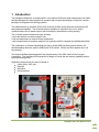
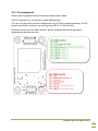
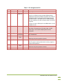
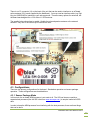
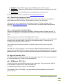
Navigation Board M3
User Manual
NavBoard M3 User Manual Rev B
Table of Contents
Contents
1.
Introduction ................................................................................................................................ 3
1.1
Limitations .......................................................................................................................... 4
1.1.1
Rate limits ..................................................................................................................... 4
1.1.2
Acceleration limits ......................................................................................................... 4
1.1.3
Magnetic field limits....................................................................................................... 4
1.1.4
GPS .............................................................................................................................. 4
1.1.5
Precautions and User Responsibility ............................................................................. 4
1.2
Theory of Operation ............................................................................................................ 5
1.2.1
Startup Conditions ........................................................................................................ 5
1.3
Modes of Operation ............................................................................................................ 6
2. Specifications and Characteristics .............................................................................................. 7
2.1
Performance Specifications – Inertial Sensors .................................................................... 7
2.2
Performance Specifications – Global Positioning Receiver ................................................. 7
2.3
Electrical Characteristics .................................................................................................... 8
2.4
Absolute Maximum Ratings ................................................................................................ 8
2.5
Mechanical and Pin Assignments ....................................................................................... 9
2.5.1
Dimensions ................................................................................................................... 9
2.5.2
Coordinate System and Orientation .............................................................................. 9
2.5.3
Pin Assignments ......................................................................................................... 10
3. Sensor Details and I2C addresses ........................................................................................... 13
3.1
GPS.................................................................................................................................. 13
3.2
Accelerometers................................................................................................................. 13
3.3
Rate Sensors .................................................................................................................... 13
3.4
Magnetometer .................................................................................................................. 13
3.5
ARM processor ................................................................................................................. 13
3.6
Planned Future Upgrades ................................................................................................. 14
4. Hardware Integration ................................................................................................................ 14
4.1
Power ............................................................................................................................... 14
4.1.1
Input Power ................................................................................................................ 14
4.2
GPS Antenna Options ...................................................................................................... 14
4.3
Configurations .................................................................................................................. 15
4.3.1
Sensor Package Mode ................................................................................................ 15
4.3.2
Stand Alone Operational Mode ................................................................................... 16
4.4
Special Interface Pins ....................................................................................................... 16
4.4.1
ARM Reset – SV1, Pin 3 ............................................................................................. 16
4.4.2
ARM Boot load – SV1, Pin 4 ....................................................................................... 17
5. Software Interface .................................................................................................................... 18
5.1
Firmware Upload Procedure ............................................................................................. 18
5.2
Serial Port via USB ........................................................................................................... 18
5.3
Recommended tools ......................................................................................................... 18
5.4
Native Software Description.............................................................................................. 18
5.5
Native Software Input ....................................................................................................... 18
5.6
Native Software Output..................................................................................................... 19
NavBoard M3 User Manual Rev B
Release Notes
Title
Subtitle
Type
Document number
Revision Index
Initial Release
A
B
NavBoard M3
NavBoard M3 User
Manual
Manual
UM2000
Date
9/2010
10/2010
8/2011
Name
MR
MR
MR
Status / Comments
Initial release
Software instructions / information added
Test software output example
IMPORTANT DISCLAIMERS
This document and the use of any information contained therein, is subject to the acceptance of the Ryan Mechatronics terms and
conditions. They can be downloaded from www.ryanmechatronics.com.
Ryan Mechatronics LLC makes no warranties based on the accuracy or completeness of the contents of this document and reserves the
right to make changes to specifications and product descriptions at any time without notice.
Ryan Mechatronics LLC assumes no liability for damages or otherwise due to use of the information in this document or application of any
device described in this document.
Ryan Mechatronics LLC stresses end user compliance with all applicable laws and regulations when using devices of this nature. Use by
an end user in violation of any applicable laws is automatic basis for termination of warranty, technical support and future sales.
Ryan Mechatronics LLC reserves all rights to this document and the information contained herein. Reproduction, use or disclosure to third
parties without express permission is strictly prohibited.
Copyright © 2011, Ryan Mechatronics LLC
NavBoard M3 User Manual Rev B
1. Introduction
The Navigation Board M3, or NavBoard M3, is a miniature GPS and inertial measurement unit (IMU)
package designed for either stand alone operation with on board processing or simply as a sensor
package for integration into existing systems.
The NavBoard has an excellent GPS module on board (U-Blox series) with both on board and off
board antenna capability. The off board antenna capability is important if the unit is used in
conditions where the on board antenna will be blocked by enclosures or other jamming.
The on board inertial measurement suite includes:
3 axis rate sensors to measure angular rate
3 axis accelerometers to measure linear acceleration
3 axis magnetometer to measure magnetic flux (typically used for compass type heading derivation)
The combination of all these capabilities with the on board ARM processing power allows a full
attitude heading reference system (AHRS) with GPS position, velocity and time updates all in one
tiny package.
The original NavBoard was designed to be complimentary to the SRV robot built by Surveyor
Corporation. The NavBoard M3 augments this design to include the rate sensing capability and on
board processing power.
Application areas include, but are not limited to:
UAVs (AUVs, UAS, etc)
Robotics
Education
Rocket science
NavBoard M3 User Manual Rev B
3
1.1 Limitations
The unit, like any IMU / AHRS, can be pushed beyond the limits of its ability to sense any of the
measurements it needs to operate correctly. The following list includes results that are known to
occur if operation exceeds the limits listed later in this document.
1.1.1 Rate limits
Saturation of maximum rate in any axis for any amount of time will result in an incorrect attitude
estimate if an attitude estimator has been hosted on the ARM processor. The longer the saturation
duration, the more error will be present in the attitude determination. A good attitude estimator shall
recover once saturation has stopped and the internal filter has time to reconverge on the correct
solution.
Please note: The NavBoard M3 does NOT ship with an attitude estimator set of code, but it has the
processing and code memory to host an estimator of the customers design.
1.1.2 Acceleration limits
Excessive acceleration can include acceleration above the rated levels in continuous application
(static / low frequency g’s), more elusive vibration (sinusoidal / random) or shock (impulse / random)
events that may not show full saturation of the accelerometers in data output, but have affected the
sensors internally and corrupted the values. Continued acceleration above the limits or excessive
vibration / shock events can corrupt the output acceleration.
1.1.3 Magnetic field limits
Magnetometers are sensitive to hard and soft iron effects, as well as induced magnetic fields from
high current. Saturation of the local magnetic field is easily identified, but lower level influence on
the sensor can result in pervasive errors as well. Calibration of the unit in the final configuration will
help prevent errors introduced by hard iron in the local area. However, induced magnetic fields from
high current devices or high power RF circuitry can result in operational errors. After a proper
calibration, no axis should exceed a +/- 1 gauss value.
1.1.4 GPS
GPS is a phenomenal technology allowing location of your position on the planet Earth within about
a 15 foot (5 meter) accuracy using a module the size of your thumb!
GPS is subject to many possible interference sources, including anything in the GPS frequency band
(including harmonics of lower frequencies from digital systems) and other jamming sources, like
foliage or direct blockage of the antenna.
This manual cannot begin to educate the user on limits of GPS technology, but we recommend both
Wikipedia and the support area on the U-blox (www.ublox.com) website for more information.
1.1.5 Precautions and User Responsibility
The NavBoard is an open electrical device with no case. It has no on board protection from short
circuits or accidental electrical damage. No system is fool proof, and all correct use and planning for
events in case of failure are the responsibility of the user.
Ryan Mechatronics cannot be held responsible for accidental or intentional damage caused
by this unit either directly or indirectly.
NavBoard M3 User Manual Rev B
4
1.2 Theory of Operation
The NavBoard is an integrated set of MEMS sensors and GPS that can be managed via an onboard
CPU to provide position, velocity, attitude and heading information, along with raw sensor data and
other useful information.
The on-board ARM processor can be reprogrammed easily by dragging valid object / bin files into a
Windows recognized USB flash drive.
However, the system is designed also to act as a standalone sensor package for use with any host
processor. A top level view of the usage modes is shown in the following figure.
1.2.1 Startup Conditions
The startup conditions of the pins on the NavBoard dictate what mode the system enters.
On Board ARM CPU running user code: For operation in standalone mode, user must have code
loaded and running on the processor. One code example would use the SP pin on the Host
connector (SV2). If that pin is jumped to ground upon boot, then the user code on the ARM
processor could look for this condition and decide to run user code or revert to sensor package only
operation.
NavBoard M3 User Manual Rev B
5
Reprogramming: For operation as a USB drive (allowing easy reprogramming via a drag and drop
of a .bin file to the drive), the system should be powered via USB first. If not recognized as a USB
drive, then the B pin on the SV1 connector can be momentarily grounded and then released. A
Windows system should recognize it as a USB flash drive. Note that this can take 45 to 60 seconds
for flash drive initialization.
Sensor Package Only: For operation as a sensor package only (i.e. for use with the SRV robot
from Surveyor), the only connections to the unit should be 3.3V, GND, SDA, and SCL. In this
condition, no on board ARM processing should occur (provided the user has not overridden this with
other software).
1.3 Modes of Operation
The NavBoard has been designed to be simple and effective at providing software flexibility and
standalone sensor capability. Specific pins and mode operations are shown below.
Power Supply - USB, 5V or 3.3V
ARM User Code
USB as
serial com
TTL serial
com out
ARM Reprogramming
USB Flash
drive drag
and drop
Serial
port
No user
code
Sensor
package
for
external
CPU
NavBoard M3 User Manual Rev B
6
2. Specifications and Characteristics
Presented in this section are the sensor and system specifications for the NavBoard. All parameters
specified are @ VDD = 3.3 V and Ta = 25°C.
2.1 Performance Specifications – Inertial Sensors
Characteristics
Conditions
Min
Typical
Max
Units
Angular Rate
Range
All axes
±2000
° / sec
Rate noise density
All axes
0.03
° /sec /
Bandwidth
Maximum, all axes
256
Hz
Sensitivity
All axes
14.375
LSB per
° / sec
Acceleration
±2
±2
±6
g
Range
All axes
Sensitivity
All axes
1024
LSB /g @ 2g
Sensitivity
All axes
340
LSB /g @ 6g
Bandwidth
All axes
Hz
Resolution
All axes
Output
data rate
/4
1
mg
Range
All axes
±1
Gauss
Bandwidth
All
10,000
Resolution
All
7
Magnetic Flux
milligauss
Specifications are subject to change at any time without notice
2.2 Performance Specifications – Global Positioning Receiver
Characteristics
Conditions
Min
Typical
2
29
29
<1
<2.5
<2.0
2
Max
Units
Position, Velocity and Time
Time to First Fix
Horizontal position
accuracy
Max Navigation
Update Rate
Velocity accuracy
External antenna
power supply
Cold Start
Warm Start
Hot Start
Without SBAS
SBAS
Message dependent
Center feed on external antenna
connection
s
m
4
Hz
0.1
m/s
3.3
V
Specifications are subject to change at any time without notice
NavBoard M3 User Manual Rev B
7
2.3 Electrical Characteristics
Characteristics
Conditions
Min
Typical
Max
Units
3.1
3.3
3.3
V
Power
3.3V Input Supply
Voltage Range
Vdd
Referenced to GND
NOTE: ONLY 3.3V or 5V supply
should be applied. Damage can result if
both supplies are active
5V Input Supply
Voltage Range
Note 5V external supply and USB 5V
input supply are common
4.65
5.0
5.1
Current
Average, measured at 3.3V
100
125
170
mA
GPS and sensors require minimum 100
mA. Remaining power draw dependent
on user code (if any)
Specifications are subject to change at any time without notice
2.4 Absolute Maximum Ratings
Parameter
Rating
Acceleration (any axis, 0.5 ms)
Unpowered
Vdd
2000g
Output Short-Circuit Duration
(Any Pin to Common)
Operating Temperature Range
TBD
Storage Temperature Range
-40°C to +125°C
-0.3V to +7V
-30°C to +85°C
Specifications are subject to change at any time without notice
Stresses above those listed under the Absolute Maximum Ratings may cause permanent damage to
the device. This is a stress rating only; functional operation of the device at or near these or any
other conditions above those indicated in the operational section of this specification is not implied.
Exposure to absolute maximum rating conditions for extended periods of time may affect device
reliability.
Drops onto hard surfaces can cause shocks of greater than 2000 g and can exceed the absolute
maximum rating of the device. Exercise care during handling to avoid damage.
NavBoard M3 User Manual Rev B
8
2.5 Mechanical and Pin Assignments
2.5.1 Dimensions
Dimensions for the unit are shown below. All units are in inches.
2.5.2 Coordinate System and Orientation
The NavBoard recently upgraded with a 3 axis MEMS rate sensor. Unfortunately, due to space
constraints, it needed to be placed on the bottom of the board. This makes its coordinate system
inconsistent with the other sensors and users should be aware of this when using it.
For the accelerometers and magnetometers: The orientation shown (X/Y/Z) frame is the local
body frame, with +Z following the right hand rule and coming up out the top of the board. Each of
these sensor packages is oriented to this frame.
For the rate sensors: The noted gyro orientation shown in the previous picture gyro has +Z
following the right hand rule and oriented down thru the board.
NavBoard M3 User Manual Rev B
9
2.5.3 Pin Assignments
Shown below is a graphic of the two connectors and pin names / labels.
The SV1 connector is for use with the on board ARM processor.
If you are using the device in sensor package mode (only I2C with a separate processor), the SV3
connector has all the connections you need (typically GND, 3.3V, SDA and SCL).
Not shown is a pin out for the USB connector, which is described later and can be used for
reprogramming and as a serial port.
NavBoard M3 User Manual Rev B
10
Table 1 - Pin Assignments SV1
Pin #
Pin Label
GND
Pin
Name
Ground
1
2
I/O
Description
N/A
System ground
5V
5V
N/A
5V external power.
WARNING: This power pin is common with USB 5V power
and there is no protection. Overvoltage or shorting this pin
while it is connected to your computer can damage your
computer.
If using USB power, do not connect this pin to anything.
Use either 3.3V power input, 5V power input, or USB
power input. Do not have multiple power sources
connected.
3
R
4
B
5
TX
6
RX
7
P8
8
P9
9
A0
10
A1
ARM
reset
ARM
boot
load
I
Resets on board ARM processor when grounded.
I
ARM
Serial
TX
O
Forces ARM to enter boot load (programming) mode based
on the following conditions:
1) USB power plugged in – momentarily shorting this
pin to ground will make the ARM processor be
discovered by Windows operating systems as a
flash drive. New firmware can be loaded by
dragging and dropping the firmware into this folder,
then resetting the unit
2) No USB power – Holding this pin low during power
application will force the ARM processor into ISP
programming mode via its serial port. FlashMagic
or other tool is needed to upload software in this
manner.
ARM Serial Port TX
ARM
Serial
RX
ARM
P1_9
ARM
P1_10
ARM
P0_11
ARM
P1_0
I
3.3V level
Pin 1.7 on processor, can be re-dedicated
ARM Serial Port RX
I/O
Pin 1.6 on processor, can be re-dedicated
ARM pin 1.9 GPIO
I/O
ARM pin 1.10 GPIO
I/O
ARM pin 0.11, can be configured as analog to digital
converter
ARM pin 1.0, can be configured as analog to digital
converter
I/O
For ARM pins, please see the LPC1343 User Manual from NXP for other pin options.
NavBoard M3 User Manual Rev B
11
Table 2 - Pin Assignments SV3
Pin #
Pin Label
Pin Name
I/O
Description
1
GND
Ground
N/A
System ground
2
SP
Enable
ARM Use
I/O
ARM pin 2.6.
This pin is a GPIO pin to the on board ARM processor.
Originally, this pin was intended (via specific user code) to
keep the processor in low power mode unless this pin is
grounded on boot. This allows use as a sensor package
and as a standalone unit with a simple jumper from this pin
to ground.
3
3.3V
3.3V
N/A
It is at its core just a GPIO pin for the ARM however, and is
available for use.
3.3V power input
Use either 3.3V power input, 5V power input, or USB
power input. Do not have multiple power sources
connected.
4
TP
5
SDA
6
RX
GPS
Timepulse
Serial
Data
GPS RX
O
I/O
1 PPS output pulse from GPS receiver, can be used to
sync external time
I2C SDA line
I
Board has 10k pull-up resistor on board
U-blox GPS receiver, 3.3V level RX serial port
7
SCL
Serial
Clock
O
With TX, can be used in parallel with U-center program to
monitor GPS operations
I2C SCL line
8
TX
GPS TX
O
Board has 10k pull-up resistor on board
U-blox GPS receiver, 3.3V level TX serial port
NavBoard M3 User Manual Rev B
12
3. Sensor Details and I2C addresses
Presented in this section are the references for all sensors and the processor on the board.
Answers to questions regarding the sensor details can be found in these data sheets and manuals.
Each device connected to an I2C bus is identified by a unique 7-bit address (whether it’s a
microcontroller, EEPROM, etc) and can operate as either a transmitter or receiver, depending on the
function of the device. The I2C addresses are provided here as well.
3.1 GPS
The GPS unit is a U-Blox receiver, the type easily seen on the chip itself. Details can be found at
www.u-blox.com.
The default I2C address for u-blox GPS receivers is set to 0x42. The 7-bit address for this device is
0x42. The 8-bit read address is 0x85. The 8-bit write address is 0x84.
Warning: U-Blox receivers act as a master I2C device 0.1 seconds after boot up. During this time, it
will query for external flash memory at address 0xA0. If you have any devices on your bus with this
address, you may experience issues with operation of the GPS. We recommend, if this is the case,
to disable the device at 0xA0 until 150 msec after boot to prevent any issues. None of the chips on
the NavBoard have this address, it would only be important for custom user designs.
3.2 Accelerometers
The 3 axis accelerometer is the LIS3LV02DQ unit from STMicroelectronics. Details can be found at
http://www.st.com/stonline/products/literature/ds/11115.htm . The 7-bit address for this device is
0x1D. The 8-bit read address is 0x3B. The 8-bit write address is 0x3A.
See future upgrades for more information regarding coding for this device.
3.3 Rate Sensors
The 3 axis rate sensor is the ITG-3200 from Invensense. Details can be found at
http://invensense.com/mems/gyro/itg3200.html. The 7-bit address for this device is 0x68. The 8-bit
read address is 0xD1. The 8-bit write address is 0xD0.
3.4 Magnetometer
The 3 axis magnetometer is from Honeywell, model HMC5843. Details can be found at
www.magneticsensors.com/datasheets/HMC5843.pdf. The 7-bit address for this device is 0x1E.
The 8-bit read address is 0x3D. The 8-bit write address is 0x3C.
3.5 ARM processor
The ARM processor is an LPC 1343. Software programming examples can be found at
www.nxp.com , http://ics.nxp.com/microcontrollers/to/pip/LPC1311.html, and the datasheet is located
here: http://www.nxp.com/documents/data_sheet/LPC1311_13_42_43.pdf.
To enable I2C communication as a slave requires programming by the user, and the slave address
can be defined at that time.
NavBoard M3 User Manual Rev B
13
3.6 Planned Future Upgrades
The next version of the NavBoard will likely replace the magnetometers and accelerometers with a
combined device, the LSM303DLH from STMicroelectronics
(http://www.st.com/stonline/products/literature/ds/16941.pdf).
The magnetometer address and protocol remains the same for this device.
The protocol for the accelerometer will change by a minor amount and its address changes. The 7bit address for this device is 0x18. The 8-bit read address is 0x31. The 8-bit write address is 0x30.
Please write your code in a modular fashion to take advantage of this future upgrade.
4. Hardware Integration
Presented in this section are selected hardware interface comments to help ease integration of the
unit in the end user system.
Please note - the NavBoard is an open electrical device with no case. It has no on board protection
from short circuits or accidental electrical damage. No system is fool proof, and all correct use and
planning for events in case of failure are the responsibility of the user.
Ryan Mechatronics cannot be held responsible for accidental or intentional damage caused
by this unit either directly or indirectly.
4.1 Power
4.1.1 Input Power
The NavBoard core electronics all operate off of 3.3V. There are three methods for powering the
board however. 3.3V input, 5V input, or USB (5V) input.
If you have 3.3V available, the most efficient method is to supply the NavBoard via the 3.3V
connection on SV3. This is ideal for using the unit as a sensor package where a separate CPU is
being used to acquire and use the data via I2C.
The 5V input on SV1 is common to the USB power bus. If you provide 5V power to the board, the
onboard regulator will generate 3.3V output for the electronics.
Do NOT supply more than one power supply to the unit (i.e. 3.3V and 5V, or USB power and 5V).
This will ultimately lead to damage of the NavBoard or your PC.
Critical Warning: When using USB power, the bare circuit board is powered by your USB port.
Shorting the unit out or overvoltaging it can directly damage your PC. Take extra precaution when
using it directly interfaced to your PC.
4.2 GPS Antenna Options
The NavBoard has an on board passive antenna for GPS reception, but with a solder jumper and
user supplied antenna, allows an external antenna to be used instead.
NavBoard M3 User Manual Rev B
14
There is a u.FL connector (J1) on the back of the unit that can be used to interface to an off board
active antenna (3.3V power supplied by the NavBoard). You may need an interface cable (e.g. DigiKey p/n A36232-ND) to interface to your active antenna. There are many options for antennas, but
the board was designed for a 3.3V active L1 GPS antenna.
The graphic below shows how to enable / disable the onboard passive antenna or the external
antenna. Only one or the other may be used at one time.
4.3 Configurations
There are two primary configurations for the board. Standalone operation and sensor package
operation. These configurations are described here.
4.3.1 Sensor Package Mode
In this mode, the on board ARM processor is not used at all. The I2C bus lines are used by a
separate host processor (like the SRV robot from www.surveyor.com ) to acquire inertial and GPS
data.
In order to keep the ARM processor from interfering with the host processor, there are three things
that can be done:
NavBoard M3 User Manual Rev B
15
HW Option: Keep ARM in reset by tying the ARM reset pin on SV3 to ground
SW Option 1: Program the ARM processor with specific software preventing use of the I2C
bus
SW Option 2: Wipe the ARM processor by programming no firmware at all
Both software option builds are available from www.ryanmechatronics.com.
4.3.2 Stand Alone Operational Mode
In this mode, the on board ARM processor acts as the master on the I2C bus and manages all
inertial sensors and GPS acquisition. Output data can be seen on the serial ports.
In this mode, the user is responsible for the software on the unit. Software example code is
available at www.ryanmechatronics.com. Pre-built bin files to accomplish simple data acquisition
and output are provided there as well.
4.3.2.1 Communication in StandAlone Mode
There are two methods of communication available in StandAlone mode, USB serial port and TTL
serial port. User program on the ARM processor determines which communication protocol can be
used.
USB communication is accessed via the USB mini-B connector.
TTL serial (3.3V level) is accessed via the TX/RX pins on the SV1 connector only. Note that the SV3
connector, which has pins labeled TX and RX, is not the ARM serial port. Those pins are for
accessing the serial port on the GPS receiver.
These methods are enabled and controlled via software, and are not both active at one time
(currently).
The UART is a 3.3V level interface. The unit does not support hardware handshaking. Do NOT
interface with a standard RS-232 port, as the voltages on that port will damage the unit. An external
adapter that uses 3.3V to convert to RS-232 levels can be powered from the onboard 3.3V regulator.
4.4 Special Interface Pins
The NavBoard utilizes external pins to help with user programming of the unit (not necessary if used
as a sensor package only). These pins are described here.
4.4.1 ARM Reset – SV1, Pin 3
This pin will hold the on board ARM processor in reset if grounded. This guarantees the ARM will
not be operating f using the unit as a sensor package only.
It can also be momentarily grounded to reboot the ARM.
This reset pin is ONLY for the ARM. If any other sensors need to be restarted, you must cycle
power to the unit.
NavBoard M3 User Manual Rev B
16
4.4.2 ARM Boot load – SV1, Pin 4
The ARM processor was intended to host user code. There are two ways to download new code to
the processor. The first is via the USB port. The second is via the serial port. Reprogramming is
accomplished via an on board boot loader in the processor.
4.4.2.1 USB reprogramming
If USB power is being used (i.e. the unit is plugged into a PC), then momentarily shorting this pin to
ground will make the ARM processor be discovered by Windows operating systems as a flash drive.
New firmware can be loaded by dragging and dropping the firmware into this folder, then resetting
the unit.
4.4.2.2 Serial port reprogramming
If external power is used and USB is not connected, then the unit can be reprogrammed via the
serial port. Holding the ARM Boot load pin low during power application will force the ARM
processor into ISP programming mode via its serial port. Flash Magic or a similar tool is needed to
upload software in this manner.
NavBoard M3 User Manual Rev B
17
5. Software Interface
The NavBoard software and support GUI is open source and can be found at
www.ryanmechatronics.com.
5.1 Firmware Upload Procedure
The easiest method to upload new firmware to the ARM processor is via USB. Follow these simple
steps:
1) Short the “B” pin to Ground on SV1
2) Plug unit via USB into a PC running Windows (XP, Vista, 7)
3) Remove the shorting wire from step 1
4) Windows will recognize the unit as a flash drive. This may take 30 to 45 seconds the first
time.
5) Move the desired firmware to the flash drive from your PC (just drag and drop!).
a. The filename MUST be “firmware.bin”
6) When complete (a few seconds), close the flash drive folder. Disconnect and reconnect the
USB cable (or reset the processor by shorting the “R” pin to ground momentarily on SV1.
5.2 Serial Port via USB
If the firmware loaded supports USB serial com, Windows will identify the unit when plugged in as a
serial port, but you may need to point at the correct INF file so it can correctly recognize it. The INF
file for the LPC1343 processor to act as a serial port is named lpc134x-vcom.inf and is located here:
www.ryanmechatronics.com/public_files/software/NavBoardM3/lpc134x-vcom.inf
5.3 Recommended tools
We highly recommend using Rowley Crossworks (http://www.rowley.co.uk) Crossworks for ARM as
the tool for reprogramming the NavBoard. Rowley tools are very simple to use and based on the
GCC compiler chain.
We also recommend the tools and evaluation boards from microbuilder.eu
(http://www.microbuilder.eu/home.aspx). They have an excellent set of prototyping boards, tools
and advice. Much of the software package that has been used as one core for programming the
NavBoard can be found in their LPC 1343 reference design via open source license.
5.4 Native Software Description
The Nav Board can ship with or without native software. The native software code and a GUI
(including source) is located here:
http://code.google.com/p/navboard-m3/source/browse/#svn%2Ftrunk%2FGoogleHosted
The nav board operates at 115k baud (serial version) or any baud rate (USB version), 8 bits, 1 stop
bit, no polarity and no handshaking. The native software has three modes: BIT, ASCII output and
BINARY output.
5.5 Native Software Input
The Nav Board accepts ASCII characters to change mode:
NavBoard M3 User Manual Rev B
18
Table 3 – Mode Change Commands for Nav Board
ASCII
command
0
ASCII value
0x30
Resultant
Mode
ASCII
1
0x31
BINARY
2
0x32
BIT
Mode Description
Outputs ASCII (human text readable) GPS and sensor
data.
Outputs binary GPS and sensor data
Outputs summary text message showing status of GPS
and sensors
5.6 Native Software Output
The Nav Board outputs the following message content per mode.
NavBoard M3 User Manual Rev B
19
Table 4 – Output Data for Nav Board
Mode
ASCII
Output Description
String output has the following fields:
G, GPS fix, Number of GPS sats in track, UTC, Latitude, Longitude, altitude
A, 99, AccX raw counts, AccY raw counts, AccZ raw counts
R, temperature, RateX raw counts, Rate Y raw counts, Rate Z raw counts
M, 99, MagX raw counts, MagY raw counts, MagZ raw counts
I,GPIO0,GPIO1,GPIO2,GPIO3,GPIO4,GPIO5,GPIO6
V,ADC 0 counts, ADC 1 counts
Scaling of raw counts to useful numbers is left to the user, but the following applies:
Accelerometer: Accel (m/s^2) = raw counts / 1024.0 * 9.8
Rate sensor temperature: data->temp = 35.0 + ((raw_temp + 13200)/280.0);
//Gyro scaling: 14.375 LSB/degrees/sec
Rate sensor scaling: rate (deg/s) = raw counts / 14.375
BINARY
Outputs binary GPS and sensor data, scaled in a binary format with the following
format:
mBinOut[0]=0xAE; //Header
mBinOut[1]=0xAE; //Repeated header
mBinOut[2] = (size of this array, typically 88 )
mBinOut[3-> 37] = GPS_Data //
mBinOut[38->50] = accelerometer data (m/s^2 units)
mBinOut[51->67] = temperature and gyro data (rad/s units)
mBinOut[68->80] = magnetometer data (gauss)
mBinOut[81->85] = ADC raw data
mBinOut[86->87] = GPIO
BIT
Outputs summary text message showing status of GPS and sensors
Ryan Mechatronics
----------------Nav Board M3 Built In Test
Acc: LSM303
Gyro: ITG-3200
Mag: HMC 5843
GPS: U-Blox
NavBoard M3 User Manual Rev B
20