1
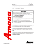
GUVA & GCVA
Two-Stage Variable Speed
High Efficiency Gas Furnace
®
User’s Information Manual
WARNING
If the information in these instructions is not followed exactly, a fire or
explosion may result causing property damage, personal injury or loss of
life.
– Do not store or use gasoline or other flammable vapors and liquids in
the vicinity of this or any other appliance.
– WHAT TO DO IF YOU SMELL GAS:
•
Do not try to light any appliance.
•
Do not touch any electrical switch; do not use any phone in your
building.
•
Immediately call your gas supplier from a neighbor’s phone.
Follow the gas supplier’s instructions.
•
If you cannot reach your gas supplier, call the fire department.
– Installation and service must be performed by a qualified installer,
service agency or the gas supplier.
You have purchased a residential variable speed high-efficiency, gas furnace. It
is designed to heat your home efficiently and safely. It is also designed to interface with your cooling equipment to circulate conditioned air during cooling
operation.
Your furnace functions are regulated by an integrated control module which
responds to your home thermostat. This module controls all aspects of operation,
and is designed to assure efficiency, reliability, comfort, and safety.
The GUVA and GCVA furnaces have been designed with efficiency and flexibility
in mind. They are capable of operating on low stage or high stage, in accordance
with current heating requirements. It incorporates the usage of a variable speed
circulator blower to promote efficiency and provide gentle, quiet operation.
These furnaces can be installed in an upright (GUVA) or horizontal (GCVA)
position. It can use either indoor or outdoor air for combustion purposes. Use of
indoor air, referred to as non-direct vent (single pipe), requires only a flue pipe;
combustion air is drawn from indoors. Use of outdoor air, referred to as direct
vent (dual pipe), requires both a flue pipe and a combustion air intake pipe.
Heating & Air Conditioning
®
Part No. 10318823 Rev. 2 (1)
Printed in USA
January 2003
C om fort. Q uality. Tru st.
Contents
Important Note To The Owner .......................................................................... 3
Component Identification ....................................................................... 4
General Information ................................................................................ 5
Unit Location .................................................................................................... 5
Unit Installation ................................................................................................. 5
Clearances and Accessibility ............................................................................ 6
Air Requirements ............................................................................................. 6
Combustion Air (Non-Direct Vent/Single Pipe) ................................................. 6
Combustion Air (Direct Vent/Dual Pipes) .......................................................... 7
Flue Pipe and Condensate Drainage ............................................................... 7
Indoor Humidity .......................................................................................... 7
For Propane (LP) Gas Installations Only .......................................................... 8
Operating Your Furnace ......................................................................... 9
Furnace Operation ........................................................................................... 9
Thermostat Functions....................................................................................... 9
Dehumidistat .................................................................................................... 9
Integrated Control Module ....................................................................... 10
Gas Valve .................................................................................................. 10
Igniter ........................................................................................................ 10
Blowers .......................................................................................................... 10
Starting Your Furnace ..................................................................................... 10
Shutting Down Your Furnace .......................................................................... 10
Safety Circuits ....................................................................................... 11
Integrated Control Module .............................................................................. 11
Primary Limit .................................................................................................. 11
Auxiliary Limit(s) ............................................................................................. 11
Rollout Limit(s) ............................................................................................... 11
Pressure Switches ......................................................................................... 11
Flame Sensor ................................................................................................. 11
Resetting From Lockout ................................................................................. 11
Routine Maintenance ............................................................................ 12
Annual Inspection ........................................................................................... 12
Filters ........................................................................................................ 12
Filter Removal .......................................................................................... 12
Filter Cleaning and/or Replacement ....................................................... 13
Troubleshooting / Before You Request a Service Call ....................... 14
Safety Labels ......................................................................................... 16
For Additional Information ................................................................... 17
THE INSTALLATION AND SERVICING OF THIS EQUIPMENT MUST BE PERFORMED BY
QUALIFIED, EXPERIENCED TECHNICIANS ONLY.
Due to policy of continual product improvement, the right is reserved
to change specifications and design without notice.
RECOGNIZE THIS SYMBOL AS A SAFETY PRECAUTION.
2
WARNING
Should overheating occur, or the gas supply fail to shut off, shut off the manual gas valve to the furnace before
shutting off the electrical supply.
WARNING
To avoid death, personal injury or property damage, do not use this furnace if any part of the furnace has been under
water. Immediately call a qualified service technician to inspect the furnace and to replace any part of the control
system and any gas control having been under water.
Important Note To The Owner
It is important that you fill out the owner’s registration card and mail it today. This will assist us in contacting you
should any service or warranty information change in the future. When filling in the registration card, be sure to
include the Model, Manufacturing and Serial Numbers, plus the installation date. If the registration card cannot be
located, please call 1-877-254-4729 to register the furnace.
Your warranty certificate is also supplied with the unit. Read the warranty carefully and note what is covered. Keep
the warranty certificate in a safe place, so you can find it, if necessary.
Before using this manual, check the serial plate for proper model identification.
Installer - Affix this manual, the Installation Guide, and Specifications Sheet adjacent to the appliance.
Owner - Keep all product literature in a safe place for future reference.
ATTENTION INSTALLING PERSONNEL
As a professional installer you have an
obligation to know the product better than the
customer. This includes all safety precautions
and related items.
Remember, it is your responsibility to install the
product safely and to know it well enough to be
able to instruct a customer in its safe use.
Safety is a matter of common sense...a matter
of thinking before acting. Most dealers have a
list of specific good safety practices...follow
them.
Prior to actual installation, thoroughly familiarize
yourself with this Instruction Manual. Pay
special attention to all safety warnings. Often
during installation or repair it is possible to place
yourself in a position which is more hazardous
than when the unit is in operation.
The precautions listed in this Installation Manual
are intended as supplemental to existing
practices. However, if there is a direct conflict
between existing practices and the content of
this manual, the precautions listed here take
precedence.
Remember to leave this manual with the homeowner.
3
Component Identification
11
3
13
3
*
2
14
16
*
*
*
*
*
1
*
19
12
11
25
26
30
3
16
22
19
12
20
*
*
23
30
21
*
32
19
20
*
*
13
26
27
21
*
17
14
24
29
15
31
21
28
25
2 22
9
Upflow /Horizontal (GUVA Models)
1
2
3
4
5
6
7
8
9
10
11
12
13
14
15
16
17
18
10
28
15
24
17 18
3
23
19
33
18
20
21
32 33
20
27
34
4
31
5
9 10
7
8
7
6
4
1
Counterflow /Horizontal (GCVA Models)
19
20
21
22
23
24
25
Two-Stage Gas Valve
Gas Line Entrance (Alternate)
Pressure Switch(es)
Gas Manifold
Combustion Air Intake Connection
Hot Surface Igniter
Rollout Limit
Burners
Flame Sensor
Flue Pipe Connection
Flue Pipe
Combustion Air Intake (Alternate)
Primary Limit
Gas Line Entrance
Flue Pipe Connection (Alternate)
Rubber Elbow
Two-Speed Induced Draft Blower
Electrical Connection Inlets (Alternate)
26
27
28
29
30
31
32
33
34
4
Coil Front Cover Pressure Tap
Coil Front Cover Drain Port
Drain Line Penetrations
Drain Trap
Blower Door Interlock Switch
Inductor (Not All Models)
Two-Stage Integrated Control Module
(with fuse and diagnostic LED)
24 Volt Thermostat Connections
Transformer (40 VA)
ECM Variable Speed Circulator Blower
Bottom Return Filter Retainer
Auxiliary Limit
Junction Box
Electrical Connection Inlets
Coil Front Cover
Combustion Air Inlet Pipe
BLOWER COMPARTMENT
7
BURNER COMPARTMENT
8
7
*
BLOWER COMPARTMENT
6
*
BURNER COMPARTMENT
5
General Information
This furnace is built to provide many years of safe and dependable service, provided it is properly installed and
maintained. However, abuse and/or improper use can shorten the life of the furnace and create hazards for you, the
homeowner. Take time to familiarize yourself with the information concerning furnace installation, features, operation, and maintenance contained within this manual.
WARNING
This product contains or produces a chemical or chemicals which may cause serious illness or death and which
are known to the State of California to cause cancer, birth defects or other reproductive harm.
WARNING
To avoid possible equipment damage, personal injury, fire or death, the following instructions must be observed
regarding unit location, air requirements and operating procedures.
Unit Location
WARNING
1. The furnace area and the vicinity of any other gas appliances must be kept clear and free of combustible
materials, gasoline, and other flammable vapors and
liquids. Also, do not store or use flammable items
such as paint, varnish, or lacquer in the area.
To avoid personal injury or fire, minimum clearances
to combustible surfaces must be followed.
7. Make certain the required clearances for the furnace
are always maintained. These clearances are listed
on the furnace clearance label. If any question develops, contact the installer of the furnace, or another
qualified servicer.
2. Do not store or use chlorine or fluorine or corrosion
producing products (bleaches, cements, strippers,
aerosols) near the unit. They can corrode the heat
exchanger.
3. Do not use the furnace closet as storage for brooms,
mops, brushes and oily rags or cloths. The area must
be kept clear, clean and free of lint. Furnace must be
kept free and clear of exposed or loose insulation materials in the area of installation. Examine the furnace
area when the furnace or additional insulation is
added since some insulation materials may be combustible.
Unit Installation
Examine the furnace installation to determine the following:
1. The flue vent pipe is physically sound, sealed, and
well supported. The vent slopes upward to vent terminal so condensate drains back toward the furnace.
The vent shows no evidence of leaking or separation
at joints or fittings.
4. Make sure the furnace is always connected to an approved vent, in good condition, to carry combustion
products outdoors.
2. The return air duct connection is physically sound,
sealed to the furnace casing, and terminates outside
the space containing the furnace.
5. Familiarize yourself with the controls that shut off the
gas and electrical power to the furnace. If the furnace
is to be shut down at the end of the heating season,
turn off both the gas and electrical power. For safety,
always turn the gas and electrical power off before
performing service or maintenance on the furnace.
3. The physical support of the furnace is sound without
sagging, cracks, or gaps around the base so as to
provide a seal between the support and the base.
4. There are no obvious signs of deterioration of the
furnace.
6. Establish a regular maintenance schedule to insure
efficient and safe operation of the furnace. The furnace should be checked at the beginning of each
heating and cooling season by a qualified service
technician.
5. Check for proper burner flame performance. Flame
should extend directly outward from burners without,
curling, floating, or lifting off.
5
General Information
WARNING
Clearances and Accessibility
Installations must adhere to the clearances to combustible materials for which this furnace has been design
certified. The minimum clearance information for this furnace is provided on the unit’s clearance label. These
clearances must be permanently maintained. In addition
to the required clearances to combustible materials, a
36-inch minimum for clearance servicing must be available in front of the unit. Unit positioning is referenced as
follows:
Death or personal injury from asphyxiation can result
from exposure to carbon monoxide.
Carbon monoxide or “CO” is a colorless and odorless
gas produced when fuel is not burned completely or
when the flame does not receive sufficient oxygen.
Be aware of these air starvation signals which
indicate conditions that may result in carbon monoxide or that carbon monoxide may be present:
TOP
1. Headaches-Nausea-Dizziness, Flu-Like Symptoms.
TOP
SIDE
SIDE
2. Excessive humidity-heavily frosted windows or a
moist “clammy” feeling in the home.
SIDE
3. Smoke from a fireplace will not draw up the chimney.
4. Flue gases that will not draw up the appliance vent
pipe.
BOTTOM
BOTTOM
Upflow
Counterflow
Combustion Air (Non-Direct Vent/Single
Pipe)
Horizontal
Air Requirements
WARNING
WARNING
To avoid death, personal injury or property damage,
enough fresh air for proper combustion and
ventilation of flue gases must be provided to this
furnace. Most homes require outside air to be
supplied into the furnace area.
It is vitally important that the furnace have proper
venting. To prevent possible death or personal injury
due to asphyxiation, this furnace must never be
common vented with another gas fired appliance.
Any alteration to any venting system must be in
accordance with local and national codes, and the
manufacturer's instructions.
Improved construction and additional insulation in
homes have reduced the heat loss and made these
homes much tighter around doors and windows so that
air infiltration is minimal. This creates a problem to
supply ventilation and/or combustion air for gas fired or
other fuel burning appliances. Any use of appliances
that pull air out of the house (clothes dryers, exhaust
fans, fireplaces, water heaters, non-direct vent furnaces,
etc.) increases this problem and appliances could be
starving for air.
In non-direct vent installations (single pipe), the air for
combustion and ventilation can typically be obtained
from the surrounding unconfined space or louvered
closet door. Observe the following precautions concerning air availability:
• When a furnace is installed in a closet and the
closet door is louvered, DO NOT OBSTRUCT
LOUVERS. Louvers must be open and clear to
provide combustion air to the furnace.
If fuel-burning appliances are starved for air, the flue
gases which these appliances produce as they operate
may not vent outdoors properly, but remain in the home
instead. These flue gases may include carbon monoxide.
• When a furnace is installed in a confined space
within a home and the air for combustion and ventilation enters the space through ducts from the
outside, be sure to routinely check the entering
and outlet, grilled openings to verify that they are
always clear and clean.
6
General Information
• Do not partition off a small area around the furnace
utilizing a non-louvered door. This could obstruct
the combustion air from reaching the furnace.
Provisions must be made to drain condensate from the
furnace and protect the condensate drain trap and drain
lines from freezing conditions. The drain trap and drain
lines must be kept clear of blockage.
• Do not allow the furnace air intake (top or side) to
become blocked.
Indoor Humidity
Relative humidity is the amount of water vapor in the air
relative to the amount the air can hold at the same
temperature. Example: At 40% relative humidity, the air
could hold 2 1/2 times as much moisture (2.5 x 40 =
100%) before becoming saturated.
• The combustion and ventilation air must never
come from a corrosive atmosphere.
Combustion Air (Direct Vent/Dual Pipes)
The colder the air; the less moisture it can hold. As air is
warmed, its ability to hold moisture is increased.
WARNING
Example: A winter day, outdoor temperature 10°F, and
relative humidity of 70%. If that air enters a home and is
warmed to 72°F the relative humidity will drop to 6%
(very dry) if no more moisture is added.
It is vitally important that the furnace have proper
venting. To prevent possible death or personal injury
due to asphyxiation, this furnace must never be
common vented with another gas fired appliance.
Any alteration to any venting system must be in
accordance with local and national codes, and the
manufacturer's instructions.
Relative humidity is important to your health and home
as proper humidification helps reduce respiratory
difficulties and helps improve the indoor air quality.
A good relative humidity is one just high enough to
barely start condensation along the lower edges or
lower corners of the windows. More than that can be
damaging.
In direct vent installations (dual pipes), the air for combustion and ventilation is obtained from outdoors through
an air intake pipe. Observe the following precautions
concerning air availability:
Frequent fogging or excessive condensation on inside
windows indicates the indoor humidity level is too high
for outdoor weather conditions. Damage to the building
may result if the condition persists. (Condensation on
inside of storm windows indicates loose inside windows.
Adding weather-stripping to tighten inside windows
usually corrects this problem.)
• To ensure proper furnace operation, both the air
intake pipe and the flue pipe must never become
obstructed.
• The combustion and ventilation air must never
come from a corrosive atmosphere.
The following table shows the recommended maximum
indoor humidity in relationship to the outdoor temperatures.
Flue Pipe and Condensate Drainage
Outdoor
Humidity
Temperature Single -Paned Double-Paned
Glass
Glass
+30°F
30%
50%
+20°F
20%
40%
+10°F
15%
35%
0°F
10%
30%
-10°F
5%
25%
-20°F
5%
20%
-30°F
3%
18%
WARNING
To prevent possible death or personal injury due to
asphyxiation, this furnace must be Category IV
vented.
The venting of this furnace (Category IV venting) must
be both gas and water tight. For proper performance,
the size, length, number of elbows, and termination
must be in accordance with the specifications outlined in
the furnace installation guide. The flue system must
slope towards the furnace for proper condensate
drainage. The flue pipe and its termination must be kept
clear of blockage. For further information on Category
IV venting, refer to the installation instructions accompanying this product. If not included, ask your installing
dealer or distributor for this information.
Table 1
7
General Information
For Propane (LP) Gas Installations Only
For furnaces operating on propane gas, please review the following warnings before use.
WARNING
To avoid death, personal injury or property damage due to explosion or fire, install a gas detecting warning device.
Since the odorant in propane gas can be reduced by iron oxide (rust), a gas detecting warning device is the only
reliable method to detect propane gas leaks.
WARNING
If the gas furnace is installed in a basement, an excavated area or a confined space, it is strongly recommended
to contact a propane supplier to install a gas detecting warning device in case of a gas leak.
•
Since propane gas is heavier than air, any leaking gas can settle in any low areas or confined spaces.
•
Propane gas odorant may fade, making the gas undetectable except with a warning device.
WARNING
An undetected gas leak will create a danger of explosion or fire. If the presence of gas is suspected, follow the
instructions on the cover of this manual. Failure to do so could result in SERIOUS PERSONAL INJURY OR
DEATH.
8
Operating Your Furnace
Furnace Operation
Room Temperature
Thermostat
In the heating mode, gas is burned and the products of
combustion are drawn through a heat exchanger by an
induced draft blower. The flue gases are then exhausted from your home through a flue pipe system.
The furnace circulator blower passes indoor air over the
heat exchanger and then through the conditioned
space. The furnace heat exchanger is actually two
exchangers, a primary and a secondary, connected in
series. The primary heat exchanger is a tubular stainless steel design built for exceptional durability and
efficient heat transfer. The secondary heat exchanger,
sometimes referred to as a recuperator coil, is a stainless steel tube and aluminum fin arrangement designed
to remove the last remaining heat from the flue gases.
The amount of heat withdrawn from the flue gases is so
great that the gases are actually cooled to the point of
condensing. This furnace therefore produces condensate (water) which must be directed to a drain. Furnaces of this type are referred to as “condensing
furnaces”.
Cool/Heat
Temperature
Control Dials
Fan Switch
System
Switch
OFF
Fan
Switch
AUTO
COOL
AUTO
COOL
ON
HEAT
AUTO
HEAT
ON
OFF
ON
Action
None
System only cools, fan
cycles off and on.
System only cools, fan
runs all the time.
System only heats, fan
cycles off and on.
System only heats, fan
runs all the time.
No heating or cooling,
fan runs all the time.
Cool/Heat
Switch
Typical Thermostat
There are also thermostats which automatically switch
from heating to cooling mode and those with night setback capability. The night set-back, or multiple setback types allow for a different temperature at night or
during the day when no one is at home. Programmable
thermostats will allow for more control and tailoring of
the heating and cooling functions. The level of this
control will depend on the type of thermostat applied.
Thermostat Functions
Dehumidistat
This furnace requires a two-stage thermostat. (NOTE:
A single-stage thermostat can be used with this furnace;
however, true two-stage operation will not be achieved.)
A two-stage thermostat will control the furnace firing rate
(low stage or high stage) depending on the difference
between the thermostat set point and the current room
temperature. A small temperature difference between
the set point and current room temperature will require a
low stage firing rate, while a large difference between
the two will require a high stage. BE SURE TO BECOME FAMILIAR WITH YOUR THERMOSTAT. Proper
use of the two-stage thermostat and furnace will maintain tighter temperature control than a conventional
single-stage system.
A dehumidistat is an accessory that controls excess
humidity within a home. This accessory allows homeowner selection of a desired relative humidity setting
similar to the selection of a desired temperature setting
on the thermostat. The dehumidistat must be used in
conjunction with a thermostat. The dehumidistat is not
included with this furnace; however, the GUVA/GCVA
furnace comes “dehumidistat-ready”.
WARNING
Electrical components are contained in both
compartments. To avoid electrical shock, injury or
death, do not remove any internal compartment
covers. Contact a qualified servicer at once if an
abnormal condition is noticed.
For optimal furnace operation, set the thermostat to the
desired temperature. Do not “over adjust” the thermostat
to turn the heat on. Over adjusting will cause high stage
operation when low stage operation would have been
sufficient. An appropriately set thermostat will minimize
temperature fluctuations.
Notice:
The most widely used types of two stage thermostats
will control both heating and cooling functions and will
have a Fan Switch with AUTO and ON settings. On
AUTO, the circulating air blower will cycle on/off with the
furnace but if switched to ON it will run continuously
regardless of whether or not heating or cooling is being
provided.
Do not use this furnace if any part has been under
water. Immediately call a qualified servicer to inspect
the furnace and to replace any part of the control
system and any gas control which has been under
water.
Keep both doors in place except for inspection and
maintenance. An interlock switch prevents furnace
operation if the blower door is not in place.
9
Operating Your Furnace
Integrated Control Module
8. If you smell gas following the five minute waiting period in step 7, immediately follow the instructions on
the cover of this manual. If you do not smell gas after five minutes, move the furnace gas valve ON/
OFF switch to the ON position.
This furnace is equipped with an integrated control
module which regulates all furnace operations. The
control responds to input from the thermostat, initiates
and controls normal furnace operation, and monitors
and responds to all safety circuits.
9. Replace the burner compartment door.
Gas Valve
10. Open the external manual gas shut-off valve.
The gas valve regulates gas flow to the burners in
response to input from the integrated control module.
11. Turn on the electrical power to the furnace.
12. Adjust the thermostat to a setting above room temperature.
Igniter
The furnace has an electronic ignition device which
lights the burners automatically, never try to light the
burners by hand.
13. After the burners are lit, set the thermostat to desired
temperature.
Outlet (Manifold)
Pressure Tap
(Side of Valve)
Blowers
An induced draft blower is utilized to draw flue products
through the heat exchanger and exhaust them outdoors.
The circulator or main blower passes indoor air over the
heat exchanger and throughout the conditioned space.
Both blower motors are permanently lubricated, no
further oiling is required.
Gas Valve
Low Manifold
Regulator Adjustment ON/OFF Switch
Screw (Under Cap)
Inlet Pressure Tap
(Side of Valve)
Manometer
Hose
Starting Your Furnace
High Manifold
Regulator Adjustment
Screw (Under Cap)
WARNING
PERSONAL INJURY HAZARD
White-Rodgers
Model 36E54
(Right Side Up)
To avoid death, personal injury, or property damage,
do not remove any internal compartment covers.
Electrical components are contained in both
compartments. Contact a qualified servicer at once
if any abnormal condition is noticed.
Shutting Down Your Furnace
To shut down your furnace operation, follow the steps
listed below.
To put your furnace into operation, follow the steps
listed below.
1. Set the thermostat to the lowest setting.
2. Integrated control closes gas valve extinguishing
flame.
1. Close the external manual gas shut-off valve.
2. Turn off the electrical power to the furnace.
3. Induced draft blower is de-energized following a 15second delay. The circulator blower is de-energized
following a 60-, 90-, 120-, or 180-second delay period and a 30-second ramp down period.
3. Set the room thermostat to the lowest possible setting.
4. Remove the burner compartment door.
4. Remove the burner compartment door.
5. This furnace is equipped with an ignition device
which automatically lights the burner. Do not try to
light the burner by hand.
5. Move the furnace gas valve ON/OFF switch to the
OFF position.
6. Move the furnace gas valve ON/OFF switch to the
OFF position.
6. Turn OFF all electrical power to the furnace if service
is to be performed.
7. Wait five minutes to clear out any gas. Then smell
for gas, including near the floor as some types of gas
are heavier than air.
7. Close the external manual gas shut-off valve.
8. Replace the burner compartment door.
10
Safety Circuits
A number of safety circuits are employed to ensure safe and proper furnace operation. These circuits serve to
control any potential safety hazards and, as inputs in the monitoring and diagnosis of abnormal function. These
circuits are continuously monitored by the integrated control module.
Integrated Control Module
ROLLOUT
LIMIT(S)
The integrated control module is an electronic device
which regulates all furnace operations. Responding to
the thermostat, the module initiates and controls normal
furnace operation, and monitors and addresses all
safety circuits. If a potential safety concern is detected,
the module will take the necessary precautions and
provide diagnostic information through an LED located
on the module. See troubleshooting chart on page 14.
PRIMARY LIMIT
FLAME SENSOR
PRESSURE
SWITCH
PRESSURE
SWITCH
Primary Limit
BLOWER
DECK
The primary limit control is located on the partition panel
and monitors heat exchanger compartment temperatures. It is a normally closed (electrically), automatic reset, temperature activated sensor. This limit guards
against overheating as a result of insufficient conditioned
air passing over the heat exchanger.
CIRCULATOR
BLOWER
Auxiliary Limit(s)
AUXILIARY LIMIT
(UPFLOWS)
AUXILIARY LIMIT
(COUNTERFLOWS)
Safety Circuits
Upflow Shown
(Counterflow Similar)
The auxiliary limit control is located on or near the blower
deck and monitors heat exchanger compartment temperatures. It is a normally closed (electrically), manual
reset, temperature activated sensor. This limit guards
against overheating as a result of insufficient conditioned
air passing over the heat exchanger.
Resetting From Lockout
Furnace lockout is characterized by a non-functioning
furnace (circulator blower may be running continuously)
providing a one flash diagnostic LED code. Lockout
results when a furnace is unable to achieve ignition after
three attempts, or when it has lost flame five times
during a single call for heat. If the furnace is in “lockout”, it may be reset by any of the following methods:
Rollout Limit(s)
The rollout limit is a normally-closed (electrically),
manual-reset, temperature-activated sensor. It is
mounted on the burner/manifold assembly and monitors
the burner flame. If there is an improper draw of burner
flames into the heat exchanger, the rollout limit will detect
it and shutdown gas flowing to the burners.
1. One-hour automatic reset. Control will automatically
reset itself and attempt to resume normal operations
following a one hour lockout period.
2. Power interruption. Interrupt 115 volt power to the
furnace for between 0 and 20 seconds.
Pressure Switches
The pressure switches are normally-open (closed during
operation), single-pole single-throw, negative air pressure activated switches. They monitor the airflow (combustion air and flue products) through the heat
exchanger via pressure taps located on the induced draft
blower and the coil front cover. These switches guard
against insufficient airflow (combustion air and flue products) through the heat exchanger and blocked condensate drain conditions.
3. Thermostat cycle. Interrupt thermostat signal to the
furnace for between 0 and 20 seconds.
If the condition which originally caused the lockout still
exists, the control will return to lockout. Refer to the
“Troubleshooting” section for aid in determining the
cause. If your furnace frequently locks out, a problem
exists which must be corrected. Contact a qualified
servicer.
Flame Sensor
The flame sensor is a probe mounted to the burner/manifold assembly which uses the principle of flame rectification to determine the presence or absence of flame.
11
Routine Maintenance
If you perform maintenance on the furnace yourself, remember that certain mechanical and electrical knowledge,
skills and tools are required to perform maintenance on the furnace. Personal injury or death my result. If you are
not properly trained. You should call your installing dealer or place of purchase if you are uncertain about your ability
to perform maintenance.
WARNING
To avoid death or personal injury due to electrical shock, disconnect the electrical power before performing any
maintenance.
Annual Inspection
Filters
The furnace should be inspected by a qualified installer,
or service agency at least once per year. This check
should be performed at the beginning of the heating
season. This will insure that all furnace components are
in proper working order and that the heating system
functions appropriately. Particular attention should be
paid to the following items. Repair as necessary.
WARNING
To avoid death, personal injury or property damage,
disconnect electrical power before removing filters.
Never operate furnace without a filter installed. Dust
and lint will build up on internal parts resulting in
loss of efficiency, equipment damage and possible
fire.
• Flue pipe system. Check for blockage and/or leakage. Check the outside termination and the connections at and internal to the furnace.
• Combustion air intake pipe system (where applicable). Check for blockage and/or leakage.
Check the outside termination and the connection
at the furnace.
A return air filter is not supplied with this furnace;
however, a means of filtering all of the return air must
be provided. Your installer will supply filters at the time
of installation. Become familiar with filter location and
procedures for removing, cleaning and replacing them.
• Heat exchanger. Check for corrosion and/or
buildup within the heat exchanger passageways.
If you need assistance, contact the installer of your
furnace or another qualified servicer.
• Burners. Check for proper ignition, burner flame,
and flame sense. Flames should extend directly
outward from burners without curling, floating or
lifting off.
Filters must be inspected, cleaned or changed every
two months or as required. As a homeowner, it is your
personal responsibility to keep air filters clean. Remember that dirty filters are the most common cause of
inadequate heating or cooling performance.
• Drainage system. Check for blockage and/or leakage. Check hose connections at furnace.
• Wiring. Check electrical connections for tightness
and/or corrosion. Check wires for damage.
Filter Removal
Filters are located either at the unit or in a central return
grille. Horizontal installations use a ductwork or central
return grille location. If a filter is located at the unit, use
the following information to aid in filter removal.
• Filters. Check that filters are clean and in the
proper placement in the furnace or duct system.
Upflow Filters (Upright)
To remove a filter from the bottom of the blower compartment:
1. Turn OFF electrical power to furnace.
2. Remove blower compartment door.
Check the burner flames for:
1. Good adjustment
2. Stable, soft and blue
3. Not curling, floating, or lifting off.
3. Push back and up on the wire filter retainer to release it from under the front lip of the furnace
basepan.
4. Slide filter forward and out.
5. Replace filter by reversing the procedure for removal.
Burner Flame
To remove filters from an external filter rack in an
upright upflow installation, follow the directions provided
with the external filter rack kit.
12
Routine Maintenance
To remove internal filter(s) from the retaining rails on the
side(s) of the blower compartment in an upright installation:
If using Media Air Cleaner MAC1 or Electronic Air
Cleaner EAC5, follow the directions provided with the
air cleaner for proper filter removal, cleaning, and
replacement.
1. Turn OFF electrical power to furnace.
2. Remove the blower compartment door.
Counterflow Filters (Upright)
To remove filters from the ductwork above an upright
counterflow installation:
3. Grasp the lower portion of the filter and lift up.
4. Angle the filter towards the blower until the filter is
clear of the bottom rail.
1. Turn off electrical power to furnace.
2. Remove access door provided in the ductwork
above the furnace.
5. Lower the filter down and pull outward.
6. Replace the filter by reversing the procedure for removal.
3. Remove filters from the ductwork.
4. Replace filters opposite of removal. Replace access
door.
Front of Furnace
Front of Furnace
Blower
Blower
Horizontal and Central Return Filters
To remove filter(s) from ductwork or central return grille
installation:
1. Turn off electrical power to the furnace.
Filter
2. Remove filter(s) from ductwork or central grille location.
3. Replace filter(s) opposite removal.
Grab Here
And Lift
Filter Cleaning and/or Replacement
Use a vacuum cleaner to clean out the blower compartment and the adjacent area of the return air duct
a. Lift filter above bottom b. Tilt filter to clear rail.
rail
Front of Furnace
Front of Furnace
Blower
Blower
Disposable filters must be replaced with a filter or filters
of the same size as that which is removed. Filters must
comply with UL900 or CAN/ULC-S111 Standards.
Permanent filters must be cleaned, washed, and dried
as specified by the filter manufacturer. Filters which use
a dust adhesive should be sprayed or oiled as recommended by the filter and adhesive manufacturers. If it
becomes necessary to replace a permanent filter, it
must be replaced with a filter or filters of the same size
as that which is removed. Filters must comply with
UL900 or CAN/ULC-S111 Standards.
When reinstalling filters, be careful to maintain correct
airflow direction.
c. Lower filter below top
rail.
d. Slide filter out.
Filter Removal Procedure
13
Troubleshooting / Before You Request a Service Call
If your furnace is not operating or is performing improperly, take time to perform the following checks before requesting service. A couple of simple checks may allow you to avoid a service call. If the following steps do not resolve
the problem, contact a qualified servicer for further troubleshooting and/or repairs. Do not attempt troubleshooting
beyond that which is outlined below. Do not attempt repairs yourself. Use the diagram on page 4 for parts reference.
If your furnace will not start, check the following (in sequence):
NOTE: If flashing, the integrated control module diagnostic LED flash code must be recorded prior to turning off the
power to the furnace or opening the blower compartment door. To determine the flash code, count the number of
flashes seen through the blower compartment door sight glass. Refer to the diagnostics chart for a description of the
LED flash codes and their possible causes.
•
•
•
•
Check thermostat for proper operation. Verify that it is set on HEAT and that temperature setting is above
room temperature.
Check to see that the electrical disconnect at the furnace location is in the ON position. If the switch is in the
OFF position, switch it to the ON position to supply electrical power to the furnace.
Check fuse or circuit breaker in furnace electrical circuit. Replace as necessary.
Check to see that the manual gas shut-off valve external to the furnace is in the ON position. If the valve is in
the OFF position, turn the gas ON following the start up procedures outlined in the “Starting Your Furnace”
section.
NOTE: If flashing, record the integrated control module diagnostic LED flash code prior to power interruption. Turn
off furnace electrical power prior to proceeding.
•
•
•
•
Remove burner compartment door and check to see that gas valve ON/OFF switch is in the ON position. (See
figure on page 10) If the switch is in the OFF position, turn the gas ON following the start up procedures
outlined in the “Starting Your Furnace” section.
Remove blower compartment door and check to verify whether or not the manual reset auxiliary limit control
has tripped. The auxiliary limit control is located on the circulator blower. (See figure on page 4) If the auxiliary limit control has tripped, a reset “click” will be heard when the red button on the back of the control is
pressed. Replace door. NOTE: Do not reset the auxiliary limit control more than once. If the control trips
again, follow the furnace shut down procedure outlined in the “Starting Your Furnace” section and contact a
qualified servicer.
Check for blockage at the termination(s) of flue pipe (and the combustion air intake pipe where present). Also
check for blockage in the drain trap. Clear if possible. (See figure on page 4)
Check for blockage in the drain lines. If blockage is present, please contact a qualified servicer.
If you experience insufficient airflow, check the following (in sequence):
•
Check for dirty filter(s). This is the most common cause of improper furnace operation. Replace or clean
filters as necessary.
•
Check for blocked return air or supply air grilles throughout your home. Grilles may be blocked by furniture,
14
Troubleshooting / Before You Request a Service Call
Symptoms of Abnormal
Operation
- Furnace fails to operate.
and
- Integrated control module diagnostic
LED provides no signal.
- Furnace fails to operate.
and
- Integrated control module diagnostic
LED is lit continuously.
- Furnace is not operating
and
- Integrated control module diagnostic
LED is flashing one flash.
- Furnace fails to operate.
and
- Integrated control module diagnostic
LED is flashing two flashes.
- Induced draft blower runs continuously
with no further furnace operation.
and
- Integrated control module diagnostic
LED is flashing three flashes.
- Circulator blower runs continuously
with no further furnace operation.
and
- Integrated control module diagnostic
LED is flashing four flashes.
- Furnace fails to operate.
and
- Integrated control module diagnostic
LED is flashing six flashes.
- Normal furnace operation.
but
- Integrated control module diagnostic
LED is flashing seven flashes.
- Furnace is not operating.
and
- Integrated control module diagnostic
LED is flashing eight flashes.
- Furnace operating on low stage with
temperature of conditioned air lower than
typical.
and
- Integrated control module diagnostic
LED is flashing nine flashes.
- Induced draft and circulator blower run
continuously with no further
furnace operation.
and
- Integrated control module diagnostic
LED is flashing continuously.
Associated
LED Code
(See Notes 1 &
2)
Probable Cause(s)
Corrective Action
(See Notes 1 & 2)
None
- No electrical power to furnace.
- Confirm that the external electrical disconnect switch is in the "ON" position.
If "OFF", switch to the "ON" position.
- Check for tripped or blown circuit breaker or fuse. Replace if necessary.
ON
Continuous
On
1
1 Flash
- Integrated control module has an
internal fault.
- No gas supply to furnace.
- Condensate drain blocked.
(See Note 3)
2
- Have servicer inspect furnace and replace faulty integrated control module
if if necessary
necessary.
- Confirm that the external manual gas shut-off valve is in the "Open"
position.
position.
IfIf “Closed”,
when
"Closed",follow
followthe
thestart
startupupprocedure
procedureoutlined
outlinedininthis
thismanual
manual
when
moving
moving the
the gas
gas shut-off
shut-offvalve
valvetotothe
the“Open”
"Open"position.
position.
- Check drain
drain system
system for
for blockage.
blockage.
- Possible pressure switch malfunction.
- Have servicer inspect furnace and make necessary corrections.
- Blocked flue and/or inlet air pipe.
- Check flue and/or inlet air piping for blockage, especially at the outdoor
termination(s).
2 Flashes
3
1
3 Flashes
4
- Blocked drain system.
- Check drain system for blockage. Clear if possible.
- Check filters. Repace or clean if necessary.
- Dirty filters or blocked return grilles.
4 Flashes
6
6 Flashes
- Polarity of electrical power to furnace
or control module is reversed.
- Check for furniture, curtains, etc. blocking return grilles. Correct if
necessary.
- Have servicer inspect furnace and make necessary corrections.
- Poor unit ground.
- Flame sensor is coated/oxidized.
7
7 Flashes
8
8 Flashes
(See Note 4)
9
9 Flashes
(See Note 3)
C
- Flame sensor is incorrectly positioned
in burner flame
- Possible igniter or integrated control
module problem.
- Have servicer inspect furnace and make necessary corrections.
- Have servicer inspect furnace and make necessary corrections.
- Blocked flue and/or inlet air pipe.
- Check flue and/or air inlet piping for blockage, especially at the outdoor
termination(s).
- Malfunction in flame sense circuit.
- Have servicer inspect furnace and make necessary corrections.
Continuous
Flashing
1) LED flash code may be viewed through sight glass in blower compartment door.
2) LED flash code will cease if power to the control module is interrupted through the disconnect or furnace door switch.
3) Integrated control module will automatically attempt to reset from "lock out" (1 Flash) after one hour.
15
WARNING: IMPROPER INSTALLATION, ADJUSTMENT, ALTER-
ATION, SERVICE OR MAINTAINANCE CAN CAUSE PROPERTY
DAMAGE, PERSONAL INJURY OR LOSS OF LIFE, EXPOSURE
TO SUSTANCES IN FUEL OR FROM FUEL COMBUSTION WHICH
CAN CAUSE DEATH OR SERIOUS ILLNESS, AND WHICH ARE
KNOWN TO THE STATE OF CALIFORNIA TO CAUSE CANCER
BIRTH DEFECTS, OR OTHER REPRODUCTIVE HARM. REFER
TO THE USER'S INFORMATION MANUAL PROVIDED WITH
THIS FURNACE. INSTALLATION AND SERVICE MUST BE
PERFORMED BY A QUALIFIED INSTALLER, SERVICE
AGENCY OR THE GAS SUPPLIER.
DO NOT STORE OR USE GASOLINE OR OTHER
FLAMMABLE VAPORS AND LIQUIDS IN THE VICINITY
OF THIS OR ANY OTHER APPLIANCE.
FOR YOUR SAFETY
SEE INSIDE SURFACE OF LOUVERED DOOR FOR
LIGHTING/OPERATING INSTRUCTIONS.
16
TO TURN OFF GAS TO APPLIANCE
1. Set the thermostat to lowest setting.
2. Turn off all electric power to the appliance
if service is to be performed.
3. Push the gas control lever to "OFF" Position.
Do not force.
4. Replace control access panel.
LES INDICATIONS POUR L'ECLAIRAGE ET LE
SERVICE SE TROUVENT A LA SURFACE
INTERIEURE DU COMPARTMENT BRULEUR.
11072710
1. Régler le thermostat à la température la plus basse.
2. Couper l'alimentation électrique de l'appareil s'il
faut procéder à des opérations d'entretien.
3. Pousse le levier du contrôle du gaz à "OFF / ARRET"
position.
Ne pas forcer.
4. Remettre en place le panneau d'accès.
POUR COUPER L'ADMISSION
DE GAZ DE L'APPAREIL
1. ARRETÊR! Lisez les instructions de sécurité sur
la portion supérieure de cette étiquette.
. 2. Régler le thermostat à la température la plus basse
3. Couper l'alimentation électrique de l'appareil.
4. Cet appareil ménager étant doté d'un système
d'allumage automatique, ne pas essayer à
allumer le brûleur manuellement.
5. Pousse le levier du contrôle du gaz à "OFF/ ARRET"
position.
6. Attendre cinq (5) minutes pour laisser echapper tout le
gaz. Renifler tout autour de l'appareil, y compris près du
plancher, pour déceler une odeur de gaz. Si c'est le cas,
ARRETER! Passer à l'étape B des instructions de sécuritié
sur la portion supérieure de cette étiquette.
S'il n'y a pas d'odeur de gaz, passer à l'étape suivanté.
7. Pousse le levier du contrôle du gaz à "ON/MARCHE"
position.
8. Remettre en place le panneau d'accés.
9. Mettre l'appareil sous tension.
10. Régler le thermostat à la température desirée.
11. Si l'appareil ne se met pas en marche, suiyre les
instructions intitulées. Comment coupler l'admission
de gaz de l'appereil et appeler un technicien
qualifié ou le fourrnisseur de gaz.
MISE EN MARCHE
dans l'eau, complètement ou en partie. Appeler un
technicien qualifié pour inspecter l'appareil et
remplacer tout partie du système de contrôle et
toute commande qui ont été plongés dans l'eau.
D. Ne pas se servir de cet appareil s'il a été plongé
Ne pas tenter d'allumer l'appariel
Ne toucher aucun interrupteur électrique;
n'utiliser aucun téléphone dans le bâtiment.
Appeler immédiatement le fournisseur de gaz
en employant le téléphone dún voisin.
Respecter à la lettre les instructions du
fournisseur de gaz.
Si personne ne répond, appeler le service des
incendies.
C. Ne pousser ou tourner le levier d'admission du gaz
qu'à la main; ne jamais emploer d'outil à cet effet.
Si la manette reste coincée, ne pas tenter de la
réparer; appeler un technicien qualifié. Quiconque
tente de forcer la manette ou de la reparer peut
déclencher une explosion ou un incendie.
QUE FAIRE S'IL Y A UNE ODEUR DE GAZ
renifler tout autour de l'appariel pour déceler
une odeur de gaz. Renifler près du plancher, car
certains gaz sont plus lourds que l'air et
peuvent s'accumuler au niveau du so.l
T HIS C O M P A RT M E N T M U ST B E
1. STOP! Read the safety information above on
this label.
2. Set the thermostat to lowest setting.
3. Turn off all power to the appliance.
4. This appliance is equipped with an ignition.
device which automatically lights the burner.
Do not try to light the burner by hand.
5. Push the gas control lever to "OFF" Position.
Do not force.
6. Wait five (5) minutes to clear out any gas. Then
smell for gas, including near the floor. If you
then smell gas, STOP! Follow "B"
in the safety. information above
on this label if you don't smell
gas, go to next step.
7. Push gas control lever
to "ON".
8. Replace access panel.
9. Turn on all electric
power to the appliance.
10.Set thermostat to desired setting.
11.If the appliance will not operate,
follow the instructions "To Turn
Off Gas To Appliance" and call your
service technician or gas company.
Cet appareil ne comporte pas de veilleuse. Il est
muni d'un dispositif d'allumage qui allume
automatiquement le brûleur. Ne pas tenter
d'allumer le brûleur manuellement.
B. AVANT DE LE FAIRE FONCTIONNER,
A.
la lettre les instructions dans le présent manuel
risque de déclecher un incendie ou une explosion
entraînant des dammages matériels, des lésions
corporelles ou la perte de vies humaines.
LIRE AVANT DE METTRE
EN MARCHELIRE
AVERTISSEMENT: Quiconque ne respecte pas á
LO S ED E X CE P T W H EN
W A R N IN G : CS ER
V IC IN G
OPERATING INSTRUCTIONS
D. Do not use this appliance if any part has been underwater.
Immediately call a qualified service technician to inspect
the appliance and to replace any part of the control
system and any gas control which has been underwater.
C. Use only your hand to push in or turn the gas control lever.
Never use tools. If the lever will not push in or turn by
hand, don't try to repair it, call a qualified service
technician. Force or attempted repair may result in a fire
or explosion.
Do not try to light any appliance.
Do not touch any electric switch;
do not use any phone in your building.
Immediately call your gas supplier from a neighbor's
phone. Follow the gas supplier's instructions.
If you cannot reach your gas supplier,
call the fire department.
WHAT TO DO IF YOU SMELL GAS
B. BEFORE OPERATING smell all around the appliance
area for gas. Be sure to smell next to the floor
because some gas is heavier than air and will
settle on the floor.
A. This appliance does not have a pilot. It is equipped
with an ignition device which automatically lights
the burner. Do not try to light the burner by hand.
explosion may result causing property damage,
personal injury or loss of life.
FOR YOUR SAFETY
READ BEFORE OPERATING
WARNING: If you do not follow these instructions
Safety Labels
NOTE: If safety labels are missing or illegible, contact the installing dealer or our Customer Service Department for
ordering information.
B 1 3 5 8 0 -1 L A
A V E R TIS S E M E N T: F ER M E , S AU F P O U R L'EN TRE T IE N
C E CO M P AR T IM EN T D O IT RE S T ER
AVERTISSEMENT: UNE INSTALLATION, UN REGLAGE,
UNE MODIFICATION, UNE ENTRETIEN, OU UNE
MAINTAINANCE INCORRECTS PEUVENT ENTRAINER DES
DOMMAGES MATERIALS, DES LESIONS CORPORELLES OU LA
PERTE DE VIES HUMAINES. CONSULTER LE MANUEL DES
USAGER FOURNI AVEC CE GENERATEUR D'AIR CHAUD.
L'INSTALLATION ET L'ENTRETIEN DOIVENT ETRE
EFFECTUE'S PAR UN INSTALLATEUR QUALIFIE, UN
ORGANISME DE MAINTENANCE OU LE FOURNISSEUR DE GAZ.
NE PAS ENTREPOSER NI UTILISER DE L'ESSENCE
NI D'AUTRES VAPEURS OU LIQUIDES INFLAMMABLES
DANS LES VOISINAGES DE CET APPAREIL, NI DE
TOUT AUTRE APPAREIL.
AVERTISSEMENT
10232006
For Additional Information
Most questions can be answered by your local dealer. If you need further information regarding the operation,
maintenance, or service of your furnace, contact your dealer.
If you have other matters that cannot be resolved locally, or you need additional information regarding other heating
and cooling products offered by us - please call:
CONSUMER INFORMATION LINE
TOLL FREE
1-877-254-4729 (U.S. only)
email us at: [email protected]
fax us at: (731) 856-1821
(Not a technical assistance line for dealers.)
Outside the U.S., call 1-713-861-2500.
(Not a technical assistance line for dealers.)
Your telephone company will bill you for the call.
Ask a participating dealer about our extended service plan. It adds to the strong warranty
with additional parts and labor coverage.
TM
EXTENDED SERVICE PLAN
To obtain the proper labels, the Model, Manufacturing Number and Serial Number of
the unit must be supplied. These numbers are recorded on the nameplate of the
furnace. For convenience, record this information here:
MODEL NUMBER: _ _ _ _ _ _ _ _ _ _ _
MANUFACTURING NUMBER: P _ _ _ _ _ _ _F
SERIAL NUMBER: _ _ _ _ _ _ _ _ _ _
®
is a trademark of Maytag
Worldwide N.V. and is used under license to
Goodman Company, L.P. All rights reserved.
17