1
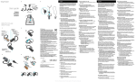
MOD-MP3-X and MOD-MP3-X-BAT
development boards
Users Manual
All boards produced by Olimex are ROHS compliant
Revision B, January 2011
Copyright(c) 2011, OLIMEX Ltd, All rights reserved
INTRODUCTION:
Page 1
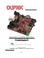
MOD-MP3-X is MP3 player module based on VS1053 Ogg
Vorbis/MP3/AAC/-WMA/MIDI audio decoder and an IMA ADPCM and userloadable Ogg Vorbis encoder; supports VBR (variable bit rate) for MP3; Supports
streaming. It also employs an on-board STM32F103RBT6 CORTEX-M3 microcontroller for smart control via UEXT.
MOD-MP3-X has three modes of operation:
- Standalone mode – compatible with the old revision MOD-MP3 player. In this
mode VS1053 controls the playback of files written on a micro SD card inserted in
the board. The user is provided with controls on volume, sound effects, starting,
stopping and sequencing of files to play.
- UEXT playback mode – in this mode the board can be connected as slave device to
host microcontroller which streams data to the codec via SPI.
- UEXT smart control mode – in this mode the on-board microcontroller manages
playback of files written to the micro SD card. The microcontroller acts as a slave
device and accepts user commands via UART. Commands include SD card directory listing, selecting of a file to play and playback and volume control.
MOD-MP3-X ships in two variants – with and without battery. The battery
variant employs a Li-ion 3.7 V, 1200 mAh rechargeable battery and an on-board battery charger.
BOARD FEATURES:
•
On-board STM32F103RBT6 ARM 32-bit Cortex™-M3 microcontroller
•
Based on VS1053 hardware decoder
•
3.7 V Li-ion battery and battery charger (for MOD-MP3-X-BAT)
•
UEXT to connect to host microcontroller (standard connector on our
ARM development boards)
•
Three modes of operation
•
EEPROM with firmware for standalone mode
•
micro SD card holder
•
USB
•
Stereo Audio microphone jack, Stereo Audio headphones jack
•
Can be used to record and playback
•
Triple action joystick: Forward, Reverse, Play/Pause action
•
Wake-up button
•
Two status leds
•
FR-4, 1.5 mm, soldermask, component print
•
Dimensions: 60 x 60 mm ( 2.36 x 2.36")
ELECTROSTATIC WARNING:
Page 2
The MOD-MP3-X board is shipped in protective anti-static packaging. The board
must not be subject to high electrostatic potentials. General practice for working
with static sensitive devices should be applied when working with this board.
BOARD USE REQUIREMENTS:
Cables: The cable you will need depends on the programmer/debugger you use. If
you use ARM-JTAG-EW, you will need USB A-B cable, for all types programmers
you will need ARM-JTAG-20to10 adapter.
Hardware: Programmer/Debugger ARM-JTAG-EW , ARM-USB-OCD, ARMUSB-TINY, ARM-USB-TINY-H , ARM-USB-OCD-H or other compatible
programming/debugging tool. For EEPROM programming you can use PICkit 2
development programmer/debugger from Microchip, because we don't offer a
suitable programmer, yet.
PROCESSOR FEATURES:
MOD-MP3-X board use STM32F103RBT6 microcontroller from
STMicroelectronics with these features:
−
−
−
−
Core: ARM 32-bit Cortex™-M3 CPU
−
72 MHz, 90 DMIPS with 1.25 DMIPS/MHz
−
Single-cycle multiplication and hardware division
−
Nested interrupt controller with 43 maskable interrupt channels
−
Interrupt processing (down to 6 CPU cycles) with tail chaining
Memories
−
128 Kbytes of Flash memory
−
20 Kbytes of SRAM
Clock, reset and supply management
−
2.0 to 3.6 V application supply and I/Os
−
POR, PDR, and programmable voltage detector (PVD)
−
4-to-16 MHz quartz oscillator
−
Internal 8 MHz factory-trimmed RC
−
Internal 32 kHz RC
−
PLL for CPU clock
−
Dedicated 32 kHz oscillator for RTC with calibration
Low power
−
Sleep, Stop and Standby modes
−
VBAT supply for RTC and backup registers
Page 3
−
−
−
2 x 12-bit, 1 μs A/D converters (16-channel)
−
Conversion range: 0 to 3.6 V
−
Dual-sample and hold capability
−
Synchronizable with advanced control timer
−
Temperature sensor
DMA
−
7-channel DMA controller
−
Peripherals supported: timers, ADC, SPIs, I2Cs and USARTs
Debug mode
−
−
−
−
Serial wire debug (SWD) & JTAG interfaces
49 fast I/O ports
−
49 5 V-tolerant I/Os
−
All mappable on 16 external interrupt vectors
−
Atomic read/modify/write operations
4 timers
−
3 general purpose timers
−
1 advanced control timer
Up to 9 communication interfaces
−
2 I2C interfaces (SMBus/PMBus)
−
3 USARTs (ISO 7816 interface, LIN, IrDA capability, modem control)
−
2 SPIs (18 Mbit/s)
−
CAN interface (2.0B Active)
−
USB 2.0 full speed interface
Page 4
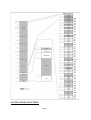
BLOCK DIAGRAM:
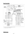
MEMORY MAP:
Page 5
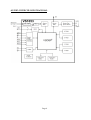
AUDIO CODEC FEATURES:
Page 6
−
Decodes Ogg Vorbis; MPEG 1 & 2 audio layer III (CBR +VBR +ABR); layers I &
II optional; MPEG4 / 2 AAC-LC(+PNS), HE-AAC v2 (Level 3) (SBR + PS);
WMA4.0/4.1/7/8/9 all profiles (5-384 kbps); WAV (PCM + IMA ADPCM);
General MIDI 1 / SP-MIDI format 0 files
−
Encodes Ogg Vorbis with software plugin
−
Encodes IMA ADPCM from mic/line (stereo)
−
Streaming support for MP3 and WAV
−
EarSpeaker Spatial Processing
−
Bass and treble controls
−
Operates with a single 12..13MHz clock
−
Can also be used with a 24..26MHz clock
−
Internal PLL clock multiplier
−
Low-power operation
−
High-quality on-chip stereo DAC with no phase error between channels
−
Zero-cross detection for smooth volume change
−
Stereo earphone driver capable of driving a 30-load
−
Quiet power-on and power-off
−
I2S interface for external DAC
−
Separate voltages for analog, digital, I/O
−
On-chip RAM for user code and data
−
Serial control and data interfaces
−
Can be used as a slave co-processor
−
SPI flash boot for special applications
−
UART for debugging purposes
Page 7
AUDIO CODEC BLOCK DIAGRAM:
Page 8
Page 9
S H IE LD
USB
USB_B
SWD
2
4
6
8
10
TMS/SWD
TCK/SWCLK
TDO
TDI
RST
GPH127SMT-02x05(PIN7-CUT)
1
3
5
7
9
R41
10K
1
R-T
2
R42
10K
TRST
TMS/SWD
TCK/SWCLK
TDO
TDI
RST
2
1
STM_RST
R48
560R
DREQ
MP3_RST
USBDM
USBDP
TMS/SWD
TCK/SWCLK
TDI
WAKE-UP
XCS
TXD
RXD
DCS
SPI1_SCK
SPI1_MISO
SPI1_MOSI
RST
C40
100nF
C38
C39
C37
100nF 100nF 100nF
TCK/SWCLK,TDI,TMS/SWD,TDO,RST,TRST
RST
R36
10K
100nF
C36
14
15
16
17
20
21
22
23
41
42
43
44
45
46
49
50
60
7
31
47
63
18
32
48
19
64
1
12
13
SPI2_MISO
SPI2_MOSI
STM32F103RBT6(LQFP64)
200R
SPI2_NSS
SPI2_SCK
SPI2_MISO
SPI2_MOSI
XCS
R34
TDO
TRST
DISC
5
6
54
8 BAT_SENSE
9 BAT_SENSE_E
10
11 +3.3V_UEXT
24 SPI1_MOSI
25 DCS
37
38
39
40
51 USB_DETECT
52
53 JACK_DETECT
2
STAT1
3
STAT2
4
26
27
28
55
56
57
58
59
61
62
29
30
33
34
35
36
R50
1M
SW-CS1
SPI2_NSS,SPI2_MOSI,SPI2_SCK,SPI2_MISO
C42 27pF
C43 27pF
Q2
8MHz
3.3V
SPI2_SCK
SPI2_MISO
SPI2_NSS
SPI2_MOSI
1uF
C25
22R
R9
10uF/10V
C27
10R
R8
R1
R2
R3
R-MAT1
1K
R4
C24 1uF
C20 1uF
22R
R6
100R
100K
100K
1N4148
D4
SW3
R38
R49
1M
47R
R28
100K
SW2
3.3V
SD/MMC
MICRO
CD/DAT3/CS
CMD/DI
VSS
VDD
CLK/SCLK
DAT0/DO
DAT1/RES
DAT2/RES
10K
1M
100pF
C21
http://www.olimex.com/dev
COPYRIGHT(C) 2011, OLIMEX Ltd.
Rev. B
R20
270k/1%
BAT_SENSE_E
R22
1M/1%
BAT_SENSE
R32
10K
STAT1
green
R43
470R
STAT1
STAT2
yellow
R44
470R
STAT_LEDS
WAKE-UP
3.3V
WAKE-UP
100nF
C32
VBAT
VOLTAGE
SCG325\3.5mm
MIC
3-R
2
1-L
MOD-MP3-X
C41
2
3
6
4
5
7
8
1
3.3V
R35
R37
200R
R33
SPI1_MOSI
R26
1K
SD/MMC
SW-CS1
SW1
DCS
3.3V
D3
R27
100K
1.8V
C13
10nF
C15
47nF
C16
10nF
USER INTERFACE
10uF/10V
C26
CL470nH/0805/0.47R
R45
R46
R47
L2
0R
R19
1
48
2
44
TX
RX
SCG325\3.5mm
HEADPHONES
3.3V
+
47uF/6.3V/TANT
PD0/OSC_IN
PD1/OSC_OUT
PD2/TIM3_ETR
PC0/ADC10
PC1/ADC11
PC2/ADC12
PC3/ADC13
PC4/ADC14
PC5/ADC15
PC6
PC7
PC8
PC9
PC10
PC11
PC12
PC13/ANTI_TAMP
PC14/OSC32_IN
PC15/OSC32_OUT
PB0/ADC8/TIM3_CH3
PB1/ADC9/TIM3_CH4
PB2/BOOT1
PB3/JTDO
PB4/JTRST
PB5/I2C1_SMBA
PB6/I2C1_SCL/TIM4_CH1
PB7/I2C1_SDA/TIM4_CH2
PB8/TIM4_CH3
PB9/TIM4_CH4
PB10/I2C2_SCL/USART3_TX
PB11/I2C2_SDA/USART3_RX
PB12/SPI2_NSS/I2C2_SMBAL/USART3_CK/TIM1_BKIN
PB13/SPI2_SCK/USART3_CTS/TIM1_CH1N
PB14/SPI2_MISO/USART3_RTS/TIM1_CH2N
PB15/SPI2_MOSI/TIM1_CH3N
PA0-WKUP/USART2_CTS/ADC0/TIM2_CH1_ETR
PA1/USART2_RTS/ADC1/TIM2_CH2
PA2/USART2_TX/ADC2/TIM2_CH3
PA3/USART2_RX/ADC3/TIM2_CH4
PA4/SPI1_NSS/USART2_CK/ADC4
PA5/SPI1_SCK/ADC5
PA6/SPI1_MISO/ADC6/TIM3_CH1
PA7/SPI1_MOSI/ADC7/TIM3_CH2
PA8/USART1_CK/TIM1_CH1/MCO
PA9/USART1_TX/TIM1_CH2
PA10/USART1_RX/TIM1_CH3
PA11/USART1_CTS/CANRX/USBDM/TIM1_CH4
PA12/USART1_RTS/CANTX/USBDP/TIM1_ETR
PA13/JTMS-SWDAT
PA14/JTCK-SWCLK
PA15/JTDI
BOOT0
NRST
VSS_1
VSS_2
VSS_3
VSS_4
VDD_1
VDD_2
VDD_4
VDD_3
VBAT
VSSA
VDDA
U5
1K
SPI2_MISO
VS1053
10uF/10V
C31
MICP/LINE1
LINE2
MICN
RCAP
35
3.3V
R40
10K
JTAG
3.3V
3.3V
R25
SPI2_NSS
SPI2_MOSI
GPIO0/SPIBOOT
GPIO1
GPIO2/DCLK
GPIO3/SDATA
GPIO4/I2S_LROUT
GPIO5/I2S_MCLK
GPIO6/I2S_SCLK
GPIO7/I2S_SDATA
42
39
46
15
TX
RX
1N4148
R39
10K
3.3V
TRST
TDO
LED
red
100nF
C30
33
34
9
10
36
25
11
12
GBUF
RIGHT
LEFT
VCO
27
26
L1
CL470nH/0805/0.47R
R3
100K
WAKE-UP
10nF
C35
USBDM
USBDP
SPI2_MOSI
25LC640
C33
SPI2_NSS
SPI2_MOSI
680K
22R
6
4
2
5
R1
22R
8
R2
R31
NA
U3
WP SCK
GND
SI
R3
5
4
5
3
1
CS
R4
2
3
R29
1.5k
SPI2_NSS
SPI2_MISO
3.3V
SPI2_MISO
EEPGM
4
C29
100nF
1
2
3
4
USB
47 k
10 k
3.3V
1
200R 2 SO VCC 7
HOLD 6
3
C28
3.3V
R-MAT2
100K
100nF
3.3V
U4
USBLC6-2P6(NA)
R30
1
6
DISC
3.3V
1
2
100nF
T1
DTA114YKA
R24
3.3V
HN1x2
SPI2_MOSI
R17
100R
100R
100R
45
43
38
R23
100K
EEPROM
47R
SPI1_SCK
SA_E
SW-CS1
SPI2_NSS R11
SPI2_MISO R12
SPI2_SCK R14
XTALI
XTALO
AVDD2
AVDD1
AVDD0
10K
R21
BOOT_E
HN1x3
SW-CS1
R18
HN1x3
DREQ_E
GND_
GND
12.288Mhz
18
17
DREQ
XDCS/BSYNC
XRESET
47
41
40
37
C34
3.3V
DREQ
SPI1_MISO,SPI 1_MOSI,SPI1_SCK,DCS,DREQ,RXD,TXD,XCS,MP3_RST
R10
1M
C23 33pF
Q1
8
13
GND
USB
GND
C19 33pF
DREQ
DCS
AGND3
AGND2
AGND1
AGND0
USB_DETECT
1uF
C18
1
2
1
2
D2
1N5819S
BATTERY-1
TB2/3.5mm
BATTERY-2
3
3.3V
TX
RX
C11
100nF
1N5819S
4.7K
5
GND
VOUT
3
2
1
R16
VSSPROG
1
3
1
MP3_RST
DREQ
DCS
XTEST
C10
C9
2
D1
R15
33k
2
BATT ERY CE
CHARGER
VDDVBAT
MCP73812T-420I/OT
1uF
C17
VIN
3
SPI1_MISO 30 SO
SPI1_MOSI 29
SI
SPI1_SCK 28 SCLK
23
XCS
XCS
32
U1
C7
1-L
YDJ-1134
5VDC
20k
4
+5V
2
100K
C6
3-R
PWR
C22
2
R7
C5
IOVDD2
IOVDD1
IOVDD0
R13 JACK_DETECT100n
BCD
1
SPI1_MISO
SPI1_MOSI
SPI1_SCK
XCS
100nF
2
1
C12
VLS_RST
10uF/10V
R5
100K
C4
100nF
+
R4
100K
3.3V
1.8V
100nF
CVDD3
CVDD2
CVDD1
CVDD0
C14
47uF/6.3V/TANT
MP3_RST
31
24
7
5
+3.3V_UEXT
MP3_RST/TXD
HN1x3
DCS
SPI1_MOSI
TXD
100nF
HN1x3
UEXT/BAT
UEXT
BH10S
3
2
1
100nF
3.3V
100K
10 DCS
8 SPI1_MOSI
R1
6
200R
SW-CS1
4
2
19
14
6
VR2(3.3V)
MCP1702T-3302E/MB
3
SPI1_SCK 9
SPI1_MISO 7
XCS 5
+3.3V_UEXT 1
DREQ/RXD
HN1x3
R2
3 RXD
2
1 DREQ
RXD
XCS
SPI1_MISO
SPI1_SCK
10uF/10V
DGND4
DGND3
DGND2
DGND1
DGND0
VBAT
1uF
C2
UEXT
C3
22
21
20
16
4
U2
3
1.8V
C8
+5V
GND
VOUT
VIN
MCP1700T-1802E/MB
1
2
VR1(1.8V)
VCORE
100nF
100nF
Battery Charger
1uF
C1
3V3
STAT2
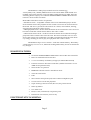
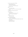
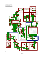
SCHEMATIC:
100nF
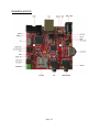
BOARD LAYOUT:
Page 10
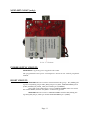
MOD-MP3-X-BAT (only):
POWER SUPPLY CIRCUIT:
MOD-MP3-X is typically power supplied with 5 VDC.
The programmed board power consumption is about 70 mA with all peripherals
enabled.
RESET CIRCUIT:
MOD-MP3-X reset circuit for VS1053 includes RC group - R7 (100kΩ) pullup and C12 (100nF), jumper MP3_RST, jumper VLS_RST, STM32F103RBT6 pin 43
(PA10/USART1_RX/TIM1_CH3) and VS1053 pin 3 (XRESET).
Note, that if VLS_RST jumper is closed, STM32F103RBT6 must not control
the VS1053 RESET, because VLS_RST is connected to ground.
MOD-MP3-X reset circuit for STM32F103RBT6 includes R36 (10kΩ) pullup, STM_RST jumper, SWD pin 10 and STM32F103RBT6 pin 7 (NRST).
Page 11
CLOCK CIRCUIT:
Quartz crystal Q1 (12.288 MHz) is connected to VS1053 pin 17 (XTALO)
and pin 18 (XTALI).
Quartz crystal Q2 (8 MHz) is connected to STM32F103RBT6 pin 5
(PD0/OSC_IN) and pin 6 (PD1/OSC_OUT).
JUMPER DESCRIPTION:
UEXT/BAT
When this jumper is shorted in position UEXT – the board is power suppied via
UEXT. When this jumper is shorted in position BAT – the board is power supplied via
BATTERY, USB or external power supply.
Default state is shorted in position BAT.
BOOT_E
SA_E
When this jumper is closed, codec is able to boot firmware from EEPROM. This is for
standalone mode.
Default state is closed.
This jumper connects SPI2_MOSI signal with SPI1_SCK signal.
Default state is closed.
DREQ_E
This jumper connects SPI1_SCK signal with DREQ signal.
Default state is closed.
MP3_RST/TXD and DREQ/RXD
When these jumpers are shorted in position MP3_RST and DREQ, the codec is
controlled direct via UEXT, without involving STM32F103RBT6. When these jumpers
are shorted in position TXD and RXD - via the UART interface of UEXT may be
submitted to STM32F103RBT6 commands to operate the codec.
Default states are shorted in positions MP3_RST and DREQ.
VLS_RST
STM_RST
When this jumper is closed, STM32F103RBT6 must not control the VS1053 RESET,
because VLS_RST jumper connects VS1053 pin 3 (XRESET) to ground
Default state is opened.
When this jumper is closed, STM32F103RBT6 is in reset.
Default state is closed.
R-T
This jumper connects RST signal with TRST signal.
Default state is opened.
BCD
This jumper connects the battery charger input and output. When is closed the battery
charger is disabled.
Default state is opened.
Page 12
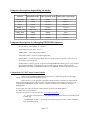
Jumpers description depending on mode:
Jumpers
Standalone mode
UEXT playback mode UEXT smart control mode
UEXT/BAT
BAT
UEXT
BAT
BOOT_E
closed
opened
opened
SA_E
closed
opened
opened
DREQ_E
closed
opened
opened
MP3_RST/TXD
MP3_RST
MP3_RST
TXD
DREQ/RXD
DREQ
DREQ
RXD
STM_RST
closed
closed
opened
VLS_RST
opened
opened
opened
Jumpers description for changing EEPROM firmware:
–SA_E, BOOT_E and DREQ_E – opened
–STM_RST and VLS_RST – closed
–DREQ/RXD – closed in position DREQ
–MP3_RST/TXD – closed in position MP3_RST
–UEXT/BAT – closed in position BAT (position of this jumper depends on the source of
power that you will choose)
In this jumper position you can program on board EEPROM with the proper programmer
(for example PICkit2). Note that you have to make custom adapter cable between
EEPROM programmer and EEPGM connector. See EEPGM connector description below.
Commands for UEXT smart control mode:
In this mode STM32F103RBT6 firmware has extra - Mass storage device, through
which you can save MP3 files to the SD card.
In this mode you can use RXD and TXD signals of UEXT connector to communicate
between MOD-MP3-X and your computer. For this purpose, for example, you can use our
module MOD-USB-RS232, which creates a virtual COM Port. The COM Port setting are
9600bps 8N1.
You can also use other our boards with UEXT to connect with MOD-MP3-X.
It is the list of used commands:
Note: For the latest version visit our site: www.olimex.com/dev
- "L" - lists the current directory and return its contents, directories are marked with
a <DIR> tag
- "CDIRNAME <name>" - switch the current directory to <name>, name should be
up to 8 characters long
Page 13
- "cnum <index>" - switch the current directory to the one with given <index>, as
displayed with the "L" command
- "." - returns to the parent directory, no higher than the root directory
- "PSONGNAME <name>" - plays file in the current directory by its <name>,
<name> should be in 8+3 format and the only extension supported is ".MP3"
- "pnum <num>" - plays file in the current directory by its <index>, starting from 0.
<index> may be calculated by the sequence number displayed with the "L"
command minus the number of directories in the current directory.
- "OFF" - turns the codec chip OFF, may be executed at any time
- "ON" - turns the codec chip ON, may be executed at any time
These commands have meaning only when playback is started:
- "C - stop playing current file, returns "Stopped."
- "+" - increase volume by 0.5dB step, 0 refers to max volume value, 254 is minimal
value.
- "-" - decrease volume by 0.5dB step, 0 refers to max volume value, 254 is minimal
value.
- "p" - play/pause toggle during playback, returns "Paused"/"Playing" respectively.
- "?" - display information on supported commands.
*Note: All of the commands should be followed by a newline character ('\n' or
"\r\n")!
INPUT/OUTPUT:
Status Led (green) with name STAT1, connected to STM32F103RBT6 pin 2
(PC13/ANTI_TAMP).
Meaning of the status LED (STAT1) activity:
- When in mass storage mode the LED indicates SD card read/write activity.
- When playing a file in MP3 player mode LED is constantly ON.
- When playback is paused in MP3 player mode LED is blinking with 0.5Hz period.
Battery level status Led (yellow) with name STAT2, connected to STM32F103RBT6
pin 3 (PC14/OSC32_IN).
Battery level status LED (STAT2) activity:
- When powered by the battery the MOD-MP3-X indicated low battery level. If
voltage of the battery falls below 3.3V then the STAT2 LED starts to blink.
- If an external power source is connected, then battery starts charging. In this case
STAT2 LED is constantly lit while battery is charging and turns off when battery is
fully charged.
Power-on led (red) with name LED is used by VS1053 firmware and is connected to
STM32F103RBT6 pin 36 (SPI2_MOSI).
Wake-up button, connected to STM32F103RBT6 pin 14 (PA0-WKUP).
Switch with name Joystick with three positions: SW1, SW2 and SW3.
Page 14
Position
Short Keypress
Long Keypress
SW1 (to power jack)
Next Song
Volume up
SW2 (to headphones)
Previous Song
Volume down
SW3 (pressed)
Pause/Play
-
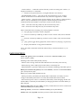
EXTERNAL CONNECTORS DESCRIPTION:
PWR_JACK:
Pin #
Signal Name
1
Power Input
2
GND
UEXT:
Pin #
Signal Name
1
+3.3V_UEXT
2
GND
3
DREQ/RXD
4
MP3_RST/TXD
5
XCS
6
SW-CS1
7
SPI1_MISO
8
SPI1_MOSI
9
SPI1_SCK
10
DCS
Page 15
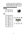
SWD:
Pin #
Signal Name
1
VCC (3.3V)
2
TMS/SWD
3
GND
4
TCK/SWCLK
5
GND
6
TDO
7
CUT (NC)
8
TDI
9
GND
10
RST
USB:
Pin #
Signal Name
1
USB_DETECT
2
USBDM
3
USBDP
4
GND
Page 16
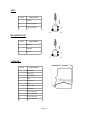
MIC:
Pin #
Signal Name
1
MICN
2
MICP/LINE1
3
MICP/LINE1
HEADPHONE:
Pin #
Signal Name
1
GBUF
2
RIGHT
3
LEFT
SD/MMC:
Pin #
Signal Name
1
MCIDAT2
2
SPI2_NSS
3
SPI2_MOSI
4
VCC
5
SPI2_SCK
6
GND
7
SPI2_MISO
8
MCIDAT1
9
Not Connected
10
Not Connected
11
Not Connected
12
Not Connected
Page 17
EEPGM:
Pin #
Signal Name
1
VCC
2
GND
3
SPI2_MISO
4
SPI2_MOSI
5
SPI2_NSS
6
Via BOOT_E to SW-CS1
Page 18
MECHANICAL DIMENSIONS:
Page 19
AVAILABLE DEMO SOFTWARE:
MOD-MP3-X-Demo
Page 20
ORDER CODE:
MOD-MP3-X - assembled and tested board
How to order?
You can order to us directly or by any of our distributors.
Check our web www.olimex.com/dev for more info.
Revision history:
Revision B, January 2011
Page 21
Disclaimer:
© 2011 Olimex Ltd. All rights reserved. Olimex®, logo and combinations thereof, are registered
trademarks of Olimex Ltd. Other terms and product names may be trademarks of others.
The information in this document is provided in connection with Olimex products. No license, express
or implied or otherwise, to any intellectual property right is granted by this document or in
connection with the sale of Olimex products.
Neither the whole nor any part of the information contained in or the product described in this
document may be adapted or reproduced in any material from except with the prior written
permission of the copyright holder.
The product described in this document is subject to continuous development and improvements. All
particulars of the product and its use contained in this document are given by OLIMEX in good faith.
However all warranties implied or expressed including but not limited to implied warranties of
merchantability or fitness for purpose are excluded.
This document is intended only to assist the reader in the use of the product. OLIMEX Ltd. shall not
be liable for any loss or damage arising from the use of any information in this document or any error
or omission in such information or any incorrect use of the product.
Page 22


![[DRAFT] DEMO908JL16 User`s Manual](http://vs1.manualzilla.com/store/data/005639706_1-2a84cd2ce2f0b318fdb7aae7896f2a79-150x150.png)