1
Titanium CLI
Reference Guide
© GlobespanVirata 1999-2003
-3-
Table of Contents
1
Introduction..........................................................9
2
Quick Start.........................................................11
3
CLI Introduction.................................................12
4
Unit Configuration..............................................13
4.1
Default Configuration................................................13
4.1.1
System Sizing Parameters ........................17
4.2 Modifying the Unit’s MAC Address and
Serial Number..................................................................19
4.3 Modifying the Unit Configuration via Script
Files..................................................................................19
4.3.1 Notes on Using Script File
Configuration ..........................................................20
4.4
Managing Configuration Changes...........................20
4.5 Using FTP/TFTP to Upgrade and Retrieve
the Flash Image...............................................................21
5
4.5.1
Data configuration Upgrade ......................22
4.5.2
Recovering from a Failed Upgrade ................22
Interfaces and Operating Mode ........................24
5.1
Interfaces – Overview...............................................24
5.2
Configuring the Ethernet Port ..................................24
5.3
Configuring Virtual Ethernet Interfaces....................27
5.4
Configuring the WAN ATM Port...............................27
5.5
Configuring Permanent Virtual Circuits ...................28
5.5.1
AAL5 Data Encapsulation Method .................29
5.5.2 ATM Service Categories: UBR,
CBR, GFR, NRTVBR and RTVBR ....................30
5.6
Configuring Switched Virtual Circuits (SVCs)..........33
5.7
Configuring PPP Interfaces......................................36
5.7.1 Creating a Login Name and
Password for a PPP Interface.............................37
5.7.2
PPPoE Interfaces ........................................38
5.7.3
PPPoA Interfaces ........................................39
5.7.4 Checking the IP Address of a PPP
Interface...................................................................40
-4-
5.7.5 Configuring the PPP Auto
start/stop Feature ..................................................40
5.7.6
5.8
IP Unnumbered PPP Interfaces ...............40
Configuring the Operating Mode..............................43
5.8.1
Bridge Mode .................................................43
5.8.2
WAN to WAN bridging ...............................46
5.8.3
Router Mode ...................................................46
5.8.4
Bridge Router Autosense (BRAS) ...........49
5.8.5 Zero Installation PPPoE Bridge
(ZIPB) Mode ...........................................................50
6
7
Viewing and Modifying DSL Information...........54
6.1
Modifying the DSL Configuration .............................54
6.2
Viewing DSL Parameters and Statistics..................55
Configuring IP and Routing Management.........57
7.1
Configuring Routing on LAN Hosts..........................57
7.2
Configuring Routes...................................................57
7.3
Routing Mode ...........................................................58
7.4
RIP ............................................................................59
7.4.1
RIP Global Configuration ...........................59
7.4.2
RIP Interface Configuration .......................59
7.5
8
9
10
IGMP.........................................................................60
Virtual Private Network......................................64
8.1
Overview...................................................................64
8.2
L2TP .........................................................................65
8.3
Configuration details.................................................67
8.4
L2TP Traps...............................................................72
Configuring DNS Relay.....................................73
9.1
Overview of DNS Relay ...........................................73
9.2
Configuration Details ................................................73
Configuring DHCP Server and DHCP
Relay ..............................................................74
10.1 Default DHCP Configuration on the
Titanium Reference Unit.................................................74
10.2
Configuring Unit as DHCP Server..........................74
10.2.1
Creating DHCP Pools ..............................75
10.2.2
Excluding Addresses from a Pool .........77
10.2.3
Modifying and Deleting Pools .................78
-5-
10.2.4
Creating Static DHCP Assignments.............78
10.2.5
Enabling the DHCP Server...........................79
10.2.6
DHCP- DNS Relay Interaction ...............80
10.2.7 Viewing DHCP Server Address
Assignments ...........................................................80
10.3
Configuring DHCP Relay........................................80
10.3.1 Configuring the DHCP Relay
Interfaces ................................................................80
10.3.2 Specifying the DHCP Server IP
Address ...................................................................81
10.3.3
10.4
Using a DHCP Server on the LAN .........................82
10.5
DHCP Traps............................................................82
10.5.1
Duplicate IP Address Trap ......................82
10.5.2
Low Threshold Hit Trap ...........................82
10.6
11
12
Enabling DHCP Relay Mode........................81
ForceRenew............................................................83
Simple Network Time Protocol..........................84
11.1
Overview .................................................................84
11.2
SNTP implementation details .................................84
11.3
Configuration details ...............................................86
Layer 2 Security ................................................88
12.1
Raw Filtering – Overview........................................88
12.1.1 Using Raw Filtering Rules and
Subrules ..................................................................89
12.1.2
13
Raw Filtering Global Configuration...............91
12.2
Protocol Blocking ....................................................91
12.3
L2 Wall.....................................................................92
12.3.1
Overview.....................................................92
12.3.2
Configuration Files ....................................93
12.3.3
AutoDetect Algorithm ...............................93
12.3.4
Assumptions ..............................................94
12.3.5
Sample Configuration Files ..........................94
Layer 3 Security ................................................96
13.1
NAT .........................................................................96
13.1.1 Default NAT Configuration on the
Titanium Unit............................................................97
13.1.2
Configuring NAT Direction ......................98
-6-
13.1.3
The napt rule .................................................98
13.1.4
The rdr Rule .............................................100
13.1.5
The basic and filter Rules ......................102
13.1.6
The bimap Rule .......................................103
13.1.7
The pass Rule .........................................103
13.1.8
Configuring ALGs........................................103
13.1.9
Enabling NAT ..........................................106
13.2
Firewall ..................................................................106
13.2.1
Attack protection .....................................106
13.2.2
Firewall features ......................................110
13.2.3
Configuration details...............................111
13.3
IP Filtering and IP Sessions..................................113
13.3.1
Using IP Filtering Rules .........................115
13.3.2 Configuring Time-of- day based
rules 117
13.3.3 IP Sessions – Advanced
Configuration Issues ...........................................120
13.3.4
14
15
IP Filtering Global Configuration ..........122
Usage Control .................................................124
14.1
Overview ...............................................................124
14.2
User Authentication process.................................125
14.3
Configuration using CLI ........................................130
Application Security – Surfing Profile ..............132
15.1
Surfing Profile........................................................132
15.2
Invoking the Surfing Profile Feature .....................132
15.3
Types of files .........................................................132
15.3.1 Surfing profile - modes of
operation ...............................................................133
15.4
16
Surfing profile – feature details.............................135
Auto-configuration ...........................................136
16.1
AutoDetect.............................................................136
16.1.1
Overview...................................................136
16.1.2 Configuring the Modem to Work with
AutoDetect..............................................................137
16.1.3
AutoDetect Configuration Options..............138
16.1.4
Considerations ............................................140
16.2
Auto-configuration Using ILMI (TR-037) ..............141
-7-
16.2.1 Starting Auto- configuration
through Default ....................................................142
16.2.2
time
Starting auto- configuration at run
16.2.3
Viewing auto- configured VCs ..............144
16.2.4
Best effort configuration .........................145
16.2.5
VCC change and Cold Start Trap........146
16.2.6
Configuration Conflicts...........................146
16.2.7
Configuration mismatch Traps .............146
16.2.8
Constraints ...............................................146
144
16.2.9 Recommended parameters
required from network.........................................147
17
Other Device Access Mechanisms .................148
17.1 Simple Network Management Protocol
(SNMP) ..........................................................................148
17.1.1
SNMP Communities...............................148
17.1.2
SNMP Hosts ............................................148
17.1.3
SNMP Traps ............................................149
17.1.4 Providing SNMP Access Across
the Modem ............................................................149
17.2
Web-based Interface ............................................150
17.2.1 Accessing the Web- based
Interface.................................................................150
17.2.2 Accessing the Quick
Configuration Page .............................................151
17.2.3
User Instructions .........................................152
17.2.4
Web-based Diagnostics ........................152
17.3
18
L2 Agent Module...................................................153
System Maintenance.......................................155
18.1
Diagnostics............................................................155
18.1.1
18.2
Diagnostics page of the HTTP Agent...................155
18.2.1
18.3
Checking IP Connectivity ......................155
Diagnostics - categories ........................155
ATM Traffic Diagnostics........................................156
18.3.1
OAM F5 CC .............................................157
18.3.2
OAM Loopback ...........................................159
18.4
Traps .....................................................................160
-8-
18.5 Requesting Status and Statistical
Information.....................................................................161
18.6
Viewing complete system configuration...............163
18.7
Managing User Accounts .....................................164
18.7.1
Creating User Accounts.........................164
18.7.2
Deleting User Accounts ..............................165
18.8
Changing the Login Password .............................165
18.9
Modifying System Parameters .............................166
18.10 Configuring Host Name and Domain
Name on the Modem ....................................................166
18.11
Debugging using Memory Location ...................169
18.12
Serial Port Authentication ...................................169
18.12.1
19
20
Using CLI Commands .........................169
Shell Tutorial ...................................................171
19.1
Shell Tutorial - Overview.......................................171
19.2
Shell Programming Tutorial ..................................172
19.2.1
A First Script.............................................173
19.2.2
Variables ...................................................174
19.2.3
IF-ELSE Construct..................................175
19.2.4
Goto ...........................................................177
19.2.5
Readout and Search ..............................179
19.2.6
Return........................................................182
19.2.7
Keywords ..................................................185
19.2.8
Symbols ....................................................185
Glossary ..........................................................186
-9-
1 Introduction
This document contains the following chapters:
Introduction, provides basic information on this
document.
Chapter 2 shows how to set up, configure, and operate
the Titanium.
Chapter 3 gives a brief overview of the main features of
the Command Line Interface (CLI).
Chapter 4 defines and describes the reference unit’s
default configuration, and explains how you can alter the
current configuration using flat files.
Chapter 5 shows how to configure the unit’s interfaces,
and how to change its operating mode.
Chapter 6 explains the CLI commands that can be used
to modify and display DSL-related parameters and statistics.
Chapter 7 shows how to use CLI to configure IP routes.
Chapter 8 shows how to use the Layer 2 Tunneling
protocol (L2TP) to enable the unit to provide VPN services.
Chapter 9 shows how to configure the modem as a DNS
relay server.
Chapter 10 shows how to use CLI to configure the
Dynamic Host Configuration Protocol (DHCP) server and or
client functions.
Chapter 11 describes the configuration options of the
Simple Network Transfer Protocol.
Chapter 12 describes raw filtering, protocol blocking and
the L2 Wall feature.
Chapter 13 details information on configuring NAT,
Firewall and IP Filtering.
Chapter 14 discusses the new Usage Control feature of
the unit.
Chapter 15 discusses the surfing profile feature that
provides application security.
Chapter 16 discussing how auto configuration is possible
with auto detect and TR-37 support.
Chapter 17 discusses mechanisms for management
access to the modem, using SNMP, Web-based interface,
and L2 Agent.
Chapter 18 shows how to perform basic maintenance
functions using CLI.
Chapter 19 helps you understand how to use shell scrips
- 10 -
to your advantage, and provides a tutorial on shell
programming.
A glossary of terms used in this document is also provided.
- 11 -
2 Quick Start
See Setup documention supplied with your router
- 12 -
3 CLI Introduction
See full Titanium CLI manual.
- 13 -
4 Unit Configuration
This chapter describes the default configuration programmed into
the flash memory, as well as how to modify the configuration after
boot-up.
4.1
Default Configuration
The unit’s default configuration is established by the factory defaults
file named TEFacs.txt. You customize the default configuration by
modifying this file, then creating and loading a new flash image (a
description of this process and sample factory defaults files are
provided in the Image Handling User Manual). At boot-up, the CLI
commands in this file are automatically executed. Once the unit is
operational, its configuration can be changed interactively using CLI,
or in batch mode by script file upload (described in section ).
The following list describes example settings that may appear in the
default TEFacs.txt:
CLI user accounts
One superuser account: name = ‘DSL’, password = ‘DSL’
Maximum number of VCs: 8
Maximum number of IP sessions: 192
LAN interfaces
Ethernet port: eth-0, IP address 192.168.7.1, subnet mask 255.255.255.0
DSL — configured for multimode coding standard
WAN interfaces
ATM port: atm-0; maximum VCs allowed = 8
ATM VC: aal5-0, lower interface atm-0, VPI = 0, VCI = 38
PPPoE interface: ppp-0, lower interface aal5-0, default route
PPP user name ‘guest’, password ‘guest’, PAP authentication
RIP — Enabled on PPP interface
DHCP — enabled with one pool for LAN computers:
Pool ID = 1, address range = 192.168.7.3 to 192.168.7.34,
mask 255.255.255.0
NAT — enabled with an NAPT rule for translating
local private addresses to the public address assigned to
ppp-0
Bridging — enabled with ethernet interface defined
as bridgeable
- 14 -
IP Filter — enabled, with various rules configured for
high, medium, and low security.
Below lists the CLI commands in the factory defaults file that
configures the unit as a router.
create user name DSL passwd DSL root
modify system logthresh 1
size maxvc 8 max1483vc 8 maxppe 8
modify nbsize maxipsess 192
create ethernet intf ifname eth-0 ip 192.168.7.1
mask 255.255.255.0 inside
modify dsl config gdmt
create atm port ifname atm-0 maxvc 8
create atm trfdesc trfindex 0 NOCLP_NOSCR
create atm vc intf ifname aal5-0 lowif atm-0 vpi
0 vci 38 vcmux
create ppp security ifname ppp-0 CHAP login guest
passwd guest
create ppp intf ifname ppp-0 start lowif aal5-0
droute true PPOA usedhcp false outside usedns
true
create rip intf ifname ppp-0
create dhcp relay intf ifname ppp-0
create nat rule entry ruleid 1 napt
modify nat global enable
modify ipf global pubdefact accept
modify ipf global pvtdefact deny
modify ipf global dmzdefact accept
create ipf rule entry ruleid 10 dir in act deny
destaddr bcast seclevel high
create ipf rule entry ruleid 20 dir in act deny
destaddr eq 255.255.255.255 seclevel high
create ipf rule entry ruleid 30 ifname private
dir in act accept storestate enable seclevel high
medium low
- 15 -
create ipf rule entry ruleid 40 ifname private
dir out srcaddr self act accept storestate enable
seclevel high medium low
create ipf rule entry ruleid 50 ifname private
dir out inifname dmz transprot eq udp destport eq
num 53 act accept storestate enable seclevel high
medium low
create ipf rule entry ruleid 60 ifname private
dir out inifname dmz transprot eq tcp destport eq
num 53 act accept storestate enable seclevel high
medium low
create ipf rule entry ruleid 70 ifname private
dir out inifname dmz transprot eq tcp destport eq
num 25 act accept storestate enable seclevel high
medium low
create ipf rule entry ruleid 80 ifname private
dir out inifname dmz transprot eq tcp destport eq
num 110 act accept storestate enable seclevel
high medium low
create ipf rule entry ruleid 90 ifname private
dir out inifname dmz transprot eq tcp destport eq
num 21 act accept storestate enable seclevel
medium low
create ipf rule entry ruleid 100 ifname private
dir out inifname dmz transprot eq tcp destport eq
num 80 act accept storestate enable seclevel
medium low
create ipf rule entry ruleid 110 ifname private
dir out inifname dmz transprot eq tcp destport eq
num 23 act accept storestate enable seclevel low
create ipf rule entry ruleid 120 ifname private
dir out inifname dmz transprot eq icmp act accept
storestate enable seclevel low
create ipf rule entry ruleid 130 ifname dmz dir
out inifname private transprot eq tcp destport eq
num 23 act deny seclevel high
create ipf rule entry ruleid 140 ifname dmz dir
out inifname public transprot eq udp destport eq
num 53 act deny seclevel high
create ipf rule entry ruleid 150 ifname dmz dir
out inifname public transprot eq tcp destport eq
num 53 act deny seclevel high
create ipf rule entry ruleid 160 ifname dmz dir
out inifname public transprot eq tcp destport eq
num 21 act deny seclevel high
- 16 -
create ipf rule entry ruleid 170 ifname dmz dir
out inifname public transprot eq tcp destport eq
num 23 act deny seclevel high medium low
create ipf rule entry ruleid 180 ifname dmz dir
out inifname public transprot eq icmp act deny
seclevel high medium
create ipf rule entry ruleid 190 ifname public
dir out transprot eq tcp destport eq num 23 act
deny seclevel high
create ipf rule entry ruleid 200 ifname public
dir out srcaddr self act accept storestate enable
seclevel high medium low
create ipf rule entry ruleid 210 ifname public
dir in act deny destaddr bcast seclevel medium
create ipf rule entry ruleid 220 ifname public
dir in act deny destaddr eq 255.255.255.255
seclevel medium
create ipf rule entry ruleid 230 ifname public
dir in act deny transprot eq udp destport eq num
7 seclevel high medium
create ipf rule entry ruleid 240 ifname public
dir in act deny transprot eq udp destport eq num
9 seclevel high medium
create ipf rule entry ruleid 250 ifname public
dir in act deny transprot eq udp destport eq num
19 seclevel high medium
create ipf rule entry ruleid 260 ifname public
dir in destaddr self transprot eq tcp destport eq
num 80 act deny seclevel high medium low
create ipf rule entry ruleid 270 ifname public
dir in destaddr self transprot eq udp destport eq
num 53 act deny seclevel high
create ipf rule entry ruleid 280 ifname public
dir in destaddr self transprot eq tcp destport eq
num 53 act deny seclevel high
create ipf rule entry ruleid 290 ifname public
dir in destaddr self transprot eq tcp destport eq
num 21 act deny seclevel high medium low
create ipf rule entry ruleid 300 ifname public
dir in destaddr self transprot eq tcp destport eq
num 23 act deny seclevel high medium low
create ipf rule entry ruleid 310 ifname public
dir in destaddr self transprot eq icmp act deny
seclevel high medium
create ipf rule entry ruleid 320 ifname public
dir in destaddr self transprot eq udp destport eq
- 17 -
num 53 act accept storestate enable seclevel
medium low
create
dir in
num 53
medium
ipf rule entry ruleid 330 ifname public
destaddr self transprot eq tcp destport eq
act accept storestate enable seclevel
low
create ipf rule entry ruleid 340 ifname public
dir in act deny isipopt yes seclevel high
create ipf rule entry ruleid 350 ifname public
dir in act deny isfrag yes seclevel high
create ipf rule entry ruleid 360 ifname dmz dir
in destaddr self transprot eq tcp destport eq num
80 act deny seclevel high medium
create ipf rule entry ruleid 370 ifname dmz dir
in destaddr self transprot eq tcp destport eq num
21 act deny seclevel high medium
create ipf rule entry ruleid 380 ifname dmz dir
in destaddr self transprot eq tcp destport eq num
23 act deny seclevel high medium
create ipf rule entry ruleid 390 ifname dmz dir
in act accept storestate enable seclevel high
medium low
end
For detailed information on all CLI commands (except modify
nbsize and size, which are described in section ), see the
Virata CLI Manual.
4.1.1
System Sizing Parameters
The first two lines of the factory defaults file specify “sizing”
parameters. These parameters set upper limits on some of the basic
elements of the system, e.g., the number of VCs or IP sessions.
The sizing parameters are specified using the size and modify
nbsize commands. While these commands are available in CLI,
they are “hidden” from the user; they do not appear in the output of
the help command and are otherwise undocumented. This is
because these commands are only for OEM use; end users should
have no knowledge of these commands.
Because parts of the system, the size and modify nbsize commands must come at the beginning of the
factory defaults file.
- 18 -
The size command
This command sets upper limits on certain system properties. Its
parameters are:
maxvc and max1483vc – Maximum number of VCs
(both: default 2)
1)
maxppe – Maximum number of PPPoE sessions (default
maxmac – Maximum number of MAC addresses that are
learned by the bridge forwarding table (default 256)
maxpfrawrule – Maximum number of raw filter rules
(default 8)
maxpfrawsubrule – Maximum number of raw filter
subrules (default 8)
maxipfrule - Maximum number of IP filter rules
(default 8)
You should set these parameters in accordance with the anticipated
needs of a typical end user of your product.
The modify nbsize command
This command is used to modify
the maximum number of IP sessions that can be
active at any given time the TELNET server port
the FTP server port
the HTTP server port.
An IP session is a connection between two applications, one running on one of your LAN’s hosts
and the other running on a host on the WAN, e.g., a connection between a host on your LAN
and an Internet web site.
To see the maximum number of IP sessions currently configured or port on which
TELNET, HTTP, FTP servers are running, enter:
$ get nbsize
To limit the maximum number of active IP sessions to 256, enter:
$ modify nbsize maxipsess 256
To modify the TELNET server port to 9000, enter:
$ modify nbsize telnetport 8000
To modify the FTP server port to 1000, enter:
$ modify nbsize ftpport 9000
- 19 -
To modify the HTTP server port to 8000, enter:
$ modify nbsize httpport 10000
The modify nbsize command does not take effect until the next
system reboot occurs. To initiate a system reboot, enter the
following pair of commands:
$ commit
$ reboot last
4.2
Modifying the Unit’s MAC Address and Serial Number
When you build a software image, it is coded with a default MAC
address and serial number. You can change this data on a particular
unit using the CLI.
Serializing an image
To change the MAC address and serial number on a board, enter:
do serialize AA-BB-CC-DD-FF-12 111122233334444
The MAC address is a 12-digit hexadecimal number, which can be entered with dashes, as
shown, or as a single string. The same MAC address applies to all the unit’s LAN-side
interfaces (e.g., eth-0 and usb-0).
The serial number can contain up to 24 alphanumeric characters.
4.3
Modifying the Unit Configuration via Script Files
Besides CLI, another way of modifying the unit’s current
configuration is to use the script file upload method. Unlike CLI, this
method does not require a serial port. This method is meant to be
used primarily by ISPs, as a quick and easy way to update the
configuration of their customers’ boxes.
The script file is uploaded to the unit’s IP address via ftp or tftp.
Once the script file has been uploaded to the unit, the file may be
executed immediately or at a later time, depending on the
autoupdate flag (see note below). If the autoupdate flag is set to
true, the CLI commands in the configuration file are executed
immediately. If however, the autoupdate flag is set to false, then the
CLI commands are held in RAM and are not executed until the
apply command is issued via CLI.
- 20 -
Please refer to section in this document for details on CLI Scripting and Script Programming.
The autoupdate flag indicates whether configuration files will be executed immediately or only upon
issue of an apply command. For more details on the autoupdate flag and the commands related to its use, see
the CLI Reference Manual.
4.3.1
Notes on Using Script File Configuration
Important points concerning script file configuration include:
The script file can only be used to change the
current configuration. It cannot be used to update or
replace the factory defaults file (default configuration
file) in the flash image.
In order to modify an existing interface, it may be
necessary for the script file to delete the interface first,
and then recreate it.
In order for the new configuration to be saved to
flash memory, the script file must contain the commands
commit and reboot.
4.4
Managing Configuration Changes
Whenever you change the unit's configuration and do a commit, the
changes are saved into the flash. Doing a reboot after a commit
reboots the unit with the latest changes. The reboot command
supports the following options.
last: to reboot the unit using the latest saved
configuration use the reboot last command.
backup: to reboot the unit using the configuration of the
operation that was committed before the last commit
operation, use the reboot backup command.
Default: to reboot the unit using the default
configuration, use the reboot default command.
Clean: to reboot the unit with zero configuration, use the
reboot clean command. This assumes that the user has a
serial port connected to the unit. This is so, because in a
clean configuration even Ethernet is not configured.
Minimum - to reboot the unit with only the size (with all
default parameters), create ethernet intf and create
user commands executed, use the reboot minimum
command.
The Ethernet interface and the user are created with the parameters used in the default configuration. The
minimum configuration aims to configure the unit so as to allow a telnet to it from the LAN.
Note that when you reboot with a given configuration, say reboot clean, the other configurations are not
lost. To go back to the last saved configuration after you have done a reboot clean, just do a reboot last.
- 21 -
4.5
Using FTP/TFTP to Upgrade and Retrieve the Flash Image
You can use FTP/TFTP to upload/download code to/from a unit’s
flash memory, assuming that a functioning image is already loaded
on the unit. Uploads and downloads can be performed from a
computer connected to the device through an IP-enabled interface,
such as its LAN interface.
Uploading to the unit enables you to upgrade the image as you
obtain new software releases from your router supplier.
Downloading from the unit to your PC enables you to store code and
configuration files before overwriting them with new code.
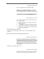
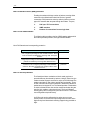
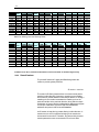
You can transfer an entire or a partial flash image. The filename
must be one of those described in Table below.
Files Used with TFTP Upload/Download
Filename
TEImage.bin
TEPatch.bin
Description
Entire binary image.
Compressed file containing patch code representing
one or more of the code blocks (for example, the DSL
firmware and application code blocks). You can use
TEPatch.bin to upgrade several blocks at a time,
without overwriting all blocks. See the Image Handling
User’s Manual for more information about the content
of TEPatch.bin and how to modify it to create the
desired patch file.
Uploading Example
To upload a file to the unit, you can type a command such as the
following at a DOS prompt on your PC (replace the IP address
shown with the LAN port port IP address on the unit):
TFTP -i 192.168.1.1 put TEImage.bin
Reboot the unit when the upload is complete. See the section
Recovering from a Failed Upgrade if the upload is not
successful.
Downloading Example
To download a file, such as the configuration file, use a command
such as the following:
- 22 -
TFTP -i 192.168.1.1 get TECfg.bin
If you later change the unit’s configuration and find that it the device
is not working properly, you can upload this file to restore a knowngood configuration.
4.5.1
Data configuration Upgrade
Data configuration upgrade using TEpatch.bin will be required if you
have committed certain CLI commands in a previous release, and
want the same commands to work in an upgraded release.
For a list of supported releases, please refer to the relevant release notes. Normally, if the board fails to
come up with the committed configuration, it reboots and tries to come up with the default configuration.
But, while upgrading only a best effort attempt is made to recreate the older configuration. That is, errors
are ignored. Hence, always check, after an upgrade, whether the new configuration appears as desired.
4.5.2
Recovering from a Failed Upgrade
If the upgrade process fails while uploading the application code file,
(for example, your FTP/TFTP connection is lost during the process),
or if for any reason the new application code fails to boot after
loading, the device may boot to a special TFTP mode that enables
you to continue the upgrade. This procedure enables you avoid
having to re-flash the device with an entire image using a serial
connection to the flash header.
This TFTP server mode is invoked automatically when the
application checksum test fails during boot-up. If you have a serial
connection to the board, the following message will display on the
terminal:
Testing Application Checksum ... Failed
TFTP Server Started ...
Please upload flash image to 192.168.1.1
In addition, all the software controlled test LEDs will blink at about
twice per second. This indicates that the application code has not
been loaded and all subsequent routine boot processes were
aborted. The unit’s built-in TFTP server is invoked and an IPenabled Ethernet interface is set up with the following properties:
IP Address: 192.168.1.1
Mask: 255.255.255.0
To continue the image upgrade via TFTP, verify that the IP
properties on the PC assign it to the same subnet as this Ethernet
interface. Then, upload the new application code file via TFTP (FTP
is not supported in this mode). The LEDs will blink rapidly as the
image is uploaded.
- 23 -
You can also access this mode as a shortcut if you want to boot a
board solely to perform an image upgrade via TFTP. To force a unit
into this mode, begin booting the board and monitor the boot
messages on your PC. Before “Testing Application Checksum.....”
displays (or during), type “tao” and press <Backspace>. The
ordinary boot process will be aborted and the board will boot in the
TFTP mode as described above.
- 24 -
5 Interfaces and Operating Mode
This chapter briefly discusses the unit’s interfaces, and explains how
to create and configure the interfaces needed for the bridge and
router operating modes, as well as how to select each mode.
5.1
Interfaces – Overview
At the physical level, the unit provides WAN-LAN connectivity
through its physical WAN, and LAN ports. At the logical level, the
connection can be made in a number of ways, depending on the
virtual interfaces configured on top of the physical ports and how
these interfaces are connected.
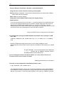
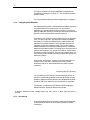
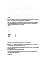
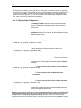
Figure below shows the virtual interfaces you can define on each
physical port
router
PPP*
interfaces
Virtual Ethernet
interfaces
USB
interface
usb-0
USB Port
Ethernet
interface
bridge or router
ppp-0
eoa-0
EoA
interfaces
veth-0
eth-0
LAN Port
VCs
aal5-0
ATM
interface
atm-0
WAN/DSL Port
Virtual
Interfaces
Physical
Interfaces
* Per VC: 1 PPPoA, or 1 or more PPPoE
In order to create an interface, you first create all the interfaces
below it, starting at the lowest interface. For instance, to create a
PPP interface, you first create the ATM port, then a VC.
5.2
Configuring the Ethernet Port
The Ethernet port is a physical port on that enables you to connect
the unit to a computer or Ethernet network. You can configure only
one physical Ethernet port, eth-0; however, you can define multiple
virtual ethernet interfaces over this port, as described in section on
page -27. This port can be created with or without an IP address (no
IP address is required if it is a bridge port).
- 25 -
When creating the Ethernet port, you may need to consider the
following:
IP address and subnet – To connect the unit to an
existing LAN whose subnet differs from the Ethernet
port’s default subnet (192.168.1.1, mask 255.255.255.0),
assign the Ethernet port an IP address in the same
subnet as your LAN. (Alternatively, you would have to
assign to each LAN computer a new IP address and
mask that places it in the same subnet as the Ethernet
port.)
Commands related to the Ethernet port are briefly described below.
For a complete listing of these commands, including parameters and default values, refer to the
SAR110CLI Manual
Creating the Ethernet port
To create the Ethernet port eth-0, enter:
$ create ethernet intf ifname eth-0 ip 192.168.1.1 mask 255.255.255.0
To display information on the Ethernet port, enter:
$ get ethernet intf
Setting Interface security type
You can set the interface security type to either pvt, pub, dmz, while creating the Ethernet
interface.
$ create ethernet intf ifname eth-0 ip 192.168.1.1 mask 255.255.255.0
ifsectype private
Changing the Ethernet port’s IP address
To change the Ethernet port’s IP address to 10.1.1.1 with mask 255.0.0.0, enter:
$ modify ethernet intf ifname eth-0 ip 10.1.1.1 mask 255.0.0.0
If you are connecting the unit to an existing LAN, and if the Ethernet port’s default subnet—IP
address 192.168.1.1, mask 255.255.255.0—is different from the LAN’s subnet, change the
Ethernet port’s IP address, as follows:
- 26 -
Set any LAN host’s IP address to 192.168.1.3, mask 255.255.255.0.
Using this host, Telnet to 192.168.1.1 and log in to the system.
Enter the modify ethernet intf command (described above) to change the IP address
and/or mask of the eth-0 interface.
Enter commit to save the changes.
Change the host’s IP address and/or mask to the original value(s).
Reboot the host.
If you are connecting the unit to a new LAN, i.e., one whose subnet is not yet determined, you
do not need to change the Ethernet port’s IP address. Instead, assign each LAN host an IP
address from the Ethernet port’s default subnet, i.e., 192.168.1.2, 192.168.1.3, etc. Or,
configure each PC as a DHCP client so that it will be assigned an appropriate address from the
unit’s default DHCP pool (assuming that this pool has been configured).
Using a LAN DHCP server to assign the port’s IP address
To reconfigure the unit to get its LAN IP address from a DHCP server running on a LAN
host, enter:
$ modify ethernet intf ifname eth-0 ip 0.0.0.0 mask 0.0.0.0 usedhcp
true
Both the IP address and mask must be set to 0.0.0.0. Setting usedhcp to true
(default=false) invokes a DHCP client to obtain an IP address for this interface from a DHCP
server.
The get ethernet intf command will show the IP address as
0.0.0.0 , while the get ip address command will show
the address obtained from the dhcp server.
If you are changing the IP address of the Ethernet address over a telnet or HTTP connection, the
connection will be lost once the address is modified.
Displaying the Ethernet port’s IP address
To see the current configuration of the Ethernet interface, enter:
$ get ethernet intf ifname eth-0
If the displayed IP address is 0.0.0.0, the unit has been configured to get its LAN IP address
from a LAN DHCP server (as explained in “Using a LAN DHCP server to assign the port’s IP
address” in this section). To see the actual IP address, use the get ip address command.
- 27 -
To see the IP address obtained from a DHCP server (plus the IP addresses for all
configured IP-enabled interfaces), enter:
$ get ip address
Deleting an Ethernet Interface
To delete an Ethernet interface, enter:
$ delete ethernet intf ifname eth-0
5.3
Configuring Virtual Ethernet Interfaces
Virtual Ethernet interfaces give the impression of multiple subnets on
a single physical subnet, by dividing your LAN hosts into groups,
each with its own subnet mask. You can up to two virtual Ethernet
interfaces, named veth-0 and veth-1, over the single physical
Ethernet interface.
To create a virtual interface, enter:
$ create ethernet intf ifname veth-0 ip 172.25.1.1 mask 255.255.255.0
phyif eth-0
The phyif parameter indicates that the virtual interface veth-0 actually sits on the physical
interface eth-0. Unlike the physical Ethernet interface, the virtual Ethernet interfaces can be
deleted using the delete ethernet intf command.
To list the virtual Ethernet interfaces (as well as physical Ethernet interfaces), enter:
$ get ethernet intf
5.4
Configuring the WAN ATM Port
Data traffic is carried over the DSL cable in ATM cells. To enable the
DSL port (i.e., the WAN port) to carry ATM cells, you need to
configure an ATM port on the unit. You can configure only one ATM
port, atm-0.
When creating the ATM port, consider the following:
ATM priority scheduling – The relative priorities of
the ATM service categories (described in section ). By
default, the priorities are in this order - CBR, RTVBR,
NRTVBR, GFR, UBR.
- 28 -
Commands related to creating the ATM port are briefly described
below.
For a complete listing of these commands, including parameters and default values, refer to the CLI
Reference Manual.
Creating the ATM port
To create the ATM port atm-0, enter:
$ create atm port ifname atm-0
To display information on the ATM port, enter:
$ get atm port
Setting ATM service category priorities
The create atm port command is also used to assign relative
priorities to ATM service categories (described in section ).
To give the UBR service category priority over GFR (GFR has higher priority by default),
enter:
$ create atm port ifname atm-0 ubrpriority 2 gfrpriority 1
nrtvbrpriority 3 rtvbrpriority 4 cbrpriority 5
5.5
Configuring Permanent Virtual Circuits
Virtual Circuits (VCs), named aal5-0, aal5-1, etc., sit on top of the
ATM port. Each VC has an associated Virtual Path Identifier (VPI)
and Virtual Circuit Identifier (VCI) that identify a data path through
the ATM network.
Besides the VPI and VCI, you should also consider the following
when creating a VC:
AAL5 data encapsulation – VC-muxing, LLC-muxing
(default), or none.
Service category – Unspecified Bit Rate (UBR)
(default) or Guaranteed Frame Rate (GFR), Non RealTime Variable Bit Rate (NRTVBR), Real-Time Variable Bit
Rate (RTVBR), or Constant Bit Rate (CBR).
- 29 -
A UBR traffic descriptor usually exists as part of the default configuration. So a UBR
VC can be created right away. For any other type of VC - GFR, NRTVBR, RTVBR, or
CBR, you must also create a traffic descriptor of the same category if you have not
yet done so.
Priority – The relative transmission priority of the VC
vs. other VCs in the same service category.
The commands used to create VCs statically are briefly described
below. VCs can also be created automatically using the AutoDetect
feature, which is described in detail in Chapter .
For a complete listing of these commands, including parameters and default values, refer to the CLI
Reference Manual.
Creating a VC
To create a VC-muxed VC named aal5-0 with VPI 0 and VCI 35, enter:
$ create atm vc intf ifname aal5-0 vpi 0 vci 35 vcmux lowif atm-0
This creates VC aal5-0, with VPI 0 and VCI 35, on top of ATM port atm- 0. Since the default
values for all other parameters are used, the traffic descriptor (described in section ) is 0, and
thus the ATM service category is UBR.
The number of VCs you can create is limited by the maxvc parameter in the create atm port command
and the maxvc and max1483vc parameters in the size command. All three parameters are typically set to the
same value.
To see a list of all currently configured VCs, enter:
$ get atm vc intf
5.5.1
AAL5 Data Encapsulation Method
The unit supports two data encapsulation methods: VC mux and
LLC mux. Each allows you to create different types of interfaces on
the VC. A third mode with no encapsulation is also supported.
VC-muxed VC
The allowed interfaces are:
EoA
PPPoA
IPoA
EoA + PPPoE
EoA + bridge port over EoA
EoA + bridge port over EoA + PPPoE
- 30 -
LLC-muxed VC
The allowed interfaces are:
EoA 1
PPPoE
PPPoA
IPoA
EoA + PPPoE
EoA + PPPoE + PPPoA
EoA + PPPoE + IPoA
PPPoA + IPoA
EoA + IPoA
EoA + bridge port over EoA
EoA + bridge port over EoA + PPPoE
EoA + PPPoE + PPPoA + bridge port over EoA 2
EoA + bridge port over EoA + PPPoE + IPoA 3
EoA + PPPoA + IPoA
EoA + PPPoE + PPPoA + IPoA
5.5.2
ATM Service Categories: UBR, CBR, GFR, NRTVBR and RTVBR
Every VC has an associated ATM service category. The following
service categories can be defined, based on the Quality of Service
(QoS) provided:
Unspecified Bit Rate (UBR) – ATM provides no rate
guarantee; data is transmitted on the VC only as and when
bandwidth is available.
Guaranteed Frame Rate (GFR) – ATM guarantees a
minimum bandwidth, called the Minimum Cell Rate (MCR),
for the VC. Depending on available bandwidth, GFR also
provides a maximum bandwidth, called the Peak Cell Rate
(PCR).
Non Real-Time Variable Bit Rate (NRTVBR) - ATM
guarantees a Sustained Cell Rate (SCR) and allows the user
to go up to a Peak Cell Rate (PCR) for a duration derived
from the Maximum Burst Size (MBS). This category is used
by non-real time applications.
Real-Time Variable Bit Rate (RTVBR) - ATM guarantees
a Sustained Cell Rate (SCR) and allows the user to go up to
a Peak Cell Rate (PCR) for a duration derived from the
Maximum Burst Size (MBS). This category is used by real
1
2
3
if the a5maxproto parameter in create atm vc command is >= 1
if the a5maxproto parameter in create atm vc command is >= 2
if the a5maxproto parameter in create atm vc command is >= 3
- 31 -
time applications like voice and video.
Constant Bit Rate (CBR) - ATM guarantees bandwidth
up to a Peak Cell Rate (PCR).
You specify a VC’s service category when you create the VC, using
a traffic descriptor. Traffic descriptors are explained in detail in
section .
5.5.2.1
UBR, GFR, and CBR, NRTVBR and RTVBR Transmission Priorities
Each service category’s transmission priority can be set using the
create atm port command’s ubrpriority, gfrpriority,
nrtvbrpriority, rtvbrpriority, and cbrpriority
parameters. The three parameters must have different values (by
default, cbrpriority is 5 (highest), rtvbrpriority is 4,
nrtvbrpriority is 3, gfrpriority is 2, and ubrpriority
is 1).
When creating the ATM port, the relative priorities of the ATM
service categories are, by default: CBR, RTVBR, NRTVBR, GFR,
UBR.
5.5.2.2
Transmission Priorities of VCs
You can also assign relative priorities to the VCs within each service
category, using the vcweight parameter in the create atm vc
intf command (for details, refer to the CLI Reference Manual). The
Weighted Fair Queuing (WFQ) algorithm is used to ensure fair and
efficient bandwidth allocation for both service categories.
5.5.2.3
Traffic Descriptors
A VC’s service category is assigned indirectly, using a traffic
descriptor. A traffic descriptor defines a set of ATM traffic-related
properties, the most important property being the service category,
i.e., UBR, GFR, , NRTVBR, RTVBR or CBR.
When you create a VC using the create atm vc intf
command, you define its service category using the trfdesc
parameter. The default value of this parameter is 0, corresponding
to the default traffic descriptor.
The default configuration provides an initial traffic descriptor with
index 0. This default traffic descriptor specifies the UBR service
category.
To create a UBR VC, omit the trfdesc parameter when creating
the VC. To create a GFR, NRTVBR, VBR or CBR VC, you must
create a traffic descriptor of the same category.
- 32 -
Creating a GFR traffic descriptor
To create traffic descriptor 1, for GFR VCs with MCR=50 and PCR=150:
$ create atm trfdesc trfindx 1
GFR CLP_NOTAG_MCR mcr 50 pcr 150
The CLP_NOTAG_MCR flag indicates that if PCR is exceeded, the VC will drop extra cells
without tagging the Cell Loss Priority (CLP) bit.
To create a VC using the preceding traffic descriptor:
$ create atm vc intf ifname aal5-0 trfindx 2 vpi 5 vci 50 lowif atm-0
Creating a VBR Traffic Descriptor
To create traffic descriptor 3, for RTVBR VCs with PCR=150, SCR=75 and MBS=15:
$ create atm trfdesc trfindx 3 RTVBR NOCLP_SCR pcr 150 scr 75 mbs 15
The NOCLP_SCR flag indicates that the traffic parameters are valid for the aggregate flow and
that an SCR is required.
To create a VC using the preceding traffic descriptor:
$ create atm vc intf ifname aal5-2 trfindx 3 vpi 5 vci 52 lowif atm-0
Creating a CBR Traffic Descriptor
To create traffic descriptor 2, for CBR VCs with PCR=150:
$ create atm trfdesc trfindx 2 CBR NOCLP_NOSCR pcr 150
The NOCLP_NOSCR flag indicates that the traffic parameters are valid for the aggregate flow
and that no Sustained Cell Rate is required.
To create a VC using the preceding traffic descriptor:
$ create atm vc intf ifname aal5-1 trfindx 2 vpi 5 vci 51 lowif atm-0
To display all currently defined traffic descriptors, enter:
$ get atm trfdesc
Creating a RTVBR traffic descriptor:
- 33 -
To create traffic descriptor 3, for RTVBR VCs with PCR=150, SCR=75 and MBS=15:
$ create atm trfdesc trfindx 3 RTVBR NOCLP_SCR pcr 150 scr 75 mbs 15
The NOCLP_SCR flag indicates that the traffic parameters are valid for the aggregate flow and
that an SCR is required.
To create a VC using the preceding traffic descriptor:
$ create atm vc intf ifname aal5-2 trfindx 3 vpi 5 vci 52 lowif atm-0
5.6
Configuring Switched Virtual Circuits (SVCs)
The modem supports Switched Virtual Circuits (SVCs) created
through UNI version 3.1 or 4.0 signalling. To create an SVC, first
create a signaling channel for UNI. This is simply a PVC which
usually has the VPI = 0 and VCI = 5.
Create PVC for UNI signaling
$ create atm vc intf ifname aal5-0 vpi 0 vci 5 none
Here, none specifies the encapsulation as none.
To configure UNI signaling to run on this VC, give
the following command:
Configuring UNI
$ create atm uni ifname aal5-0 nplan atmes saddr
0x47000580ffde0000000000010500000000000000 version uni40
The parameter saddr is the ATM address of the modem, while
nplan specifies this address to be an ATM End System type of
address. With ATMES, the address must be specified as a string of
hex bytes. Conversely, the nplan could be specified as ISDN, in
which case the address should be given as a string of decimal digits.
The version parameter specifies the UNI signaling version, which
here, is 4.0. The default version is 3.1.
Signaling ATM Adaptation Layer (SAAL) is a layer in the SVC
signaling stack that provides reliable transfer of signaling messages
between peer UNI entities. If the signaling channel with the remote
host is established, the SAAL status is set to UP, and the following
trap is generated.
- 34 -
STATUS ALARM : SAAL UP
Otherwise, the SAAL status is DOWN. SAAL may come up later
when the signaling channel gets established with the remote host.
The following trap is generated when SAAL goes down:
STATUS ALARM : SAAL DOWN
You can check the SAAL status at any time, using the command:
get atm uni ifname aal5-0
With UNI configured, you can now initiate the creation of an SVC by giving the following
command:
Creating an SVC
$ create atm svccfg ifname aal5-1 nplan atmes daddr
0x39000760ff890000000000011900000000000000
This tells the modem to establish an SVC with the host having the
ATMES address specified by daddr. The ifname parameter
indicates that the created SVC should be identified by the name
aal5-1. Other parameters in the command (assumed default here)
specify what characteristics you want for the SVC: the traffic
descriptor, multiplexing type and so on, as with a PVC. After the
command is executed, establishing the SVC with the remote host
depends on the Signaling ATM Adaptation Layer (SAAL) status.
If SAAL status is UP the modem negotiates SVC parameters with
the remote host by exchanging signaling messages. Once the VC is
established the following trap is generated:
STATUS ALARM : ATM VC Up : Interface - aal5-1, PortId = 7, Vpi = 0,
Vci = 33
This indicates that the negotiated SVC has the VPI = 0 and VCI = 33
and has been created with the interface name aal5-1 on the modem.
Giving the get atm vc intf command will now show this new
VC as well. The allocated VPI and VCI values can also be seen
using the get atm svccfg command.
If SAAL status is DOWN, the modem does not exchange signaling
messages with the remote host. So, SVC is not established at this
point in time. In future, whenever SAAL comes up, the SVC gets
established on its own.
- 35 -
To check out, at any time, if an SVC is established or not, its VPI
and VCI value should be checked by issuing the "get atm
svccfg" command. If it is not established, then, you see the printed
value as "-" . Otherwise, the valid numerical value is printed.
All SVCs are disconnected when SAAL goes down. So, VPI and VCI value become unassigned for these
VCs. Whenever SAAL comes up, the SVCs get established on their own.
To delete an SVC, use the delete atm svccfg command.
SVC configuration can be specified in the tefacs.txt file (default configuration). Also, SVC configuration is
committed when the commit command is invoked. SVC configuration is retained across boots.
Starting and Stopping an SVC
You can force SVC establishment or disconnection using the start
and stop commands, discussed below.
To start/stop an SVC by exchanging appropriate signaling messages with the network
side, enter:
modify atm svccfg ifname aal5-1 start
modify atm svccfg ifname aal5-1 stop
Start is particularly useful when an SVC is disconnected by the
network side. If an upper layer protocol such as PPPOE is bound
over this VC, and you want to re-establish the SVC, you can do so
using the start command, without any configuration overheads. If
you specify start command for an already established SVC, or a
stop command for an already disconnected SVC, it is ignored.
The trap message “ATM VC Up” displays after the SVC is
established. The trap message “ATM VC down” displays when the
SVC is disconnected.
Deleting an SVC
To delete an SVC, enter
delete atm svccfg ifname aal5-1
- 36 -
SVC deletion fails if an upper layer, such as PPPoE, is bound over the VC.
To verify SVC deletion, use the get atm svccfg command. It
should not show an entry corresponding to the specified interface
name.
Deleting UNI
To delete a configured UNI signaling channel, enter:
delete atm uni ifname aal5-0
To verify UNI deletion, use the get atm uni ifname aal5-0
command. It should not show any entry corresponding to the
specified interface name.
Deleting PVC for UNI signaling
To delete the PVC for UNI signaling, enter:
delete atm vc intf ifname aal5-0
5.7
Configuring PPP Interfaces
The unit supports two types of PPP interfaces—PPPoA and PPPoE.
For authentication, both Password Authentication Protocol (PAP)
and Challenge Handshake Authentication Protocol (CHAP) are
supported. Each PPP interface is IP-enabled, i.e., it has an
associated IP address. You may specify this IP address in the
create ppp intf command, if the address is allocated statically
by the ISP. If the IP address is obtained dynamically using IPCP, do
not specify it as part of the command.
To use the peer IP address as the gateway address, enter:
$ create ppp intf ifname ppp-0 start lowif aal5-0 PPOA droute true
usedns true usegw remote
In this case, the PPP stack adds the peer IP address obtained
through IPCP, as the gateway address in default route.
The IP address passed in IPCP negotiation may also be the same as the PPP interface IP address.
Alternately, the peer PPP may not send the gateway address in IPCP negotiation. In either of the two
cases, the gateway address in the default route will be the same as the self IP address. In all other cases,
the gateway address in the default route will be the one sent from the peer PPP.
- 37 -
To use the self IP address as the gateway address, enter:
$ create ppp intf ifname ppp-0 start lowif aal5-0 PPOE droute true
usedns true usegw local
In this case, the PPP stack will always ignore the peer IP address
obtained through IPCP negotiation from the other side, and will
always use its own IP address as the gateway address in the default
route.
If a PPP interface is to be used as the default route, set the droute parameter to true in the create ppp
intf command.
PPP interfaces are named ppp-0, ppp-1, etc. To create a PPP
interface:
Create a login name and password for the PPP interface.
Create the PPPoE or PPPoA interface itself.
The commands related to both of these steps are briefly discussed
in sections through .
For a complete listing of these commands, including parameters and default values, refer to the CLI Reference
Manual.
5.7.1
Creating a Login Name and Password for a PPP Interface
To create the login name and password for the ppp-0 interface, enter:
$ create ppp security ifname ppp-0 pap login user1 passwd paswd1
This creates the login user1 and password paswd1 for PPP interface ppp-0 and configures it to
use PAP authentication. Typically, each PPP interface has a unique login and password
created by this command.
If you create a PPP interface without issuing this command, the interface will use the login and password
of the PPP security default entry. To create this default entry, either include the command create ppp
security ifname all in the factory defaults file, or enter this command at the CLI prompt, specifying the login
and password parameters as shown above.
To show the currently configured PPP user names, enter:
$ get ppp security
To change the password for the ppp-0 interface, enter:
$ modify ppp security ifname ppp-0 passwd newpwd
The new password newpwd will not take effect until a new PPP session is established, either
by rebooting the unit, or by stopping and starting the session using the modify ppp intf
command.
- 38 -
5.7.2
PPPoE Interfaces
Use the following commands to create PPPoE interfaces.
For a complete listing of these commands, including parameters and default values, refer to the CLI
Reference Manual.
Creating a PPPoE interface with a fixed IP address
To configure a PPPoE interface with a fixed IP address, enter:
$ create ppp intf ifname ppp-0 lowif aal5-0 ip 202.1.1.1 ppoe sname
internet
This configures PPPoE interface ppp-0 to run on VC aal5-0, using the service name internet
and the fixed address 202.1.1.1. (The service name identifies a paid service subscribed to by
the end user.)
You must supply the sname parameter for a PPPoE interface. The ISP uses this to identify the type of
connection to use for the interface.
Creating a PPPoE interface with a dynamic IP address
Enter the same command as above, but without the IP address:
$ create ppp intf ifname ppp-0 lowif aal5-0 ppoe sname internet
To retrieve additional configuration information from the ISP’s DHCP server, use the
usedhcp parameter. To do so, set the usedhcp parameter to true (this parameter is
normally set to false).
5.7.2.1
Access Concentrator Selection
ISPs use Access Concentrators (ACs) to handle PPPoE
connections from end users. Although an AC can handle more than
one connection at a time, ISPs need multiple ACs to handle large
numbers of subscribers. As a result, more than one AC may reply to
a connection request. By default, the unit accepts only the first
response from any AC (“first-come” policy).
An ISP may, however, require the user to accept responses only
from a specific AC for a specific service; e.g., the user must use the
AC ac-i to access the internet service. In this case, a service-to-ACname mapping must be created, and the AC selection policy must
be changed using the modify ppe cfg command.
Creating service-to-AC-name mapping
- 39 -
To create a mapping between the service called internet and AC ac-i:
$ create ppe pconf srvname internet acname ac-i
Changing the AC selection policy
To configure the unit to use service-to-AC-name mapping, enter:
$ modify ppe cfg serv-to-ac
When a subsequent connection is made for a specific service, the unit will only accept
responses from the AC specified in the mapping.
Listing the available ACs
To list an ISP’s ACs and the services supported by each AC, enter:
$ get ppe acserv ifname aal5-0
5.7.3
PPPoA Interfaces
Use the following commands to create PPPoA interfaces.
For a complete listing of these commands, including parameters and default values, refer to the CLI
Reference Manual.
Creating a PPPoA interface with a fixed IP address
To create a PPPoA interface with a fixed IP address, enter:
$ create ppp intf ifname ppp-0 ip 202.1.1.1 lowif aal5-0 ppoa
This creates PPPoA interface ppp-0 on VC aal5-0 with address 202.1.1.1.
Creating a PPPoA interface with a dynamic IP address
Enter the same command as above, but without the IP address:
$ create ppp intf ifname ppp-0 lowif aal5-0 ppoa
- 40 -
To retrieve additional configuration information from the ISP’s DHCP server, use the
usedhcp parameter. To do so, set the usedhcp parameter to true (this parameter is
normally set to false).
5.7.4
Checking the IP Address of a PPP Interface
Whenever you create a PPP interface, its IP address is negotiated
using the IPCP protocol, even if you specify the IP address.
Because of this, you should check the IP address after creating a
PPP interface.
You should also check a PPP interface’s IP address if a “link up”
trap is reported for that interface.
Displaying the requested address for a PPP interface
To see the IP address you specified when creating the interface, enter:
$ get ppp intf
Displaying the actual address of a PPP interface
To see the actual addresses of all PPP interfaces (and all IP-enabled interfaces), enter:
$ get ip address
5.7.5
Configuring the PPP Auto start/stop Feature
A PPP interface, once created, remains operational all the time. This
proves to be a security risk sometimes. The modem allows you to
take care of this with the PPP auto start/stop feature. The
pppsesstimer parameter in the size command specifies a timeout
value. If specified, say as 2, it means that if the configured PPP
interface is lying unused for more than 2 minutes, it will be made
unoperational automatically. Later, if you try to connect to the WAN
side, the modem will automatically restart the PPP interface. Having
the PPP interface operational only when required also helps in
efficient bandwidth utilization for the ISP where many such PPP
connections are being handled simultaneously.
Setting the pppsesstimer as 0, or not specifying it at all indicates
that you do not want to use the auto start/stop feature, in which case
the PPP interface will remain operational all the time.
5.7.6
IP Unnumbered PPP Interfaces
The modem’s PPP interface is typically assigned a unique IP
address from the ISP’s PPP server. This IP address must be in a
- 41 -
different subnet than the IP addresses assigned to the modem’s
LAN interfaces, such as eth-0 and usb-0.
The IP Unnumbered feature provides an alternative configuration
that enables the PPP interface to be created with an IP address that
is the same as that assigned to the modem’s Ethernet interface, eth0. Using this feature, the PPP interface does not need to obtain an
IP address from the ISP.
The PPP interface borrows the IP address from eth-0 to facilitate
routing. During IPCP negotiations with the ISP’s server, the PPP
interface conveys this address to the other side as its own. If the
ISP’s server is configured to allow IP Unnumbered connections,
then it does not provide another IP address to the PPP interface, as
it would in normal operation.
If the ISP’s PPP server is not configured to allow IP Unnumbered connections, then the server would respond with
an IPCP negative acknowledgement (NAK) and instead assign a new IP address to the interface, as it would in
normal operation.
The IP Unnumbered feature can be useful in environments in which
conserving IP addresses is a priority.
It is assumed that the LAN hosts are configured with IP addresses that are visible to the ISP (i.e, not
translated via NAT). In typical scenarios where the modem is configured with only one WAN interface (in
this case, the IP Unnumbered PPP interface), users will not need to configure NAT in conjunction with
this feature.
5.7.6.1
Configuration
To configure a PPP interface as IP Unnumbered interface, the PPP
interface must be created without an IP address and must specify
the interface from which to borrow an IP address (only eth-0 is
supported):
Creating an IP Unnumbered interface
The following command creates a PPPoA unnumbered interface that borrows the IP address of
eth-0 and specifies this interface as the default route.
create ppp intf ifname ppp-0 ppoa lowif aal5-0 numif eth-0 droute true
PPPoE interfaces can also be created in this manner. A gateway IP address can also be
specified using the gwy parameter, or can be learned during the IPCP handshake. A specified
gateway IP address will override any address learned via IPCP.
5.7.6.2
Limitations
The following limitations apply when implementing an IP
Unnumbered interface:
- 42 -
Only point-to-point interfaces can be IP Unnumbered.
This feature is not relevant for EoA or IPoA interfaces.
The interface from which the PPP interface borrows the
IP address must be the modem’s Ethernet interface, eth-0 ; it
cannot be usb-0 or any other LAN interface.
The interface eth-0 cannot be configured to receive its IP
address through DHCP, and the IP address cannot be
modified during an active PPP connection.
The ISP’s access server must be configured with an IP
route that specifies the LAN’s network address as the
destination and the interface associated with that user’s
VPI/VCI as the gateway.
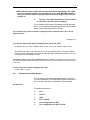
Figure below provides an illustration of IP Unnumbered
configuration.
5.7.6.3
IP Unnumbered with NAT
The configuration shown above requires each LAN PC to have a
public IP address (within a range given by the ISP) and does not
make use of Network Address Translation (NAT). However,
because each public IP address is normally available only at a cost
to the user, there may be cases where the customer has more LAN
PCs than available public IP addresses.
For example, a customer may obtain four public IP address from the
ISP for use with servers on the LAN (web server, mail server, etc.),
but may have 10 additional PCs that use private IP addresses in the
subnet 192.168.1.x, mask 255.255.255.0.
The user can configure NAT to enable these 10 PCs to access the
internet. This can be achieved by creating a virtual IP (VIP) LAN
interface on the modem with private IP address (say, 192.168.1.1,
mask 255.255.255.0). The user would then create a NAT rule
(NAPT flavor) to translate the PCs’ local IP addresses to the VIP IP
address. The following CLI commands create a rule of this type and
enable the NAT service:
- 43 -
create nat rule entry ruleid 1 napt lcladdrfrom 192.168.1.2 lcladdrto
192.168.1.254
modify nat global enable
5.8
Configuring the Operating Mode
The reference unit is preconfigured to boot up as a router. Once the
unit is running, however, you can use CLI commands to interactively
reconfigure the unit to run in either operating mode (router or bridge)
or to configure special features of routing mode, such as
simultaneous bridging and bridged IP.
For your own product, you can preconfigure the operating mode
(and other settings) by modifying the factory defaults file and using it
to create your own flash image. For complete information on this
process, refer to the Image Handling User Manual.
5.8.1
Bridge Mode
To change the reference unit’s operating mode to bridge mode:
create an EoA WAN interface without an IP address;
create the Ethernet LAN interface without an IP
address;
configure the EoA and LAN interfaces as bridge
ports; and
enable bridge mode.
Creating the EoA interface
Refer to section
Creating the Ethernet interface
Refer to section
Configuring bridge ports
Bridge ports can be created on the physical Ethernet interface (eth0), and on the EoA interfaces (eoa-0, eoa-1, etc.).
To enable bridging on the eth-0, usb-0, and eoa-0 interfaces, enter:
$ create bridge port intf ifname eth-0
$ create bridge port intf ifname eoa-0
- 44 -
To list all interfaces on which bridge ports have been created, enter:
$ get bridge port intf
Enabling bridging
To enable bridging, enter:
$ modify bridge mode enable
To disable bridging, enter:
$ modify bridge mode disable
To see whether bridge mode is enabled or disabled, enter:
$ get bridge mode
5.8.1.1
Bridge Forwarding Table
In bridge mode, the unit is a learning bridge, i.e., it automatically
learns the association between MAC addresses and interfaces. The
unit stores this information in the bridge forwarding table, which
maps each LAN host’s MAC address to one of the bridge’s
interfaces.
Displaying the bridge forwarding table
To display the bridge forwarding table, enter:
$ get bridge forwarding
Setting an entry’s timeout period
An entry remains in the bridge forwarding table for the duration
specified by the aging parameter. After an entry is deleted, the
bridge will relearn that entry the next time the associated host sends
any data across the bridge.
To set the aging parameter to 300 seconds, enter:
$ modify bridge info aging 300
- 45 -
To see the current value of the aging parameter, enter:
$ get bridge info
5.8.1.2
Static Bridge Entries
Because of the aging parameter, every entry is eventually deleted
from the bridge forwarding table (and later relearned), except for
static entries. Static entries are not affected by the aging
parameter; they never time out and are never deleted from the
bridge forwarding table.
Creating a static entry in the bridge forwarding table
To create a static entry in the bridge forwarding table that maps MAC address 0:1:2:3:4:5 to
a specific interface such as eth-0, enter:
$ create bridge static macaddr 0:1:2:3:4:5 ifname eth-0
5.8.1.3
MAC Address Conflicts in Bridge Mode
In bridge mode, the unit by default filters (i.e., does not forward) data
for a set of 17 reserved MAC addresses, per the 802.1d bridge
specification. These MAC addresses are 01:80:C2:00:00:00 through
01:80:C2:00:00:10.
Conflicts can arise if an application uses any of these reserved MAC
addresses (one such application is 802.1x Dialup). If this occurs, you
must override the default list of reserved MAC addresses, as follows:
Edit the text file resvmac.txt in createfi\TEFileSys\bridge.
Delete the address(es) that should not be filtered and save the file.
Run Createfi to create a new image.
Load the image into the unit, then bring up the unit in bridge mode.
When in bridge mode, the unit performs filtering as follows:
If resvmac.txt specified any MAC addresses, the unit filters all those addresses.
If resvmac.txt was left blank, the unit performs no filtering at all.
If resvmac.txt was omitted from createfi\TEFileSys\bridge, the unit will filter the default set
of 17 MAC addresses.
For information on Createfi, refer to the Image Handling User
Manual.
5.8.1.4
Spanning Tree Protocol
The Spanning Tree Protocol (STP) prevents the formation of loops
among interconnected bridges.
- 46 -
By default, STP is enabled on all bridge ports. It is recommended that STP be enabled whenever three or
more bridges are interconnected and at least one physical loop (multiple paths between two bridges)
exists.
Modifying STP on all ports
To configure STP parameters applicable to all ports, use the command:
$ modify stp global
Modifying STP on a specific port
To configure STP parameters for a specific interface such as eth-0, use the command:
$ modify stp port ifname eth-0
You must create the bridge port before you can use this command.
Disabling STP
To disable the STP ports, enter both of the following commands:
$ modify stp port ifname eth-0 disable
$ modify stp port ifname usb-0 disable
$ modify stp port ifname eoa-0 disable
5.8.2
WAN to WAN bridging
The unit does not allow WAN-to-WAN bridging, as this behavior may
not be desired by users in some configuration, for reasons such as
security or bandwidth constraint. However, it allows LAN-to-WAN
and WAN-to-LAN bridging. WAN-to-WAN bridging is enabled, by
default.
To disable bridging packets between WAN ports,
enter:
modify bridge mode wan2wan disable
To disable WAN-to-WAN bridging using the HTTP
interface, use the Bridging Menu.
5.8.3
Router Mode
If the reference unit is not currently operating in router mode, you
can change it to router mode as follows:
set the LAN interface as the default gateway for the
LAN hosts;
- 47 -
create one or more WAN interfaces (PPPoE, PPPoA,
EoA, or IPoA); and
configure one of the WAN interfaces as the default
route.
Making the LAN interface the default gateway
You can configure the IP properties on each LAN host to reflect the LAN interface IP
address as their default gateway. Or, if you are using the unit as a DHCP server, you can
configure the DHCP properties to automatically assign the LAN IP addresses.
Creating the WAN interfaces
PPP interfaces: refer to section
EoA interfaces: refer to section
IPoA interfaces: refer to section
Making the PPP Interface the Default Route
To make the PPP interface ppp-0 the default route, set the droute parameter to true while
creating the interface:
$ create ppp intf ifname ppp-0 lowif aal5-0 ppoe sname games droute
true
5.8.3.1
Simultaneous Bridging and Routing
In this special feature of router mode, the reference unit
simultaneously acts as a router for IP traffic and as a bridge for nonIP traffic. To configure the reference unit as a router with
simultaneous bridging and routing:
configure the unit as a router as described in section
but with at least one IP-enabled EoA interface with a static
default route;
configure the Ethernet interface and an IP- enabled
EoA interface as bridge ports; and
enable bridge mode.
Creating the IP-enabled EoA interface
- 48 -
Refer to section
Creating the Ethernet interface
Refer to section
Configuring bridge ports
To enable bridging on the eth-0, usb-0, and the eoa-0 interfaces, enter:
$ create bridge port intf ifname eth-0
$ create bridge port intf ifname usb-0
$ create bridge port intf ifname eoa-0
To list all interfaces on which bridge ports have been created, enter:
$ get bridge port intf
Enabling bridging
To enable bridging, enter:
$ modify bridge mode enable
To disable bridging, enter:
$ modify bridge mode disable
To see whether bridge mode is enabled or disabled, enter:
$ get bridge mode
5.8.3.2
Bridged IP
In this special feature of router mode, the reference unit functions as
a bridge over the WAN interface and as a router over the LAN
interface. To configure the reference unit as a router with bridged IP:
configure the unit as a router as described in section
but with at least one IP-enabled EoA interface
Creating the IP-enabled EoA interface
- 49 -
Refer to section
Creating the Ethernet interface
Refer to section
Configuring bridge ports
To enable bridging on the eth-0, usb-0, and the eoa-0 interfaces, enter:
$ create bridge port intf ifname eth-0
$ create bridge port intf ifname usb-0
$ create bridge port intf ifname eoa-0
To list all interfaces on which bridge ports have been created, enter:
$ get bridge port intf
Enabling bridging
To enable bridging, enter:
$ modify bridge mode enable
To disable bridging, enter:
$ modify bridge mode disable
To see whether bridge mode is enabled or disabled, enter:
$ get bridge mode
5.8.4
Bridge Router Autosense (BRAS)
The Bridge Router Autosense feature will be useful in the following
scenario. The unit is pre-configured completely, for the unit to run in
either routing mode or bridging mode. Basically the unit would have
both PPPoE and EoA interfaces pre-configured. When the unit is
plugged in to the user's network, it is able to detect the mode in
which it is required to operate. This means that, the user would be
able to use either the unit's PPPoE client, or one on the LAN PCs,
as the need may be, without having to configure anything on the
unit. The unit would be able to withdraw it's PPPoE client at run time
if it detects any PPPoE traffic.
- 50 -
5.8.4.1
Configuration details
When the unit boots, configured PPPs will try to come up as usual. If
PPPoE traffic is detected from the LAN end, then the PPPoE client
on the modem will get disabled. The PPPoE packet received from
the LAN will get forwarded to the WAN side, because of the
preconfigured bridge ports.
If later on, the user wants to switch to the unit's PPP, he just needs to re- enable the
PPPoE client on the unit using the following CLI command:
modify bras <selfppe restart>
This will bring up the unit’s PPPoE. Thereafter, starting the LAN
PPPoE client again, will disable the unit’s client.
To enable or disable the BRAS feature, the user can use the following CLI command:
modify bras enable | disable
A reboot is not required to switch back and forth between enabling
and disabling this feature.
5.8.5
Zero Installation PPPoE Bridge (ZIPB) Mode
Configuring the modem in the Zero Installation PPPOE Bridge or
ZIPB mode enables service providers to avoid installing a PPPoE
client on subscriber PCs as well as avoid running NAT on the
modem. ZIPB combines the advantages of routing and bridging
modes.
5.8.5.1
Advantages of the ZIPB mode
Configuring the modem in the ZIPB mode:
does not require you to install any software on
subscriber PCs
does not require you to run NAT on the modem
allows you to manage modem for both LAN and
WAN sides, because the modem has an IP address on
both LAN as well as WAN interfaces.
allows you to run Firewall/filtering feature on the
modem.
allows you to use bandwidth efficient PPPoA, on the
modem’s WAN interface.
- 51 -
5.8.5.2
ZIPB mode - operation details
LAN PCs get their global addresses through the DHCP server
functionality. If a PPP IP address is available to the unit, the LAN PC
gets this address on a DHCP request.
Initially, when PPP is not yet up, the IP address allocated to the LAN
PC comes from the Ethernet pool, and PPP is triggered to come up.
When the LAN PC sends a renewed request for an IP address
allocation, the unit checks if any PPP IP address is free to be
allocated. If a PPP IP address is free, then, it will send a NACK to
the renewal request for the Ethernet pool IP address. This will force
the LAN PC to go in to the DHCP discovery state. Now, when the
unit receives a fresh DHCP discovery message, it will allocate the
PPP IP address and simultaneously de- allocate the IP address
allocated from the Ethernet pool.
For proper functioning of ZIPB, PPP should be configured with the
‘startondata’ option. This will ensure that PPP comes up only when
the LAN PC is up and that PPP goes down when the LAN PC is
switched off.
The behavior of ‘startondata’ is different when ZIPB is enabled. With ZIPB enabled, PPP comes up only if
the LAN PC sends a DHCP request for an IP address, and not on any other data activity.
The unit remembers the PPP IP address even after PPP goes
down. The unit continues to allocate this same PPP IP address to
the LAN PC. So, the user can access the Internet the minute PPP is
up. He does not need to wait for IP address allocation, provided
PPP comes up with the same IP address.
If the PPP IP address is different from the previously allocated
address, it will send a ForceRenew message to the LAN PC. The
next time the PC tries to get an IP address, it will get the new PPP
IP address.
To enable ZIPB at the modem, enter,
modify zipb cfg enable
5.8.5.2.1
Management from LAN end
When the unit is working in ZIPB mode, the LAN side PCs get the
PPP IP addresses allocated to the modem using IPCP or DHCP. If
the PPP interface is not up, the PC gets an IP address from the
DHCP server pool 0. The DHCP pool has a small default lease and
clients will keep sending renew requests after 30 seconds.
Each request for renewing an IP address from DHCP pool 0, results in writing to NVRAM and more writes
to NVRAM. This reduces the NVRAM life.
- 52 -
LAN machines can access the modem in ZIPB mode, as they
would, in non-ZIPB mode, using the Ethernet IP address.
Instead of trying to access an IP address, the LAN side PC user should use the DNS relay capability of the
modem. Please refer to the chapter on DNS relay for details on this feature.
5.8.5.2.2
Management from WAN end
When in ZIPB mode, with the PPP link up, all requests coming to the
modem from the WAN end are passed on to the PC behind it, as the
PPP IP address of the modem is considered the IP address of the
PC behind the modem. The standard Telnet, FTP and HTTP
services on the PC behind the modem, run on ports 21, 20 and 80
respectively. However, if you want to access any of the telnet, ftp or
HTTP services on the modem, you can configure the ports to be
other than the standard ones used on the PC behind the modem.
To access the modem from the WAN end, using telnet or http, use
the PPP IP address allocated to the modem. The ports you will
specify during WAN- end access should be the same as those
specified for the modem in the nbsize command.
While configuring telnet and http ports, above, from both LAN and WAN ends, the user needs to
remember to use the same ports as those mentioned in the get nbsize command.
5.8.5.2.3
Use of ForceRenew in ZIPB mode
When configured in the ZIPB mode, the modem is able to detect
that the LAN PC is switched off, and it automatically brings down
PPP. When the LAN PC comes up again, the modem senses it, and
brings up PPP too.
ForceRenew, as defined in RFC 3203 is used in the ZIPB mode in
the following scenarios.
If a LAN client is up with an IP address from the Ethernet pool, and
the PPP interface comes up, a ForceRenew message is sent to the
client. When the client sends a renew, it is sent a NACK by the
server. The Client then sends a Discover and now it can be given
any of the free PPP IP addresses maintained by the DHCP server.
The DHCP server initiates ForceRenew for the following trigger
points:
ZIPB is enabled
ZIPB disabled
PPP Up trigger
5.8.5.3
Preconditions to configuring the modem in ZIPB mode
An Ethernet interface should be created. You
can use the following syntax,
create ethernet intf ifname eth-0 ip 192.168.1.1 mask 255.255.0.0
- 53 -
You need to create and enable a DHCP server pool
with poolId 0 and an Ethernet subnet with small lease
time. For example, you can use the following syntax.
create dhcp server pool poolid 0 start-ip 192.168.1.2 end- ip
192.168.1.5 mask 255.255.0.0 lease 60 mlease 120
Enable dhcp server, by entering,
dhcp server cfg enable
You should also configure PPP with startondata.
$ create ppp intf ifname ppp-0 ppoe sname test lowif aal5-0
droute true startondata
Configure the ftp, telnet and http ports to be different from the standard ports 23, 20 and
80 respectively, if you want to provide these services on the LAN PC as well.
5.8.5.4
Configuring ZIPB
You can either enable or disable the ZIPB mode on the modem. It is
disabled by default. You can set the mode by using either the default
configuration (factory defaults file) or CLI commands.
You can dynamically configure the modem to work in the ZIPB
mode. When disabled, the modem runs either in bridging or routing
mode. When enabled, it runs in the ZIPB mode.
Configuring using the factory defaults file
To enable ZIPB enter:
$ modify zipb cfg enable
Run the createfi utility and upload the image to flash.
Configuring using CLI
On the command line interface, use this command to enable ZIPB:
$ modify zipb cfg enable
The preconditions to configuring ZIPB, as mentioned in the section above, need to be met.
- 54 -
6 Viewing and Modifying DSL Information
The CLI enables you to configure various parameters that control
how data is transmitted on the DSL line. You can also view statistics
relating to the DSL line performance.
6.1
Modifying the DSL Configuration
You may need to modify various DSL parameters to ensure proper
operation of the reference design with your test equipment, or to
prepare your customer units for operation in the particular
environment in which they will be deployed. DSL-related information
can be modified using the following command:
$ modify dsl config <parameters>
The command parameters enable you to change a variety of
properties, including the DSL standard to which the firmware
complies and the DSL annex type. You can also start and stop
operation of the DSL loop and set various operating characteristics,
such as the coding gain due to Reed- Solomon or trellis coding, the
level of framing overhead, and the power attenuation in dB.
Several examples follow. A complete list of parameters and their
descriptions is provided in the CLI Reference Manual.
Modifying the DSL configuration
To change the DSL standard to G.dmt (G.992.1), enter:
$ modify dsl config gdmt
To change the DSL annex to Annex C, enter:
$ modify dsl config annexc
To enable (default) or disable the operation of the DSL loop, enter:
$ modify dsl config loop start
$ modify dsl config loop stop
Viewing the DSL configuration
- 55 -
To view current DSL configuration information, enter:
$ get dsl config
6.2
Viewing DSL Parameters and Statistics
You can use the following commands to view a variety of nonmodifiable DSL parameters and performance statistics. For a
complete list of all parameter values for all the following commands,
see the CLI Reference Manual.
Viewing DSL parameters
To view DSL parameters, enter the following command:
$ get dsl params
The output displays static DSL information such as the vendor ID and serial number, and
calculated values such as far- and near-end RS errors, the signal-to-noise ratio, the calculated
line attenuation, and other statistics.
Viewing DSL statistics
To view the number of errored, severely errored, and unavailable seconds in the past 15minute interval and in the past 24 hours, type the following command:
$ get dsl stats curr
To view the number of errored, severely errored, and unavailable seconds for eight 15minute intervals, starting with four intervals ago (i.e., statistics for the intervals from 1
hour ago to 3 hours ago), enter:
$ get dsl stats hist 8 4
The display also shows the number of intervals in which valid data was transmitted. You can
specify up to 96 past intervals to display.
To view near- and far-end errors counts relating to Reed-Solomon, CRC, and other errors
types accumulated since the last reboot, enter:
$ get dsl stats cntrs
To view local and remote transmission failures accumulated since the last reboot, enter:
$ get dsl stats flrs
- 56 -
The output displays loss-of-signal defects (LOS), severely errored frame defects (SEF), no-cell
delineation errors, and loss-of-cell delineation errors for the data stream.
Resetting DSL statistics
The DSL counters and failure statistics accumulate starting from the last reboot. You can
use the following commands to reset these statistics to zero without rebooting:
$ reset dsl stats flrs
$ reset dsl stats cntrs
- 57 -
7 Configuring IP and Routing Management
This chapter shows you how to configure routes on the modem and
on the LAN hosts.
Before you begin this chapter, configure the WAN and LAN interfaces as described above.
7.1
Configuring Routing on LAN Hosts
In routing mode, because the unit acts as the gateway for the LAN
hosts, the LAN hosts should be configured to use the LAN IP
address as their default gateway.
7.2
Configuring Routes
Of the WAN interfaces, the PPP, EoA, and IPoA interfaces are IPenabled, i.e., can have IP addresses. A PPP, EoA, or IPoA interface
can therefore be used as the default route for the unit itself.
Configuring a PPP interface as the default route
The create ppp intf command has a droute parameter that, when set to true, makes the
interface the default route. In this case, PPP automatically creates the default route entry,
where the default gateway address is the IP address of the other end of the PPP interface.
Only one PPP interface can be made the default route using droute.
There can be only one default route on the modem.
You can use the create ip route command to create other,
non- default routes also. These are called static routes. The ip and
mask parameters indicate the destination for which the route is
being created. If the mask is 255.255.255.255 then the route is
towards a single host whose IP address is given by the ip
parameter. Any other value of the mask indicates that the route is
towards a subnet, the subnet address being determined by masking
the ip parameter with the given mask.
Creating a static route
To create a static route to the subnet 172.25.0.0 (mask 255.255.255.0), via the gateway
10.2.1.1, enter:
$ create ip route ip 172.25.0.0 mask 255.255.255.0 gwyip 10.2.1.1
- 58 -
Be sure to verify that your modem can reach the gateway. This can be done beforehand using
the ping command, e.g., ping 10.2.1.1.
A dynamic route is one created automatically by the modem, either
when you create an IP-enabled interface, or by learning through
RIP.
To see the current routes, both static and dynamic, enter:
$ get ip route
Deleting a route
To delete a route, enter:
$ delete ip route ip 172.25.0.0 mask 255.255.255.0
Modifying an IP route
To modify an IP route, delete the existing route using the delete
ip route command, then recreate the route using the create ip
route command.
Suppose you create a static route to subnet 172.25.0.0 via gateway 10.2.1.1. To modify the
route to use a different gateway, say 20.1.1.1:
First delete the existing entry by entering:
$ delete ip route 172.25.0.0 mask 255.255.255.0
Next, recreate the route with the new gateway address by entering:
$ create ip route ip 172.25.0.0 mask 255.255.255.0 gwyip 20.1.1.1
7.3
Routing Mode
Routing (or more appropriately, forwarding) is enabled by default. It
can be disabled using the modify ip cfg command.
To disable IP forwarding on the modem, type the command:
$ modify ip cfg forwarding disable
- 59 -
To see the current state, type the command:
$ get ip cfg
7.4
RIP
Routing Information Protocol (RIP) is a dynamic routing protocol
typically used inside the organization to exchange routes between
various routers within the organization. The modem’s RIP is an
implementation of RIPv2 with compatibility with RIPv1 and can be
configured to run as either RIPv1, RIPv2, or RIPv2-with-RIPv1
compatibility mode.
7.4.1
RIP Global Configuration
To enable or disable RIP on the IAD use the command :
$ modify rip global
The command also allows you to modify RIP timing parameters
such as updatetime which is the frequency at which the modem
broadcasts its routes, and agetime which is the time after which the
modem would delete a route for which no updates have been
received.
To see the current state and currently active global configuration, use the command:
$ get rip global
7.4.2
RIP Interface Configuration
To configure RIP on an IP enabled interface with the desired configuration, use the create
rip intf command :
$ create rip intf ifname ppp-0 metric 1 send rip2 receive rip2
senddefroute enable recvdefroute enable auth text abcd
The above command enables RIP on ppp-0 interface.
The send and receive parameters indicate that RIPv2 is to be
used for both sending and receiving RIP updates. The
senddefroute parameter simply tells whether the modem should
send updates for default routes or not. Similarly, the
recvdefroute parameter tells whether the modem should process
updates for default routes received from other routers or not. The
auth parameter says that RIP authentication is to be provided using
the clear text password abcd. Routers sending RIP updates to the
modem on this interface must include this password in their
messages. The same password is also used by the modem when it
- 60 -
sends out RIP updates to other routers on this interface. If no
authentication is required, the auth parameter is set to none. In
case of RIPv1, auth must be set to none.
The metric is a kind of path cost associated with the interface. The higher the metric, the costlier it is to use that
interface to get to a particular destination.
When a router sends its routing updates to the modem it associates
a metric value with each route. Suppose the modem receives RIP
updates for routes to the same destination A from two of its
interfaces, ppp-0 and ppp-1. The metric in the messages received
on the two interfaces is, say, the same,3. Further suppose that we
created the RIP interface on ppp-0 with the metric 1 and on ppp-1
with the metric 2. Now when the modem tries to decide whether to
use ppp-0 or ppp-1 to reach the destination A, it adds the metric
given during the create rip intf command to that update
received in the RIP message. So reaching A via ppp-0 has a metric
cost of 3 + 1 = 4, while reaching A via ppp-1 has a metric cost of 3 +
2 = 5. The route chosen finally is the one with the minimum metric
cost, i.e. ppp- 0. The metric associated with the RIP interface is also
used while sending RIP updates to neighboring routers. For a route
received on ppp-0 with metric 2, the update to a router connected to
ppp-1 would contain the metric calculated as follows Original metric + metric of ppp-0 = 2 + 1 = 3
The metric can be any number between 1 and 15. Setting the metric
to 15 effectively disables that interface for IP traffic, i.e. routes using
that interface are deleted from the routing table.
To modify RIP parameters, use the command:
$ modify rip intf
To view the current configuration, use the command:
$ get rip intf
7.5
IGMP
The Internet Group Management Protocol (IGMP) is used by
multicast- enabled hosts to tell routers on their LAN that they want to
receive multicast packets. Multicast routers use IGMP messages to
learn the presence of multicast groups on their LAN so that they can
forward relevant multicast packets to them. The modem supports
IGMP version 1.0 and version 2.0.
- 61 -
Creating IGMP interfaces is useful only when the unit is configured in routing or ZIPB mode. When the
unit is configured for routing and bridging simultaneously, then all multicast packets will go through
routing path —and not through the bridging path — if the IGMP interface is created as described in this
section. If you require that multicast packets go through bridge mode only, do not create an IGMP
interface on the unit.
IGMP is enabled on the modem by configuring IGMP router and
host interfaces.
IGMP router interfaces are typically the LAN side
interfaces, and these can be multiple.
The IGMP host interface is typically one of the WAN
side interfaces (PPP, EoA or IPoA); there can be only one
IGMP host interface.
The modem listens to IGMP reports on its router interface(s),
consolidates them, and forwards the consolidated reports out its
host interface, thereby acting as an IGMP proxy agent for its LAN
hosts. The reports generated on the LAN also help the modem learn
what groups are currently active on each of its LAN interfaces. This
information can be viewed using the get igmp groups command.
If a packet is received for a group which the modem knows is active
on at least one of its router interfaces, it forwards the packet out that
interface.
The IGMP version can be configured individually for each of the
modem’s IGMP-enabled interfaces. As IGMPv2 can fall back to
IGMPv1, it is preferable to configure all interfaces with IGMPv2; the
modem will still be able to communicate with an IGMPv1-compliant
LAN PC or uplink router.
Configuring IGMP router interface on eth-0
To configure an IGMP router interface on eth-0 with the default values, enter:
$ create igmp intf ifname eth-0 router
You can add these parameters to the command (see the example
that follows).
query interval: the interval at which the modem
periodically queries the hosts for currently active groups
maximum response time (IGMPv2 only): the amount
of time a host has to respond to a query
last member query interval (IGMPv2 only): After
receiving a “leave group” message from a host, the
modem will send a query to determine if other hosts
remain in the group, and wait for responses. This
parameter determines the amount of time the modem
waits for responses.
- 62 -
For any IGMPv2 router interface, if you set the last member query interval as 0 seconds, then as soon as
an IGMP “leave group” message is received from any LAN side host, the group will be detached from that
router interface. This means that the modem will not send an IGMPv2 group- specific query to find other
LAN hosts still interested in receiving data for this multicast group.
If you know that there is only one LAN host for a group particular group (e.g., if an IGMP-compliant video
set-top box is connected to the modem), set this parameter to 0 so that the modem will detach the group
immediately.
robustness indicator: a whole number used to
multiply the specified query and response intervals, or to
set the number of repeated queries that must be sent out
when determining whether any hosts remain in a group.
Specify a higher number when the network has a greater
tendency to lose messages.
Configuring an IGMP router interface with parameters
The following command configures an IGMP router interface on eth0 with version IGMPv2, a last member query interval of 1 second, a
robustness indicator of 3, and a query interval of 60 seconds:
$ create igmp intf ifname eth-0 router version igmpv2 lmqinterval 1
robust 5 qinterval 60
Configuring an IGMP host interface on ppp-0
To configure an IGMP host interface on ppp-0 with the default values, enter:
$ create igmp intf ifname ppp-0 host
To configure an IGMP host interface on ppp-0 with IGMPv1, enter:
$ create igmp intf ifname ppp-0 host version igmpv1
Viewing IGMP groups
To see which groups are currently registered on the modem's IGMP router interfaces,
enter:
$ get igmp groups
If, for example, the command output reports group 224.1.1.1 on the eth-0 and usb-0 interfaces,
then when a packet with the destination of 224.1.1.1 is received on the IGMP router interface, it
will be forwarded to the eth-0 and usb-0 interfaces.
- 63 -
Deleting IGMP interfaces
To delete an IGMP host interface on eth-0, enter:
delete igmp intf ifname eth-0
To delete an IGMP host interface on ppp-0, enter:
delete igmp intf ifname ppp-0
- 64 -
8 Virtual Private Network
An internet-based virtual private network (VPN) uses the open,
distributed infrastructure of the Internet to transmit data between
corporate sites. This chapter explains how the modem uses the
Layer 2 Tunneling Protocol (L2TP) to provide the benefits of a VPN.
8.1
Overview
Why VPNs?
Businesses today are faced with supporting a broader variety of
communications among a wider range of sites even as they seek to
reduce the costs of their communications infrastructure. Employees
are looking to access the resources of their corporate intranets while
they are mobile, or from customer sites. Businesses are finding
traditional solutions to wide- area networking between the main
corporate network and the branch offices, inflexible and
expensive.VPNs using the Internet have the potential to solve many
of these business networking problems. VPNs allow network
managers to connect to remote branch offices and project teams to
the main corporate network, economically, while providing remote
access to employees without increasing the in-house requirements
for equipment and support.
How a VPN functions
Organizations using Internet VPNs set up connections to the local
connection points of their ISPs and let the ISPs ensure that the data
is transmitted to the appropriate destinations via the Internet, leaving
the rest of the connectivity details to the ISP’s network and the
Internet infrastructure.
In VPNs, connections are set up according to organizational needs.
The network is formed logically, regardless of the physical structure
of the underlying Internet. Unlike leased lines used in traditional
corporate networks, VPNs do not maintain permanent links between
the end points that make up the corporate network. Instead, a
connection is created only when it is required between two points.
When the connection is no longer required, it is torn down, making
the bandwidth and other network resources available to other users.
L2TP for VPNs
- 65 -
These connections or tunnels are set up between the remote client
and the corporate network it is trying to access. The client initiates
the creation of the tunnel in order to exchange traffic with the
corporate network. To do so, the client uses special client software,
which uses L2TP, to communicate with the gateway protecting the
LAN.
L2TP is one of the various protocols suggested for creating VPNs
over the Internet. L2TP uses PPP to provide dial-up access that can
be tunneled through the Internet to a site. L2TP uses the
authentication mechanisms within PPP, because it uses PPP for
dial-up links. L2TP also supports PPP’s use of the extensible
authentication protocols for other authentication systems.
The modem-based VPN service is actually an add-on software that
is a low-cost solution for client to LAN connections. This can run on
existing servers and share server resources.
8.2
L2TP
The Layer 2 Tunneling Protocol (L2TP) enables the user to connect
to the corporate server directly, while using the local ISP. The user
of a PPP session gets authenticated by the corporate server. This
cuts down on costs that the user would have otherwise incurred on
leased lines for branch offices or remote users.
The modem is a Customer Premises Equipment (CPE) used for
transportation of data over Digital Subscriber Line (DSL). The
modem uses Asynchronous Transfer Mode (ATM) technology over
DSL to transport data to its counterpart at the Central Office. The
software for the modem implements the protocol stack of ATM and
its adaptation layers. In addition to this, the modem incorporates
routing and bridging support for data protocols. Hence, all software
components such as the IP stack and requisite drivers, such as the
Ethernet driver, are also included.
L2TP is a tunneling protocol used for tunneling PPP packets through
IP networks. In an xDSL environment, user ATM PVCs extend from
the CPE to a centrally located NAS function. L2TP tunnels originate
from the CPE and terminate on the LNS at the corporate servers
connected to the Internet. The main application of this protocol is in
Virtual Private Dial in Networks, providing access to corporate
networks from mobile and remote users, and interconnecting
various corporate offices together for access across the globe.
The diagram below shows the user or the Client connected to a
LAN, talking to the modem installed at the CPE end. The modem
creates a tunnel through the ISP to the network server of the
corporate office, for gaining remote access. Here, the modem
functions a the L2TP access client (LAC), creating the tunnel to the
LAN network server (LNS), sitting at the corporate office router. The
- 66 -
link PPP-2 is first used to connect to the ISP. IPoA, EoA are
interfaces that could also be used for this link. The link PPP-1, that
connects the modem to the corporate server, uses L2TP.
Client-Corporate Office Connection using L2TP
L2TP Tunnel
A tunnel exists between an LAC-LNS pair. The Tunnel consists of a
Control Connection and zero or more L2TP Sessions. The tunnel
carries encapsulated PPP datagrams and Control Messages
between the LAC and the LNS.
L2TP Session
The LNS and LAC maintain state for each call that is initiated or
answered by an LAC. An L2TP Session is created between the LAC
and LNS when an end-to-end PPP connection is established
between a Remote System and the LNS. Datagrams related to the
PPP connection are sent over the Tunnel between the LAC and the
LNS. There is a one-to-one relationship between established L2TP
Sessions and their associated Calls.
The L2TP protocol manages the tunnel in a way that makes it
transparent to the PPP session inside it. L2TP clients are like "dialup" users, and L2TP servers are like access concentrators or
modem banks. Once the connection is "dialed", authenticated, and
connected, data starts to flow through the tunnel in much the same
- 67 -
manner as a modem dial-up, except that the call is placed through
the Internet (IP network) instead of the PSTN (telephone network).
If the tunnel server is on the corporate LAN, all branch office LANs
can connect to the centrally located server in order to talk to each
other. The user is connected to a LAN talking to the modem at the
CPE. The modem creates a tunnel through the ISP to the network
server of the corporate office in order to gain remote access. Here,
the modem acts as a L2TP access client (LAC), creating the tunnel
to the L2TP Network Server (LNS), at the corporate office router.
8.3
Configuration details
Configuring number of sessions over an L2TP tunnel
The maximum sessions over an L2tp tunnel can be configured using
the size command in the following manner:
size maxl2tpsessionpertunnel 2 maxl2tptunnel b
The default value for the maximum number of L2TP tunnels is 1,
and the maximum number of sessions possible over an L2tp tunnel
is 1.
Modifying L2TP global configuration
To modify L2TP global configuration, enter:
modify l2tp global config timeout 180
The timeout value is specified in seconds. You can also specify the timeout value as infinite. If the user
has configured the idle timeout (idletimeout) as infinite and the value for global config timeout is also set
to infinite then the tunnel will never come down. This is because, the peer does not send a response to a
control message, or , the upper PPP link goes down due to inactivity. The user should take care that
these timers should not have infinite values.
Getting global information on L2TP tunnel configuration
To get L2TP tunnel global configuration information, enter:
get l2tp global config
Getting L2TP global information
- 68 -
To get L2TP global information such as protocol Version and Vendor name, enter:
get l2tp global info
Creating L2TP tunnel
To create an L2TP tunnel, enter:
create l2tp tunnel config ifname l2t-0 localip 178.10.10.10 remoteip
178.10.11.10 start authtype simple secret passwd hellointerval 300
idletimeout num 100 crws 5 maxretx 10 maxretxtimeout 10 payloadseq
always transport udpip initiator local localhostname titanium
remotehostname columbia
While creating an L2TP tunnel, peers are authenticated, either in a Simple mode, or in a Challenge mode.
While creating a tunnel, if the 'initiator' type is LOCAL then the localip and remoteip fields in the command
are mandatory. If the initiator type is REMOTE then localip is mandatory while the remoteip is optional.
Deleting L2TP tunnel
Before deleting an L2TP tunnel it is necessary to delete all sessions
above that tunnel, or else the tunnel deletion fails.
To delete a L2TP tunnel, enter:
delete l2tp tunnel config ifname interface-name
Tunnel Initiator Modes
A tunnel can be created with one of the two initiator modes - LOCAL
or REMOTE.
When the tunnel is created with initiator as Local, the first message
(SCCRQ) for the process of tunnel establishment is sent to the peer
only on receiving the start tunnel trigger.
When the tunnel is created with initiator as Remote, a dormant state
is evoked, and the first message for the process of tunnel
establishment has to be sent by the peer.
Getting information on L2TP tunnel
- 69 -
To get information on one L2TP tunnel, or, all tunnels, enter:
get l2tp tunnel config ifname l2t-0
Modifying L2TP tunnel configuration
To modify L2TP tunnel configuration, enter:
modify l2tp tunnel config
ifname interface-name
localip local-ip-address
localhostname local-host-name
remoteip remote-ip-address
remotehostname remote-host-name
start|stop
[authtype
simple|challenge|none]
[secret tunnel-secret]
[hellointerval hello-interval]
[idletimeout {infinite|{num <decValue>}]
[crws contol-recv-windowsize]
[maxretx max-retransmission]
[maxretxtimeout max-retransmission-timeout]
[payloadseq
never|always}]
[transport udpip]
[initiator local|remote]
[enable|disable]
- 70 -
Starting and Stopping Tunnels
A Tunnel is created with two options START and STOP.
When the tunnel is created using the start option, creation and
establishment of tunnel happens simultaneously. If you create a
tunnel using the stop option, you can decide to start the tunnel later.
To stop an L2TP tunnel, issue the Stop Tunnel command. An L2TP
peer can also stop the tunnel by sending a StopCCN message.
Creating PPP Session over L2TP
You can create a PPP session over an L2TP tunnel in any one of
the three following modes.
Start - In this mode, the PPP session is created and
started simultaneously.
Starton data - In this mode, a PPP session is created
but not started till the data activity over that session starts.
Stop - In this mode, a PPP session is created with stop
option and can be started later.
To create a PPP session over L2TP, enter:
create ppp intf ifname ppp-1 start lowif l2t-0 L2TP usedhcp false
outside
Creation of PPP session fails if the lower layer (L2TP tunnel) doesn't exists.
Establishing and Ending Sessions
Once the tunnel is established, the process of establishment of
L2TP session over this tunnel also begins, if there are PPP sessions
configured with the lower layer as L2TP. Stopping an L2TP tunnel
brings down the L2TP tunnel and all the sessions over that tunnel.
When the user stops the PPP session over an L2TP session by
entering the following command, the particular L2TP session stops.
The command is
modify ppp intf ifname ppp-0 stop
Inactivity timer in lower layer PPP
When the link to the ISP is lost due to inactivity timer, L2TP brings
down all the tunnels configured with that IP address and all the
- 71 -
sessions over those tunnels are also torn down. Whenever the link
is restored, L2TP starts the process of establishment of all the
tunnels, which are configured with that IP address. The process of
establishment of all the sessions for those tunnels also begins once
the tunnel is established.
When the link comes up after going down, it should come up with the fixed IP address. If the link comes
up with an IP address which does not belong to the list of IP addresses configured for any of the tunnels,
then the tunnel that has gone down due to the link going down, will not come up.
Getting L2TP tunnel statistics
To get L2TP tunnel status and statistics for a particular tunnel interface, enter:
get l2tp tunnel stats ifname l2t-0
To get the same information for all L2TP sessions omit the ifname parameter.
Getting L2TP UDP statistics
To get L2TP UDP statistics, enter:
get l2tp udp stats l2t-0
Getting L2TP session statistics
To get L2TP session status for a particular PPP/ PPPoE session interface:
get l2tp session stats pppifname ppp-o
To get the same information fof all L2TP sessions omit the ppifname parameter.
Resetting L2TP Session statistics
To reset L2TP session statistics for a L2TP session for particular PPP interface, enter:
reset l2tp session stats pppifname ppp-0
Resetting L2TP tunnel statistics
To reset L2TP tunnel statistics for a particular tunnel interface, enter:
reset l2tp tunnel stats
- 72 -
8.4
L2TP Traps
L2TP sends traps for:
Tunnel establishment - This trap is generated when
the tunnel establishment with the peer is successful.
Tunnel down - This trap is generated when the tunnel
goes down due to stop tunnel command from user, or , due
to stop tunnel message from peer.
Session establishment - This trap is generated when
L2TP session is established successfully.
Session down - This trap is generated when an L2TP
session goes down.
- 73 -
9 Configuring DNS Relay
This chapter describes the commands for configuring the unit as a
DNS relay server.
9.1
Overview of DNS Relay
PCs on a LAN can set the IP address of the unit as the DNS server.
The Titanium unit will thus act as a DNS relay server and forward the
requests received from the PCs on the LAN to the actual DNS
servers, whose addresses have been learned from PPP. If the PPP
connection is not available (because of inactivity) at the time a DNS
request is received from the LAN, the PPP link will start
automatically. All the responses received from the DNS server will
be forwarded to the LAN PCs.
When the unit is configured as a DNS relay server, a user will not
need to change the DNS server IP address on their PC whenever
their ISP changes DNS servers, or when the user connects to a
different ISP.
9.2
Configuration Details
Enabling/Disabling DNS Relay
To enable or disable DNS relay, enter:
modify dns relay cfg [enable|disable]
Displaying Current Status
To display the current DNS relay statistics, enter:
get dns relay cfg
- 74 -
10Configuring DHCP Server and DHCP Relay
This chapter describes the commands for configuring the unit as a
Dynamic Host Configuration Protocol (DHCP) server, DHCP relay
agent, and DHCP client.
As a DHCP server, the unit maintains a pool of IP
addresses and distributes them to LAN hosts whenever
they are switched on.
As a DHCP relay agent, the unit forwards requests
for IP addresses from LAN hosts to a DHCP server (often
at the ISP’s location), and then returns the IP information
from the DHCP server to the hosts.
If the LAN uses its own DHCP server, then the LAN
interface on the unit can be configured as a DHCP client
of that server.
10.1 Default DHCP Configuration on the Titanium Reference Unit
By default, the Titanium reference unit is configured as a DHCP
server, with two pools of IP addresses. The following commands are
included in the default configuration file to set this configuration:
$ create dhcp server pool start-ip 192.168.1.2 end-ip 192.168.1.13
mask 255.255.255.0 gwy 192.168.1.1 enable
$ modify dhcp server cfg enable
The first line creates a single pool of IP addresses from 192.168.1.2
through 192.168.1.13 for distribution to up to 12 LAN hosts.
For the unit to operate as a DHCP server, LAN hosts must be configured to accept IP information
dynamically.
For more information about the default configuration see above.
10.2 Configuring Unit as DHCP Server
The two commands used in the default configuration provide the
basic instructions for configuring the device as a DHCP server. This
section explains those commands in detail and describes additional
commands and parameters you can use in your own configuration.
- 75 -
10.2.1 Creating DHCP Pools
A DHCP pool is a range of IP addresses made available on a server
for distribution to LAN hosts.
Creating a Basic DHCP Pool
To create a basic DHCP pool, enter:
$ create dhcp server pool start-ip 192.168.1.2 end-ip 192.168.1.13
mask 255.255.255.0
This command configures a pool of 12 IP addresses, from 192.168.1.2 to 192.168.1.13. The
mask indicates that this pool is applicable to the subnet 192.168.1.0.
The IP addresses specified in the pool must belong to same subnet as the physical ethernet interface or
one of the virtual ethernet interfaces.
Viewing Pools
To see the pool(s) you have created, along with other configurable parameters, enter:
$ get dhcp server pool
In addition to specifying the address ranges and network mask, you
can add parameters to the create command, to:
Assign a specific ID number to the pool (if not
specified, the next sequential number will be assigned
by default, starting from 0 as first pool).
Specify a lease period, which identifies how long
computers can use a particular IP address before it is
returned to the address pool (if not specified, the lease
period is set to 1 day by default)
Specify a low threshold, which determines when the
unit will send an alert that the available pool of
addresses is getting low.
Specify a domain name for hosts that receive
addresses from this pool (for the administrator’s
reference).
Specify IP addresses that hosts should use to
access various network servers (such as DNS, WINS,
POP3 servers).
Enable or disable the pool. IP addresses cannot be
assigned from a disabled pool, but the configuration
remains on the system for future activation.
- 76 -
Assigning a Pool ID
You can configure multiple pools for assignment to different subnets
on the LAN. Each pool is distinguished by a pool id. If the pool id is
not specified in the create command, the pool is assigned the first
available pool id.
To assign a particular pool id number include it in the command:
$ create dhcp server pool poolid 2 start-ip 192.168.1.3 end- ip
192.168.1.34 mask 255.255.255.0
Specifying a Lease Period
The DHCP server allocates IP addresses to clients for a specified
duration, called the lease. You can specify a default lease period
and a maximum lease period for each DHCP pool. If you do not
specify a lease period when you create the pool, the default lease
period is set to 2592000 seconds (30 days) and the maximum lease
is set to 31536000 seconds (365 days).
When the lease period expires, the client may again request an IP
address from the DHCP server. The client can request an address
for a specific lease duration. The server will grant the request if the
duration is less than the maximum lease period configured for the
pool. If the client request does not specify a lease duration, the
server assigns an IP address for the default lease period.
To specify a lease period of one day, for example, create pool as follows:
$ create dhcp server pool poolid 2 start-ip 192.168.1.2 end- ip
192.168.1.13 mask 255.255.255.0 dlease 86400 mlease 4294967295
If you do not want to limit the lease period, you can set the default
lease and maximum lease periods to the maximum of 4294967295
seconds (greater than 136 years).
Specifying a Low Threshold Value
Each DHCP pool has a low threshold value associated with it.
Whenever the number of available IP addresses in the pool drops
below this threshold, the server produces the low threshold hit trap.
This trap indicates that available addresses from the pool may soon
be exhausted and hosts coming up on the LAN will not be allocated
IP addresses dynamically.
By default, the low threshold parameter is given a value of 0. Since
the number of available addresses can never fall below 0, this
- 77 -
means that the trap will be generated only if you have specifically set
the low threshold to a non-zero value.
To specify the low threshold value, type:
$ create dhcp server pool poolid 2 start-ip 192.168.1.2 end- ip
192.168.1.13 mask 255.255.255.0 lthres 3
Enabling and Disabling Pools
By default, when you create a new pool it is enabled for use. You
can disable a pool if you do not want to use it currently, but want to
retain the information for future use.
To disable a pool, type the command:
$ modify dhcp server pool poolid 0 disable
To re-enable the pool, type the command:
$ modify dhcp server pool poolid 0 enable
10.2.2 Excluding Addresses from a Pool
If you do not want particular addresses to be assigned to LAN hosts,
you can add these to a pool exclusion table.
To mark an address as unusable (for example 192.168.1.13) from an existing pool, type the
command:
$ create dhcp server exclude ip 192.168.1.13
To remove the entry from the pool exclusion table and make it available for use, type the
command:
$ delete dhcp server exclude ip 192.168.1.13
To view the pool exclusion table entries, type the command:
$ get dhcp server exclude
- 78 -
10.2.3 Modifying and Deleting Pools
You can modify the lease and other configurable parameters using
the modify command or by giving the relevant parameters directly
in the create command.
Modifying Pools
To modify a DHCP pool, use the command:
modify dhcp server pool poolid 0 [parameter value]
For example, to modify the DNS server assigned to DHCP clients, use:
$ modify dhcp server pool poolid 0 dns 192.168.1.11
The modification will be reflected on the host whenever it reboots next and gets its address and
other parameters from the modem.
Deleting Pools
To delete a pool with pool id 2, use the command:
$ delete dhcp server pool poolid 2
If you delete a pool or modify its settings while IP addresses are currently allocated from the pool, the
hosts will continue to use the allocated IP addresses with the original settings, till the next renewal.
10.2.4 Creating Static DHCP Assignments
The DHCP server will attempt to assign the same address to a host
each time the host boots; however, this may not always be possible.
A host may be assigned an IP address, different from the one it
previously used, depending on the available addresses. In some
situations, it may be important that the DHCP server always assigns
the same IP address to a particular host.
The unit’s static hosts table enables you to create a permanent oneto-one association between a host and an IP address. On the LAN,
a particular host is uniquely identified by its MAC address. A static
host entry stores the association between the MAC address and a
fixed IP address, as in the following example.
Adding an Entry to the Static Hosts Table
- 79 -
To create an entry in the static hosts table that associates the MAC address 00:80:48:CB: B8:
83 with the fixed IP address 192.168.1.2, type the command:
$ create dhcp server host ip 192.168.1.2 mask 255.255.255.0 hwaddr
00:80:48:CB:B8:83 dlease 4294967295 mlease 4294967295
The lease periods carry the same meaning as for a pool. You can
set them to 4294967295 if you do not want to limit the lease period.
The hardware address parameter (hwaddr) refers to the MAC
address or the Ethernet address. The specified IP address is
reserved for the host regardless of whether the host is currently
switched on. The IP address will not be allocated to any other host.
Viewing the Static Hosts Table
To see the details of all configured static hosts, type the command:
$ get dhcp server host
Deleting an Entry from the Static Hosts Table
To delete a static host entry that is no longer required, use the command:
$ delete dhcp server host ip 192.168.1.3
To delete all static hosts, type the command without specifying an IP address:
$ delete dhcp server host
After you delete the entry, the client will continue to use the IP address, but only for the next renewal.
10.2.5 Enabling the DHCP Server
After configuring DHCP pools, you must enable the DHCP server.
In the default software setting, DHCP server is disabled. However, on your reference board, DHCP has
been enabled.
To enable the server, type the command:
$ modify dhcp server cfg enable
To disable the DHCP server, type the command:
$ modify dhcp server cfg disable
- 80 -
To see the current state of the server, type the command:
$ get dhcp server cfg
10.2.6 DHCP- DNS Relay Interaction
The DHCP server indicates the DNS Server addresses to DHCP
clients in the following manner.
If the primary/secondary DNS addresses are provided as part of the pool configuration
(using the DNS and SDNS parameters in the create/ modify dhcp server pool commands),
then these are indicated to the client.
If the DNS and SDNS addresses are not specified in the pool configuration, then one of the
following cases will arise.
If the DNS relay is enabled, the DHCP server gives the modem’s LAN IP address as the
DNS server address to the clients.(The actual DNS servers are learned by the
modem, dynamically, via the PPP link. These can be viewed using the get dhcp
server cfg command.)
If the DNS relay is disabled, the DNS addresses indicated to the client are the ones that
are dynamically learned from the PPP link. That is, they are the same as the ones
displayed by the get dhcp server cfg command.
10.2.7 Viewing DHCP Server Address Assignments
Once the server starts assigning IP addresses to clients, you can
see the currently allocated addresses.
To see the currently allocated addresses, type the command:
$ get dhcp server address
10.3 Configuring DHCP Relay
To use the ISP’s DHCP server, you can configure the unit to act as
a DHCP relay agent. As a relay agent, the unit forwards DHCP
requests from the LAN hosts on to the ISP. The ISP’s DHCP server
then sends back IP addresses and other configuration information,
which the unit forwards to the LAN hosts.
To configure the unit as a DHCP relay agent, you first specify the
interfaces on which the unit will listen for DHCP requests and
responses. Then, you enable DHCP relay mode.
10.3.1 Configuring the DHCP Relay Interfaces
The unit’s LAN interface must be enabled for DHCP relay in order to
receive requests from the LAN hosts for IP information. If multiple
LAN interfaces are defined on the unit, the DHCP relay service can
be enabled on each interface simultaneously.
- 81 -
To receive responses from the ISP, the unit’s WAN interface must
also be enabled for DHCP relay. The WAN interface could be a
PPP, EoA, or an IPoA interface.
Specifying the DHCP Relay Interfaces
To specify that the unit will receive DHCP requests on the LAN (eth-0) interface and the
WAN (ppp-0) interface, enter these commands:
$ create dhcp relay intf ifname eth-0
$ create dhcp relay intf ifname ppp-0
Viewing DHCP Relay Interfaces
To see all the interfaces on which DHCP relay is enabled, type the command:
$ get dhcp relay intf
10.3.2 Specifying the DHCP Server IP Address
You can specify the IP address of the DHCP server by modifying the
DHCP relay configuration. It is not mandatory to configure this
address. The ISP should be able to route the request to the
appropriate server. If you assign the DHCP server IP address, you
should also define a route in the unit’s IP routing table.
Specifying the DHCP Server IP address
To specify the IP address of the ISP’s DHCP server (202.64.23.4 in this example), use the
command:
$ modify dhcp relay cfg ip 202.64.23.4
10.3.3 Enabling DHCP Relay Mode
To enable the DHCP relay use the command:
$ modify dhcp relay cfg enable
You can enable only one DHCP server or relay at a time. To enable DHCP relay, the DHCP server must be
disabled.
To see the current configuration of the DHCP relay agent, type the command:
$ get dhcp relay cfg
- 82 -
10.4 Using a DHCP Server on the LAN
If the unit is connected to a LAN that uses one of its own hosts as
the DHCP server, the unit’s LAN interface must be configured as a
DHCP client so that it also gets its LAN-side IP address from the
server.
Specifying the LAN interface as a DHCP client
To configure the modem’s LAN interface as a DHCP client, create an ethernet interface
without specifying an IP address. To do so, use the command:
$ create ethernet intf ifname eth-0 usedhcp true
To see the state of the DHCP client, type the command:
$ get dhcp client info ifname eth-0
The Status field will show Bound, once the modem has obtained an IP address from the
DHCP server.
To see the actual IP address assigned to the modem, type the command:
$ get ip address
This command shows the IP addresses assigned to all the modem’s interfaces. The entry for
eth-0 will show the IP address assigned to the modem by the DHCP server.
10.5 DHCP Traps
The DHCP server not only provides automatic configuration for LAN
hosts, but also watches for potential errors in configuration and
informs you about them via the following traps.
10.5.1 Duplicate IP Address Trap
The duplicate IP address trap may occur when the unit is operating
as a DHCP server. Before assigning an address to a requesting
host, the unit probes the LAN to see if another host on the LAN is
already using the address. If so, the server raises a duplicate IP
address trap and assigns the next available address to the host.
10.5.2 Low Threshold Hit Trap
This trap is generated when the number of available IP addresses in
a DHCP pool is below the low threshold assigned to the pool. For
- 83 -
instructions on setting the threshold value, please refer to the
create dhcp server pool command.
10.6 ForceRenew
ForceRenew is supported by the DHCP server configured at the
modem, according to RFC 3203. If DHCP client(s) also support
ForceRenew, it is possible to increase the lease time defined in the
pool. Authentication, as defined in RFC 3118, should also be sent in
a ForceRenew message. At the client end too, there should exist a
mechanism to configure authentication information to use
ForceRenew procedure effectively.
- 84 -
11Simple Network Time Protocol
11.1 Overview
The Titanium software implements Simple Network Time Protocol
(SNTP), Version 4, RFC 2030, to enable it to periodically
synchronize its clock with a reference clock on the Internet. The
firewall feature of the modem requires synchronized wall clock time.
Firewall rules, which triggers a particular instance of time, require the
triggering time to be absolute, i.e., hr:min:sec, mm/dd/yyyy, or
periodic. Absolute time refers to an exact and particular point in time,
while Periodic time indicates the lapse of time with reference to a
pre-defined moment in time. This time synchronization protocol
(SNTP) enables the wall clock time to be first initialized on the
modem. Subsequently, SNTP enables the wall clock time to remain
synchronized with an external reference clock on the Internet.
Simple Network Time Protocol (SNTP) is a simplified adaptation of
the Network Time Protocol (NTP), that is used to synchronize
computer clocks on the Internet. SNTP exchanges timekeeping
information between servers and clients via the Internet. Extremely
reliable sources, such as radio clocks and GPS satellite timing
receivers, typically act as primary servers.
The SNTP client sends a request to a designated server at its
unicast address and expects a reply. This reply helps it to determine
the time and optionally, the round-trip delay and local clock offset,
relative to the server.
SNTP uses User Datagram Protocol (UDP) for the transport and the
UDP port number assigned to SNTP is 123.
11.2 SNTP implementation details
Synchronization Request and Response
The SNTP client, at the modem end, sends an SNTP request to the
SNTP server for synchronization. The user can configure up to five
SNTP servers, and the SNTP client sends an SNTP request to the
first SNTP server in the list. If this server stops responding then the
server mentioned in the next entry, is contacted. These periodic
requests help the modem SNTP clock to be synchronized with the
Network Time.
- 85 -
Polling Interval and Packet Time-out
The SNTP Polling Interval, or the time after which an SNTP request
is sent, can be between 64 seconds to 1024 seconds, both
inclusive. The polling interval adjusts automatically, depending on
the clock drift.
The maximum number of retries, in case of no response from
server, is 2. The wait time for the response, or the packet time-out is
5 seconds.
Response validation
Validation of responses from the server occurs at the modem end. A
response is rejected if:
the timestamp stored at the time of sending request does not match with the
Originated Timestamp field of SNTP response.
the deviation (calculated from SNTP response) in local clock is more than the polling
interval.
Amortization
The very first time synchronization happens, the local clock is simply
set to the server time. Very sudden or large changes in time never
occur, due to amortization. If the local clock is lagging behind the
Network clock, for less than a second, the local clock may jump to
cover the lagging time. However, if the gap is more than one
second, the time gradually increments at the local clock end, over a
period of time, which is divided in to smaller synchronization periods.
If the local clock is leading, it does not go back to get synchronized
with the network time.If the local clock is leading by 1 second or less,
it will pause for the leading time period. If it is leading for a value
greater than 1 second, it will gradually decrement the time. In this
scheme whole synchronization period will be divided in to time
intervals, and the time change will gradually occur over smaller
synchronization periods.
Alarm Timer
It is possible to set periodic and one-shot alarms, synchronized with
the network time, on applications connected to the modem. It is also
possible to set the absolute time alarm system.
The system clock cannot be configured using CLI commands, while SNTP is enabled. You must first
disable SNTP before modifying the system clock. All the SNTP time-based alarms will be affected by this
operation. They will either expire early or late. Also, few may expire simultaneously.
- 86 -
11.3 Configuration details
Enabling or Disabling SNTP service
To modify the SNTP configuration, enter:
modify sntp cfg [enable | disable]
Configuring SNTP server address
To configure the SNTP server address, enter:
create sntp servaddr <ip-address> | dname <domain-name>
To delete the SNTP server address you have configured, enter:
delete sntp servaddr < ip-address | dname domain-name >
Obtaining SNTP server address information
To get SNTP server address information, enter:
get sntp servaddr
[<ip-address> | dname <domain-name>]
Obtaining SNTP configuration information
To get SNTP configuration information, enter:
get sntp cfg
This command indicates whether the SNTP service is enabled or
disabled.
Obtaining SNTP statistical information
To get statistical information about SNTP, enter:
get sntp stats
This command displays
- 87 -
the number of SNTP Requests sent to the SNTP server
the number of valid SNTP responses received from the SNTP server
the number of invalid SNTP responses received from the SNTP server
the number of lost responses against the SNTP request
the time at which the local clock was last set or corrected.
Resetting SNTP statistics
To reset SNTP statistics, enter:
reset sntp stats
- 88 -
12Layer 2 Security
Traffic flowing towards the modem can be blocked or filtered at
different levels. Bridge mode (layer 2) traffic does not reach the IP
layer (layer 3), and therefore requires its own security settings. This
chapter describes methods for filtering traffic at layer 2. These
include,
Configuring raw filters
Protocol blocking
Implementing L2 Wall
12.1 Raw Filtering – Overview
This section provides details about the Titanium unit’s raw filtering
capability and how to configure the rules and subrules for raw
filtering.
The Titanium unit’s raw filtering feature allows it to examine each
packet traveling in either direction (incoming or outgoing) and to filter
out packets based on rules and subrules that you define. Because
the raw filter scans packets at the layer 2 level (e.g., Ethernet), it can
be used with either operating mode (i.e., bridge or router).
You can specify multiple rules, each with one or more subrules that
apply only to that rule. Each rule tells what to do (accept or deny) to
a packet that is moving in the specified direction (incoming or
outgoing) on the specified interface, if that packet also matches the
pattern(s) specified by the rule’s subrule(s).
Each rule and subrule is also assigned an ID number. Rule IDs must
be unique; subrule IDs must be unique within a rule. Like NAT rules,
these ID numbers determine the order in which rules are
evaluated—from lowest to highest number. A rule’s subrules are
evaluated in this manner as well.
To allow you to retain full control over the order of rule evaluation, do not number rules/subrules
consecutively, e.g., 1, 2, 3, etc., but in increments, e.g., 10, 20, 30, etc. This will allow you to insert more
rules/subrules between the existing ones at a later time. If you number your rules/subrules consecutively,
you will have to delete and recreate all existing rules that are to follow the new rule.
When raw filtering is enabled, the unit scans the raw filter rules
whenever a packet is received; if a rule is found that matches the
packet, the packet is accepted or denied as specified by the rule.
- 89 -
A rule is said to match the packet only if all of its subrules match the
packet. This is true whether a rule has one or many subrules. If a
subrule is found that does not match the packet, that rule is skipped.
If none of the rules matches the packet, the default action is taken
for that packet. The default action is specified as part of the raw filter
global configuration.
The maximum number of rules and subrules is determined by the
maxpfrawrule and maxpfrawsubrule parameters in the size
command.
12.1.1 Using Raw Filtering Rules and Subrules
Rules specify, at a minimum, the interface and direction to be
monitored, and the action to take if a packet matches the rule.
Subrules specify the actual pattern to be searched for in each
packet.
12.1.1.1 Commands for rules
The basic commands used to create, modify and delete raw filter
rules are described below.
Creating a raw filter rule
To create a raw filter rule, enter:
$ create pfraw rule entry ruleid 100 ifname ppp-0 dir in enable log
match act deny
It is also possible to specify an interface type, either private, public, or demilitarized, while specifying a
rule for an interface type. For LAN interfaces such as Ethernet, you can specify private interfaces. For
WAN interfaces, you can specify public interfaces.
This command creates a rule with rule ID 100 on interface ppp-0, for
packets traveling in the incoming direction (dir in). The enable
parameter indicates that the rule is enabled; log match indicates that
all matching packets will be logged, and act deny indicates that if a
packet matches the rule, the action is to deny the packet.
Modifying a raw filter rule
To modify a rule, enter:
$ modify pfraw rule entry ruleid 100 act accept
Deleting a raw filter rule
- 90 -
To delete a rule, enter:
$ delete pfraw rule entry ruleid 1
In order to delete a rule, you must first delete all of its subrules. (For information on deleting a subrule,
refer to the following section.)
12.1.1.2 Commands for subrules
The basic commands used to create, modify and delete raw filter
subrules are described below.
Creating a raw filter subrule
To create a subrule, enter:
$ create pfraw subrule entry ruleid 100 subruleid 10 start linkh
offset 0 mask 0xffffffffffff cmpt eq 0xffffffffffff enable
This creates subrule 10 of rule 100. This subrule examines packets
at an offset of 0 relative to the link layer header. If masking with
0xffffffffffff gives a result of 0xffffffffffff, the match is successful and
the packet is accepted or denied as specified by rule 100.
Modifying a raw filter subrule
To modify a subrule, enter:
$ modify pfraw subrule entry ruleid 100 subruleid 10 disable
Deleting a raw filter subrule
To delete a subrule, enter:
$ delete pfraw subrule entry ruleid 2 subruleid 1
12.1.1.3 Displaying rule/subrule configuration
The basic commands used to show the current configuration of rules
and subrules are described below.
Viewing raw filter rules
To see the configuration of all rules and subrules,
enter:
$ get pfraw rule info
To see the configuration of rules applicable to
- 91 -
incoming packets on a particular interface, such as eth0, enter:
$ get pfraw rule info ifname eth-0 dir in
To see the configuration of rules applicable to
outgoing packets on a particular interface, such as eth-0,
enter:
$ get pfraw rule info ifname eth-0 dir out
Example
The following rule and subrule can be used to block all incoming
Telnet requests on the ppp-0 interface:
$ create pfraw rule entry ruleid 200 ifname ppp-0 dir in act deny log
match enable
$ create pfraw subrule entry ruleid 200 subruleid 20 mask 0xffff start
tcph offset 2 cmpt eq 0x0017 enable
The subrule matches packets with the value 0x0017 (the Telnet port
number) at offset 2 in the TCP header; the rule specifies that the
action is deny; thus, all incoming Telnet packets will be dropped.
12.1.2 Raw Filtering Global Configuration
To enable or disable raw filtering and to set the
default action, enter:
$ modify pfraw global enable accept
This command enables raw filtering and specifies that the default
action (i.e., the action taken if no rules are matched) is to accept the
packet.
Do not enable raw filtering without first configuring raw filter rules.
Do not enable raw filtering without first configuring raw filter rules.
12.2 Protocol Blocking
The protocol blocking feature is provided for end users to have a
simple way of preventing certain protocols from being trasmitted on
their network (i.e., without having to create IP filter or raw filter rules).
In the Web-based interface, users simply click on the protocol by
name to enable it to be blocked; an the software invokes an IP filter
or raw filter rule already defined in the system.
- 92 -
Note:
by name that they want to prevent from a protocol displaying a set
of protocols in the HTTP a simple way for you to stop certain
protocols from transmission, without having to create a raw filter or
IP filter rule (in fact, the blocking command simply invokes the
corresponding built-in filtering rules).
To view the list of protocols that have predefined
filter rules, use the following command:
$ get pfraw block?
To modify the pfraw blocking status for the PPPoE
protocol, for example, enter:
$ modify pfraw block protocol ppe enable
12.3 L2 Wall
The Titanium software supports the L2 Wall security feature, which
allows a LAN host to prevent accesses to it when the user is not
using the Internet.
When active, L2 Wall causes all packets incoming to the host to be
dropped, except for packets whose protocols have been specified
as “transparent” to the L2 Wall. For example, DHCP and ARP can
be specified as transparent protocols to allow DHCP renewals and
ARP requests.
In this chapter, the term “dropped traffic” does not include transparent traffic.
12.3.1 Overview
L2 Wall has three modes, which can be set by the end user:
On
Off
Automatic
When L2 Wall is On, no traffic may pass to or from the host. When
L2 Wall is Off, all traffic may pass in both directions.
In Automatic mode, L2 Wall is activated and deactivated
automatically, depending on whether there has been recent nontransparent traffic in the outgoing direction. Whenever such traffic is
transmitted, a timer is set. If the timer expires without further
outgoing traffic, L2 Wall is activated and no further incoming traffic is
allowed. When the host again sends outgoing non-transparent
traffic, L2 Wall is deactivated and the timer is reset.
- 93 -
The timer counts down an interval called the activation time, which is
set by the user and can vary from 1 minute up to 1 day. During this
interval, traffic can pass in both directions.
12.3.2 Configuration Files
L2 Wall filtering is controlled by three configuration files that are
merged into the software image when you create it using the
Createfi utility:
In the factory defaults file TEFacs.txt, you set L2 Wall
to automatic mode (unless already set by default in the
software), and then add CLI commands that create raw
filtering rules to be activated when the L2 Wall is on. These
rules allow certain types of traffic (i.e., trasparent traffic) to be
passed even though the L2 Wall is on. See section for
instructions on creating raw filter rules.
The text file l2wall_on.cfg contains a CLI command that
configures the raw filtering global setting to deny all traffic.
You add commands that enable the raw filtering rules defined
in TEFacs.txt that configure transparent traffic.
The text file l2wall_off.cfg contains a CLI command that configures
the raw filtering global setting to accept all traffic. You add CLI
commands that disable the same raw filtering rules that were
enabled in l2wall_on.cfg.
Whenever the L2 Wall mode is set to On, the system executes
l2wall_on.cfg, and whenever the mode is set to Off, the system
executes l2wall_off.cfg.
The file l2wall_on.cfg turns on the raw filter, specifying that
packets not matching any raw filtering rules should be dropped, and
defines the raw filter rules to be applied, while l2wall_off.cfg
deletes the raw filter rules created by l2wall_on.cfg. The rules in
l2wall_on.cfg thus define the “transparent” protocols, i.e., those
protocols that can pass through while L2 Wall is active.
L2 Wall can be controlled by the following CLI commands
(described in the CLI Reference Manual):
modify L2wall cfg
get L2wall cfg
12.3.3 AutoDetect Algorithm
The basic algorithm for the L2 Wall feature is as follows.
If (L2Wall is OFF) OR
(L2Wall is AUTO) AND (time since last activity < activation time)
Continue operating normally (i.e. bridged traffic)
Elseif (L2Wall is AUTO) AND (time since last activity > activation time)
If the packet’s protocol is transparent to L2Wall
- 94 -
//i.e. the
protocol is enabled in l2wall_on.cfg
Forward the packet //from LAN to WAN or vice versa
Else //not a transparent protocol
If packet originated from LAN
Reset the time since last activity
Apply l2wall_off.cfg to disable filter rules
Forward the packet to the WAN
Else //packet originated from WAN
Packet is dropped due to filter in l2wall_on.cfg
Endif
Endif
Else //L2Wall is ON
If the packet’s protocol is transparent to L2Wall
//i.e. the protocol is enabled in l2wall_on.cfg
Forward the packet //from LAN to WAN or vice versa
Else //not a transparent protocol
Packet is dropped due to filter enabled in l2wall_on.cfg
Endif
Endif
12.3.4 Assumptions
L2 Wall assumes the following to be true:
The Titanium unit is operating in bridging mode.
12.3.5 Sample Configuration Files
Below shows an example of a factory defaults file that configures the
L2wall feature in automatic mode, sets the timer to 5 minutes, and
establishes rules for enabling transparent traffic.
.
.
modify l2wall cfg auto inacttime 5
create pfraw rule entry ruleid 1 ifname all dir in enable act accept log match
create pfraw subrule entry ruleid 1 subruleid 1 mask 0xFFFF start linkh offset
12 cmpt eq 0x0806
create pfraw rule entry ruleid 2 ifname all dir out enable act accept log match
create pfraw subrule entry ruleid 2 subruleid 1 mask 0xFFFF start linkh offset
12 cmpt eq 0x0806
create pfraw rule entry ruleid 3 ifname all dir in enable act accept
create pfraw subrule entry ruleid 3 subruleid 1 mask 0xFFFF start linkh offset
12 cmpt eq 0x8863
create pfraw rule entry ruleid 4 ifname all dir out enable act accept
create pfraw subrule entry ruleid 4 subruleid 1 mask 0xFFFF start linkh offset
12 cmpt eq 0x8863
create pfraw rule entry ruleid 5 ifname all dir in enable act accept
create pfraw subrule entry ruleid 5 subruleid 1 mask 0xFFFF start udph offset 0
cmpt range 0x43 0x44
create pfraw rule entry ruleid 6 ifname all dir out enable act accept
create pfraw subrule entry ruleid 6 subruleid 1 mask 0xFFFF start udph offset 0
cmpt range 0x43 0x44
create pfraw rule entry ruleid 7 ifname eth-0 dir in enable act callmgmt log
match
create pfraw subrule entry ruleid 7 subruleid 1 mask 0xFFFF start linkh offset
12 cmpt eq 0x0800
create pfraw rule entry ruleid 8 ifname eth-0 dir in enable act callmgmt
create pfraw subrule entry ruleid 8 subruleid 1 mask 0xFFFF start linkh offset
12 cmpt eq 0x8864
.
.
- 95 -
Below shows an example l2wall_on.cfg file that globally denies all
traffic, and then enables the raw filter rules in TEFacs.txt that allow
specific types of transparent traffic.
modify
modify
modify
modify
modify
modify
modify
modify
modify
exit
pfraw
pfraw
pfraw
pfraw
pfraw
pfraw
pfraw
pfraw
pfraw
global deny
rule entry ruleid
rule entry ruleid
rule entry ruleid
rule entry ruleid
rule entry ruleid
rule entry ruleid
rule entry ruleid
rule entry ruleid
1
2
3
4
5
6
7
8
enable
enable
enable
enable
enable
enable
enable
enable
Below shows an example l2wall_off.cfg file that globally accepts all
traffic and disables the raw filter rules.
modify
modify
modify
modify
modify
modify
modify
modify
modify
exit
pfraw
pfraw
pfraw
pfraw
pfraw
pfraw
pfraw
pfraw
pfraw
global accept
rule entry ruleid
rule entry ruleid
rule entry ruleid
rule entry ruleid
rule entry ruleid
rule entry ruleid
rule entry ruleid
rule entry ruleid
1
2
3
4
5
6
7
8
disable
disable
disable
disable
disable
disable
disable
disable
- 96 -
13Layer 3 Security
Layer 3 filtering at the IP layer enables easier configuration, as it
allows working with various fields in the IP header. Also, as more
information about the traffic flow is available at this layer, it allows
you to provide increased protection.
To enable this protection, you need to configure NAT, Firewall and
IP Filter.
13.1 NAT
This section describes how to create and use Network Address
Translation (NAT) rules and application level gateways (ALGs).
A NAT rule specifies when and how to translate IP addresses. As
data packets are received on the unit’s interfaces, data in their
protocol headers is compared to criteria established in the NAT
rules. The criteria includes ranges of source or destination
addresses. If the packet meets the criteria of one of the rules, the
packet header undergoes the translation specified by the rule and
the revised packet is forwarded. If the packet does not match any
rule criteria, it is forwarded without translation.
Six types, or flavors, of NAT rules are supported. They are: basic,
napt, filter, rdr, bimap, and pass. The most commonly used flavors
are napt and rdr. NAPT rules are used to translate multiple private
addresses on a LAN to a single public IP address for external
communication. An rdr rule can be used to allow external access to
a privately addressed LAN computer. The flavors are described in
sections through .
Application Level Gateways
Creating rules is sufficient to handle most applications. However,
applications such as FTP, H.323, Real Audio, CUseeMe, and others
require additional configuration in the form of application level
gateways (ALGs). These applications require ALGs because their
payloads—not just the packet headers—contain IP addresses.
When an ALG is configured, NAT translations occur not only on data
in a packet’s header, but also on data in the packet’s payload.
- 97 -
The list here details ALGs supported by the modem.
ALGs for Protocols and Applications
PROTOCOL
ALG
FTP
SNMP
H.323
L2TP
PPTP
RTSP
MSN Messenger
MIRC
H225 RAS
CuSeeMe
NetMeeting
RealPlayer
Timbuktu 200
RCMD
SGI-VoD
T.120
LDAP
PORT
TCP
UDP
TCP
UDP
TCP
TCP
TCP
TCP
TCP
TCP
An application which
uses
H323,H245,LDAP,T120
etc.
TCP
UDP
TCP
UDP
Not configurable
externally
TCP
21
161
1720
1701
1723
554
1863
6661 to 6669
1719
7648
7070
407
514
6301
389
ALGs for Games:
Quake
Asheron Call
Delta Force
Half Life
Heretic II
Diablo
Star Craft
13.1.1 Default NAT Configuration on the Titanium Unit
By default, NAT is enabled on the Titanium reference unit, with an
napt rule that translates all LAN side addresses to the public IP
address assigned to the PPP-0 interface.
The following commands are included in the default configuration file
to set this configuration:
$ create nat rule entry ruleid 1 napt
$ modify nat global enable
- 98 -
The first line creates a rule of type napt (Network Address Port
Translation) and assigns it a rule ID of 1. The second line enables
the NAT service.
For more information about the default configuration, see Chapter .
13.1.2 Configuring NAT Direction
NAT distinguishes between inside interfaces and outside interfaces.
An inside interface is one on which you can use private IP
addresses. An outside interface is one on which you can use only
public IP addresses. Usually, the Ethernet is the inside interface and
the PPP or EoA interfaces are the outside interfaces.
The direction of an interface is used to determine how to apply NAT
rules. The basic, napt, filter, and pass rules manage the address
translation for connections initiated from the inside interface and
destined for the outside interface. These rules also translate the
responses coming from outside to inside. The rdr rules manage
address translations for connections initiated from the outside and
destined for the inside interface. The bimap rule is unique because it
works in both directions. You can use it for inside to outside as well
as outside to inside connections. The pass rule is helpful when you
want specific inside to outside connections passed through the unit
without any change.
A connection, as used here, is simply a network access from one
side of the unit to the other. A web browser on the LAN that
accesses a web site on the WAN would be an inside to outside
connection.
Configuring the NAT Direction
You can specify the NAT direction of these interfaces directly, as
part of the corresponding create command. By default, the LAN
interfaces (Ethernet) have the direction as inside while the WAN
interfaces (PPP, EoA and IPoA) have the direction as outside.
For example, to configure the NAT direction, while creating the
Ethernet interface, specify the direction as inside.
$ create ethernet intf ifname eth-0 ip 192.168.1.1 mask 255.255.255.0
inside
13.1.3 The napt rule
A Network Address and Port Translation (napt) rule translates the
source address as well as the port number for inside to outside
connections.
- 99 -
Creating an napt Rule with a Rule ID
To create a napt rule, type the command:
$ create nat rule entry napt ruleid 1
Although the command takes quite a few parameters, the default
values suffice in most cases.
Note that the rule is assigned a rule ID. Rules are scanned in order
of their rule IDs, lowest to highest. When the packet data does not
match a rule, the next rule is tested for a match. You should always
create NAT rules with gaps in the rule IDs so that you can add a
new rule that you want to be applied between two existing rules. For
instance, if you initially create two rules with rule IDs 10 and 20, then
later create another with rule ID 15, this new rule would be applied
after 10 but before 20. But if you had created the first two rules with
rule IDs 10 and 11, then this sequence would not be possible
without first deleting one of the rules.
Viewing NAT Rules
To see the existing NAT rules, type the command:
$ get nat rule entry
You can specify a rule ID to view a specific rule:
$ get nat rule entry ruleid 1
Creating an napt Rule with All Parameters
The following command includes all parameters for creating an napt rule:
$ create nat rule entry ruleid 1 napt ifname ppp-0 lcladdrfrom 0.0.0.0
lcladdrto 255.255.255.255 glbaddrfrom 0.0.0.0 glbaddrto 0.0.0.0
The ifname parameter says that the rule is applicable to the ppp-0
interface. If you do not specify the interface, NAT assumes that the
rule is applicable on all outside interfaces.
The lcladdrfrom and lcladdrto parameters tell NAT which
outgoing packets to translate. If the source address in a packet lies
within the range specified by these two parameters, the match is
considered successful and the packet is translated using this rule.
Setting lcladdrfrom to 0.0.0.0 and lcladdrto to
- 100 -
255.255.255.255 indicates that rule will be matched for all packets
going out on the interface.
Suppose you have two subnets on the LAN: 192.168.1 and 172.25,
and you want NAT to work for only one of them - 192.168.1 (if for
example, the other subnet never needs to access the Internet).
Then, setting lcladdrfrom to 192.168.1.0 and lcladdrto to
192.168.1.255 will indicate that the translation is required only if the
first three numbers in the source IP address are 192.168.1.
The glbaddrfrom and glbaddrto parameters tell NAT what the
source addresses should be translated into. If the ISP provides a
fixed IP address, such as 202.1.1.1, then setting both
glbaddrfrom and glbaddrto to 202.1.1.1 will specify that the
source address should be translated into 202.1.1.1. Setting both to
0.0.0.0 indicates that you want the translated address to be the
address of the outgoing interface. This is used when the IP address
of the interface is not fixed. If glbaddrfrom and glbaddrto are
not the same, i.e., if they indicate a range of IP addresses, then the
translated address is chosen from among this range on a per
connection basis.
Deleting a Rule
To delete a rule use the delete command and specify the rule ID:
$ delete nat rule entry ruleid 1
13.1.3.1 Configuring Port Numbers for napt
A napt rule translates the source IP address as well as the source
port number. The IP address to be used for translation is picked up
from the NAT rule parameters. The port numbers for translations are
specified using the portstart and portend parameters in the
modify nat global command. These parameters can be
modified only when NAT is disabled.
13.1.4 The rdr Rule
The rdr, or redirect, rule enables you to route incoming connection
requests referencing your public IP address and a specific port
number to a private IP addresses and port number on your LAN.
Suppose there is a web server installed on one of the LAN hosts. If
someone from outside tries to connect to this server, the connection
request will arrive on the unit with the same destination address as
the public IP address, 202.1.1.1. However, the web server on the
LAN has the address, say 192.168.1.3. NAT allows you to forward
such connections to the correct internal destination using the rdr
rule. To handle such a case, use the command:
- 101 -
Creating an RDR Rule
$ create nat rule entry ruleid 2 rdr destportfrom 80 destportto 80
lcladdrfrom 192.168.1.3 lcladdrto 192.168.1.3
This command indicates that in all connection requests from the
WAN side for the port number 80, which is the well known port
number for a web server, the destination address should be
substituted by 192.168.1.3. The incoming connection thus gets
forwarded to the correct server.
Suppose multiple web servers exist on the LAN with IP addresses
ranging from 192.168.1.3 to 192.168.1.6 and you need to distribute
the load of incoming connections between these. The rdr rule allows
you to do this by specifying the range using the lcladdr
parameters. Setting lcladdrfrom to 192.168.1.3 and lcladdrto
to 192.168.1.6 will distribute the load in a round-robin fashion.
Similarly, you can add rdr rules for other servers on the LAN, which
are to be exposed to the outside world. Each server will typically
have a well- known port number, which you can specify as the
destportfrom and destportto parameters. These two
parameters need not be the same. They can also be a range.
The rdr rule also enables you to substitute the port number in the
incoming request. If the web server is running on some nonstandard port number, say 8080, create the rule as:
$ create nat rule entry ruleid 2 rdr destportfrom 80 destportto 80
lcladdrfrom 192.168.1.3 lcladdrto 192.168.1.3 lclport 8080
This will not only forward the request to 192.168.1.3 but also modify
the port number to what the server expects.
As with the napt rule, you can specify an interface name, say ppp-0.
To specify an interface name, type the command:
$ create nat rule entry ruleid 2 rdr ifname ppp-0
destportfrom 80 destportto 80 lcladdrfrom
192.168.1.3 lcladdrto 192.168.1.3 lclport 8080
This will make the rule operate only on requests received on the
ppp-0 interface. Not specifying the interface makes the rule
applicable on all outside interfaces. Further, if you have a fixed IP
address, you can specify that as well.
- 102 -
To specify an interface and a fixed IP address, type the command:
$ create nat rule entry ruleid 2 rdr ifname ppp-0 destaddrfrom
202.1.1.1 destaddrto 202.1.1.1 destportfrom 80 destportto 80
lcladdrfrom 192.168.1.3 lcladdrto 192.168.1.3 lclport 8080
This will translate the request only if it contains the destination
address 202.1.1.1.
13.1.5 The basic and filter Rules
The napt rule discussed earlier translates not only the source
addresses but also the port numbers in outgoing connections. The
unit also provides a more basic functionality in which only the
addresses are translated and the port numbers remain unchanged.
The basic and filter rules fall in this category.
With the basic rule you can translate a range of IP addresses,
specified by lcladdrfrom and lcladdrto, into another group of
addresses, specified by glbaddrfrom and glbaddrto.
Creating a basic Rule
To translate a group of IP addresses, use the command:
$ create nat rule entry ruleid 3 basic lcladdrfrom 192.168.1.10
lcladdrto 192.168.1.20 glbaddrfrom 202.1.1.1 glbaddrto 202.1.1.5
This will translate source addresses in the range 192.168.1.10 to
192.168.1.20 into the range 202.1.1.1 to 202.1.1.5.
The filter rule extends your control over NAT as it allows translation
based on the source address and the destination address and port
numbers.
Creating a filter Rule
For instance, with the following command, all accesses from the given local addresses to
the web server on 202.64.2.5 will appear to originate from 202.1.1.2:
$ create nat rule entry ruleid 4 filter lcladdrfrom 192.168.1.0
lcladdrto 192.168.1.10 destaddrfrom 202.64.2.5 destaddrto 202.64.2.5
destportfrom 80 destportto 80 glbaddrfrom 202.1.1.2 glbaddrto
202.1.1.2
- 103 -
13.1.6 The bimap Rule
Suppose you want to provide a one-to-one mapping between one of
the public IP addresses and one of the LAN hosts. All accesses to
the public IP address should be forwarded to the particular LAN
host, and all accesses from the host should appear to go out from
that public IP address only. If you were to use the rules discussed so
far, this kind of a situation would require you to create two rules, one
to handle the inside to outside translations, and another to handle
the outside to inside translations. The bimap rule simplifies this kind
of a situation by enabling a two-way translation with a single rule.
Creating a bimap Rule
To enable a two-way translation with a single rule, type the command:
$ create nat rule entry ruleid 6 bimap lcladdrfrom 192.168.1.3
lcladdrto 192.168.1.3 glbaddrfrom 202.1.1.1 glbaddrto 202.1.1.1
This one rule will suffice to translate the source address in all
outgoing accesses from 192.168.1.3 to 202.1.1.1 and also to
translate the destination address in all incoming accesses on
202.1.1.1 to 192.168.1.3.
13.1.7 The pass Rule
The pass rule allows you to let connections from a range of inside
addresses go through without getting translated. For instance the
following rule lets all connections from the given range go through to
the WAN without any translation:
Creating a pass Rule
$ create nat rule entry ruleid 7 pass lcladdrfrom 192.168.1.10
lcladdrto 192.168.1.20
13.1.8 Configuring ALGs
You will need to configure an Application Level Gateway (ALG) if
you want to use certain applications such as FTP, SNMP, Real
Audio, and a few others across the unit. For instance, if you want to
ftp a file from some outside host, or you are providing an ftp server
that has to be accessible to outside users, you will need to configure
an ALG for FTP.
An ALG enables the unit to carry out address translations in the
entire packet instead of just the packet headers. The mentioned
applications need ALGs since they use IP addresses in their
payloads also. Most other applications do not.
- 104 -
To be able to access external ftp servers from the LAN, type the command:
$ create alg port portno 21 algtype ftp
This enables the FTP ALG on all connections having the port
number 21. The port number would, in most cases be the wellknown port number of the application. For instance, 21 is the well
known port number for an ftp server. The command also provides a
protocol parameter using which you can enable the ALG selectively
on packets carrying a particular protocol. By default, this parameter it
is set to any, so that all protocols undergo translation (this setting
usually suffices in normal usage).
The actual translation occurs in accordance with the corresponding NAT rules. The ALG just enables
NAT to translate inside the payloads of these specific applications.
Deleting ALGs
To delete a configured ALG, type the command:
$ delete alg port portno 21 prot any
This will disable the additional processing required for accessing
external ftp servers.
Viewing ALGs
To see the list of supported ALGs, type the command:
$ get alg type
To see all the configured ALGs, type the command:
$ get alg port
13.1.8.1 Configuring unit for IPSec traffic
IPSec is a mechanism to provide various security services for traffic
at the IP layer. IPSec protects IP datagram by defining a method of
specifying the traffic to protect, and how that traffic is to be protected.
The method of protecting IP datagrams or upperlayer protocols is by
using one of the IPSec protocols, the Encapsulating Security
Payload (ESP) or authentication Header (AH). To properly
encapsulate and decapsulate IPSec packets it is necessary for the
communicating peers to agree on the security parameters (e.g. keys
to use for encryption/decryption etc). Such a construct is called a
Security Association (SA).
- 105 -
When NAT is enabled on the unit, IPSec traffic pass through is
supported under certain conditions. IPSec pass through does not
mean the unit can originate/terminate IPSec sessions (from/to the
unit). This means that two more NAT ALGs called IKE ALG and
ESP ALG are enabled on the unit, to allow the IPSec traffic to pass
through transparently.
13.1.8.1.1 Configuration details
IPSec Pass through is required when the unit is running in routing
mode with NAT enabled. The normal customer setup includes VPN
client running on LAN PCs behind the unit, trying to connect to some
VPN server on the Internet. For example, a telecommuter accessing
the corporate Network through VPN from home.
Note: When Titanium is in bridging or ZIPB mode, no extra configuration is required for any kind IPSec
traffic to pass through (as NAT is not running on Titanium).
By default, the IKE and ESP ALGs are created.
To confirm if the IKE and ESP ALGs are configured on the unit, enter:
$ get alg port
You should see IKE and ESP ALGs configured.
Normally, only one NAPT rule is sufficient to access the internet. But with IPSec pass
through, customers will be accessing a VPN server as well as Internet in parallel. So
following NAT rule configuration is recommended :
$ create nat rule entry ruleid 1 filter destportfrom num 500
destportto num 500 prot udp
$ create nat rule entry ruleid 2 napt
In the above command set, the first rule indicates if the protocol is
UDP and destination port number is 500 (that is, IKE port number).
Then, the IP address will be translated, but not the port numbers
(similar to basic rule). This rule will be used for IKE ALG to translate
IKE packets (when automatic keying is used by VPN clients).
The second rule indicates NAPT should be used if the first rule is not
hit, which will be used for accessing internet.
13.1.8.1.2 Restrictions
IPSec pass through only takes care of passing ESP tunnel mode
traffic. The pass through of the following, is not supported:
Authentication Header (AH) in tunnel mode or
- 106 -
transport mode, or with UDP encapsulated. The reason
this traffic cannot pass through is because AH header
authenticates IP address in IP header also. So,
intermediate NAT routers cannot translate the IP
address.
Encapsulating Security Payload (ESP) in transport
mode with TCP packets. The reason TCP traffic with ESP
header in transport mode cannot pass through, is TCP
header pseudo checksum is computed using IP address
and as the TCP header is encrypted when it reaches
intermediate NAT router. NAT cannot translate the IP
address.
Normally L2TP over IPSec transport is used by Window-based VPN client (and as L2TP uses UDP), and it
can pass through.
Although multiple VPN clients on the LAN side are
supported, only one VPN client should be involved in IKE
negotiations, at a time. This limitation exists because,
only the basic NAT flavor can be enabled for IKE traffic.
NAPT would change the port, whereas, IKE requires the
source and destination ports to be only 500.
If the VPN traffic carries some protocols, which
require ALGs (because they carry IP addresses in their
payload), then, those protocols will not pass through
properly. This is because, VPN traffic is encrypted.
Hence, no ALGs can be applied to them.
13.1.9 Enabling NAT
After you have configured the required NAT rules and ALGs, you
need to enable NAT.
NAT can be enabled or disabled using the following command.
$ modify nat global [enable/disable]
13.2 Firewall
This chapter describes the firewall feature of the product. This
feature protects the modem and the LAN hosts behind the modem
from malicious attacks originating from the "unfriendly outside world"
WAN hosts. Various kinds of attacks are known that can cause
disruption in regular service for hosts behind the modem, or cause
harm to internal LAN hosts. This feature detects and protects
against such common attacks and reports such attacks to the
network administrator, for appropriate action.
13.2.1 Attack protection
Typically, attacks from the WAN side exploit deficiencies in the OS
and implementation problems.
- 107 -
Usage of malicious IP address - These attacks
exploit usage of source IP address that are illegal on a
given interface. Some examples of illegal packets are,
sending packets with source IP address as
internal addresses on a public interface
loopback address on any interface
network broadcast address on any interface
IP broadcast address on any interface
destination address in the same packet on any interface
Multicast address on any interface.
The network can also be potentially flooded if
packets are being sent to
network broadcast address on any interface
IP broadcast address on any interface
Hackers exploit OS vulnerabilities by sending
packets with
IP length greater than the one specified by the standards
overlapping fragments.
13.2.1.1 List of Attacks
The following table provides a the list of attacks against which the
modem provides protection, through its firewall feature.
List of attacks and corresponding protection (Sheet of )
Protection
Attack
The modem drops all fragmented packets received on any
Ping of death
interface in which the offset plus the current IP packet size
exceeds 65535.
The modem drops any packet received on any public interface
IP Spoofing
that has a source IP address, which is part of any network
already present on private or service interfaces.
The modem drops any packets with overlapping fragments.
Tear Drop
The modem drops any packet received on any interface that
IP Spoofing
has a source IP address as loopback address or standard
multicast address.
The modem drops any packet received on any interface that
Smurf and
has a source IP address as the broadcast address of that
Fraggle
network or the IP broadcast address.
The modem drops any packet received on any interface that
Land attack
whose source IP address is the same as the destination IP
address.
The modem detects various types of port scan attacks which
Port scan
include NULL Scan, XMAS Scan, TCP Fragmentation Scan,
SYNACK scan, FIN scan, ACK scan, RST scan, UDP scan,
ICMP scan and TCP session scan.
- 108 -
13.2.1.2 Denial of service (DOS) protection
Flooding the modem with large number of packets, causing all the
resources to be utilized causes denial of service to genuine
connections. DOS protection works by enforcing limits on various
types of IP sessions that can pass through the modem. They are,
Half open TCP connections
ICMP sessions
Number of connections from a single host.
13.2.1.3 List of DOS attacks
The following table provides a the list of DOS attacks against which
the modem provides protection, through its firewall feature.
List of DOS attacks and corresponding protection
Protection
Attack
The number of "half-open" active TCP sessions are limited to
SYN DOS
user configured percentage of total available sessions. Newer
TCP connections are allowed by removing older “half-open”
sessions.
The number of active ICMP sessions are limited to userICMP DOS
configured percentage of total available sessions. Newer ICMP
packets are allowed by removing older ICMP sessions.
The number of active IP sessions generated by one single host Per host DOS
is limited to user configured percentage of total available
protection
sessions. All further IP packets are dropped until the older
sessions time-out.
13.2.1.4 Service protection
The firewall provides a mechanism to block certain services or
protocols that may be misused by hackers. Using IP Filter rules, the
modem restricts access to services for only a set of WAN hosts.The
modem uses basic IP filter rules to provide this functionality. These
IP filter rules also use the type of interface in determining whether a
packet has to be blocked or not. The firewall provides a mechanism
in which individual IP filter rules can be marked as whether they are
part of a high, medium or low security level. The level of firewall
security policy can be configured by the user at runtime. This makes
user configuration simple and easy.
An IP filter rule can be configured to be active at one or more
security levels. So the set of all rules configured to be active at the
High security level determine the filtering support being provided at
High.
- 109 -
The same holds for Medium and Low levels. When the security level
is set to None, no IP filter rules are active, implying zero protection.
The default configuration provided with the modem contains IP filter
rules to cater to typical user requirements. The private side of the
network is the most secure. Most accesses from private to other
interfaces are allowed, but accesses to the private side are
restricted.
The demilitarized (dmz) side of the network is more accessible,
since the publicly visible services, such as web servers, are
expected to be hosted on the dmz side. Checks on accesses from
the dmz side to the private side are less stringent as compared to
those from the public side, since the dmz side is more "trusted".
Also, as a general rule, as the security level decreases from high to
low, more services are made accessible. At High, only the most
essential services are accessible. Services such as ICMP, which
could be easily misused by intruders, are typically not allowed at
High security level. For instance, HTTP access from the public to
dmz side is allowed at all levels, but ICMP access is allowed only at
Low. All accesses from self to any side are always allowed since the
modem is expected to be a trusted host on all sides.
The following matrices are used to define default IP filter rules for
high, medium and low security.
X indicates that no rules are configured to take care of the particular case, since that service does not
exist .
Matrix for defining High level Security Rules
Service Private Private Private Public Public Public to DMZ to
to
to DMZ to Self to
to DMZ Self
Private
Public
Private
HTTP
Yes
Yes
Yes
No
Yes
No
No
DNS
Yes
Yes
Yes
No
No
No
Yes
FTP
Yes
Yes
Yes
No
No
No
No
telnet
No
No
Yes
No
No
No
No
SMTP
Yes
Yes
X
No
Yes
X
Yes
POP 3
Yes
Yes
X
No
Yes
X
Yes
Chargen
X
X
X
No
No
No
X
Discard
X
X
X
No
No
No
X
Echo
X
X
X
No
No
No
X
ICMP
Yes
Yes
Yes
No
No
No
No
DMZ to
Public
Yes
Yes
Yes
No
Yes
Yes
X
X
X
Yes
DMZ to
Self
No
Yes
No
No
X
X
X
X
X
Yes
Self to
Private
Self to
Public
Self to
DMZ
X
Yes
X
X
Yes
X
X
X
X
Yes
X
Yes
X
X
Yes
X
X
X
X
Yes
X
Yes
X
X
Yes
X
X
X
X
Yes
Self to
Self to
Self to
Matrix for defining Medium Level Security Rules
Service Private Private Private Public Public Public to DMZ to
DMZ to
DMZ to
- 110 -
HTTP
DNS
FTP
telnet
SMTP
POP 3
ICMP
Chargen
Discard
Echo
to
to DMZ to Self to
to DMZ Self
Public
Private
Yes
Yes
Yes
No
Yes
No
Yes
Yes
Yes
No
Yes
Yes
Yes
Yes
Yes
No
Yes
No
Yes
Yes
Yes
No
No
No
Yes
Yes
X
No
Yes
X
Yes
Yes
X
No
Yes
X
Yes
Yes
Yes
No
No
No
X
X
X
No
No
No
X
X
X
No
No
No
X
X
X
No
No
No
Private
Public
Yes
Yes
Yes
No
Yes
Yes
No
X
X
X
Yes
Yes
Yes
Yes
Yes
Yes
Yes
X
X
X
Self
No
Yes
No
No
X
X
Yes
X
X
X
Private
Public
DMZ
X
Yes
X
X
Yes
X
Yes
X
X
X
X
Yes
X
X
Yes
X
Yes
X
X
X
X
Yes
X
X
Yes
X
Yes
X
X
X
Self to
Private
Self to
Public
Self to
DMZ
X
Yes
X
X
Yes
X
Yes
X
X
X
X
Yes
X
X
Yes
X
Yes
X
X
X
X
Yes
X
X
Yes
X
Yes
X
X
X
Matrix for defining Low level Security Rules
Service Private Private Private Public Public Public to DMZ to
to
to DMZ to Self to
to DMZ Self
Private
Public
Private
HTTP
Yes
Yes
Yes
No
Yes
No
Yes
DNS
Yes
Yes
Yes
No
Yes
Yes
Yes
FTP
Yes
Yes
Yes
No
Yes
No
Yes
telnet
Yes
Yes
Yes
No
No
No
Yes
SMTP
Yes
Yes
X
No
Yes
X
Yes
POP 3
Yes
Yes
X
No
Yes
X
Yes
ICMP
Yes
Yes
Yes
No
Yes
Yes
Yes
Chargen
X
X
X
X
X
X
X
Discard
X
X
X
X
X
X
X
Echo
X
X
X
X
X
X
X
DMZ to
Public
Yes
Yes
Yes
Yes
Yes
Yes
Yes
X
X
X
DMZ to
Self
Yes
Yes
Yes
Yes
X
X
Yes
X
X
X
In addition to the above, network and broadcast accesses from Public are denied at High security.
13.2.2 Firewall features
The powerful features of Logging and Blacklisting enable the
modem to provide greater protection.
IP session - overview
The modem’s IP filtering feature allows it to examine each packet
traveling in either direction (incoming or outgoing) on an interface
and to filter out packets based on rules that you define. On finding a
matching rule, the modem remembers the matching rule on the
particular interface in the particular direction, along with the unique
combination of protocol and source/destination addresses and ports.
This unique combination of protocol and source/destination
addresses and ports is defined as an IP session.
An IP session is kept alive by packets flowing in either direction. A
session can time out if no packets belonging to the session are
encountered for some time. Thereafter, any packets with the same
session parameters cause a new session to be formed. Rule
- 111 -
lookups for the new session begin afresh. The session time outs
depend on particular protocols and, in case of TCP, on the state of
the TCP connection as well.
13.2.2.1 Logging
The modem keeps track of TCP connections flowing from or through
it. It also keeps track of any UDP, ICMP or other protocol messages
exchanged between peers for traffic flowing through it. The network
administrator is therefore also able to view all active sessions
passing through the modem.
The firewall provides alerts to the network administrator through
mails, system traces. These alerts inform the network administrator
of detection of any of the attacks mentioned above.
The system does not generate a log every time an attack is
detected. This holds good for some port scan attacks such as
SYNACK scans, FIN scans, ACK scans, RST scans, UDP scans,
ICMP scans and TCP session scan attacks. The logs are generated
at a certain periodicity, which can be configured (default 30
minutes). For such type of scans, the system maintains counters on
how many times a particular attack has been detected during the
last logging period. It also reports when the log is generated.
13.2.2.2 Blacklisting
The network administrator may not always be available to read the
mails sent as warning. To protect users during this time, firewall
provides blacklisting, a mechanism by which the initiator of an attack
is blacklisted so that, for some time, no traffic is allowed from that
malicious host. No packets from a host from which a violation has
been detected is allowed to pass through, until a user configured
time.
Blacklisting is provided against the following attacks:
tear drop
ping of death
port scan.
Immediate blacklisting is done for attacks when the system is sure,
after examining the packet, that it has not arrived under normal
circumstances. This holds good in case of single packet scans such
as NULL Scan, XMAS Scan and TCP Fragmentation Scan.
13.2.3 Configuration details
13.2.3.1 Logging
The firewall feature of the modem provides the user with the ability
to be alerted of violations, over e-mail. To avail of this benefit, the
user needs to configure the IP address or fully qualified domain
- 112 -
name (FQDN) of his mail server. This mail server can be on the LAN
or can be provided by the ISP.
You need to check the IP Filter rules to ensure that the connectivity to the configured SMTP server exists.
Use the modify smtp servaddr command to configure the IP address of the SMTP server.
To modify the global configuration of the IP firewall, enter:
modify fwl global [attackprotect enable|disable][dosprotect
enable|disable][blistprotect enable|disable][blistperiod
<decvalue>][maxtcpconn <decvalue>][maxicmpconn
<decvalue>][maxsinglehostconn <decvalue>][logdest
email|trace|both|none][email1 email-id][email2 email- id][email3
email-id][minlogtime <decvalue>]
Use the emailid parameter of the modify fwl global command to specify up to three email
ids to which the alerts will be mailed.
Use the “log-tag” parameter and the destport parameter in the create ipf rule entry
command to specify the logging destination as mail, or both.
Use the attackprotect enable|disable] parameter of the modify fwl global
command to disable or enable attack protection.
Use the dosprotect enable|disable]parameter of the modify fwl global command
to disable or enable DOS protection.
Use the dosprotect enable|disable]parameter of the modify fwl global command to
disable or enable DOS protection.
Use the get fwl stats command to get firewall statistics such as the number of ICMP
sessions, the number of Half open TCP Sessions, the type of attack, the time stamp, and other
elated details. Use the reset firewall stats command to reset firewall statistics.
Use the minlogtime parameter to specify the minimum logging
time between the mailing of logs that inform of attacks.The next log
is generated only after the minimum log time, specified in minutes,
elapses, and the system detects another attack.
13.2.3.2 Blacklisting
Getting information on blacklisted host
To get information on a blacklisted host, enter:
get fwl blacklist [ip <ddd.ddd.ddd.ddd>]
- 113 -
This command displays
the IP address of the blacklisted host
the reason for blacklisting the host
the IP Filter rule id which caused the blacklisting (valid only if blacklisted due to
service protection violation)
the time duration in seconds after which the IP address entry will be removed from this
table.
Deleting a Blacklisted host
To delete a blacklisted host, enter:
delete fwl blacklist ip <ddd.ddd.ddd.ddd>
Enabling or disabling Blacklisting
Using relevant parameters of the modify fwl global command
described above, you can enable or disable blacklisting and
configure the duration for blacklisting an attacking host. You can
also configure the percentage of total connections that can be in a
TCP half open state, the percentage of total connections that can be
ICMP connections and the maximum percentage of connections
from a single host, using the relevant parameters of the modify
fwl global command.
13.3 IP Filtering and IP Sessions
This section provides details about the Titanium unit’s IP filtering
capability and how to configure the rules for IP filtering.
The Titanium unit's IP filtering feature allows it to examine each
packet traveling in either direction (incoming or outgoing) on an
interface and to filter out packets based on rules that you define.
Because the IP filter scans packets at the IP layer, it can be used only in the routing mode.
A rule can be configured to be applicable on a specific interface or
on all interfaces but it applies only in one direction (in or out).
However, this does not hold good for rules with "storestate" feature
as they get applied in both directions
Each rule is assigned an ID. Rule IDs must be unique. These IDs
determine the order in which rules are matched - from lowest to
highest number.
- 114 -
To allow you to retain full control over the order of rule evaluation, do not number rules/subrules
consecutively, e.g., 1, 2, 3, etc., but in increments, e.g., 10, 20, 30, etc. This will allow you to insert more
rules between the existing ones at a later time. If you number your rules consecutively, you will have to
delete and recreate all existing rules that are to follow the new rule.
With IP filtering enabled, when a packet is received on an interface,
the unit scans the rules applicable on that interface for the incoming
direction. When a packet is sent out from an interface, all rules
applicable on that interface for the outgoing direction are scanned. If
a rule is found that matches the packet, the packet is accepted or
denied as specified by the rule. A packet in transit from the LAN to
the WAN, or from the WAN to the LAN thus needs to be cleared by
two sets of rules - one on the incoming interface and one on the
outgoing interface.
A rule is said to match the packet only if all the selectors specified in
the rule match the fields in the packet. The selectors supported are source and destination IP addresses, transport protocol, source and
destination port numbers, ICMP type and code values, the TCP syn
flag, filtering based on packet length, filtering based on presence of
any IP options and filtering of all fragmented packets. If a rule does
not match the packet, that rule is skipped and a match is tried with
the next rule.
If none of the rules match the packet, the default action is taken for
that packet. The default action is specified as part of the IP filter
global configuration.
On finding a matching rule, the unit remembers the matching rule on
the particular interface in the particular direction, along with the
unique combination of protocol and source/destination addresses
and ports. This unique combination of protocol and
source/destination addresses and ports is defined as an IP session.
Now, when another packet with the same session parameters is
encountered, the unit does not need to look up its rules once again It
simply applies the remembered rule for the particular interface and
direction.
A single IP session has four rules associated with it - one each for
the incoming/outgoing directions on the incoming interface and one
for each direction on the outgoing interface.
All four rules are remembered as part of the IP session.
At least one packet must flow in either direction before all four rules
are determined. For instance, if a LAN client does a telnet to a WAN
host, the first packet from the client to the server would enable the
unit to determine two rules applicable for the session - one for the
incoming direction on, say eth-0, and one for the outgoing direction
on, say ppp-0.
- 115 -
The first response packet that comes from the server to the client
will enable the unit to determine the remaining two rules for the
session - one for the incoming direction on ppp-0 and one for the
outgoing direction on eth-0.
If no matching rules are found for a given direction on a given
interface, the unit also remembers to apply the default action for
subsequent packets for the particular interface and direction.
An IP session is kept alive by packets flowing in either direction. A
session can time out if no packets belonging to the session are
encountered for some time. Thereafter, any packets with the same
session parameters cause a new session to be formed. rule lookups
for the new session begin afresh. The session time outs depend on
particular protocols and, in case of TCP, on the state of the TCP
connection as well. The time outs can be viewed using the get nat
global command.
The maximum number of rules is determined by the maxipfrule
parameter in the size command.
13.3.1 Using IP Filtering Rules
Rules specify, at a minimum, the interface and direction to be
monitored, and the action to take if a packet matches the rule.
Commands for rules
The basic commands used to create, modify and delete IP filter
rules are described below.
Creating an IP filter rule
To create an IP filter rule, enter:
$ create ipf rule entry ruleid 10 ifname ppp-0 dir in transprot eq
icmp act deny enable
This command creates a rule with rule ID 10 on interface ppp-0, for packets traveling in
the incoming direction. Omitting the ifname parameter makes the rule applicable on all
interfaces. If the protocol field in the IP packet equals ICMP, this rule drops the packet (since
the action is deny). Hence, the rule drops all incoming ICMP packets on ppp-0. The enable
indicates that the rule is to be created in the enabled state (the default being disable).
If the direction is set to out, you can also specify an In Interface
name using the inifname parameter. Thus, the following rule will
match only those packets that arrived on the unit on eth-0 and are
leaving via ppp-0 -
- 116 -
$ create ipf rule entry ruleid 10 ifname ppp-0 dir out inifname eth-0
transprot eq icmp act deny enable
Various options for matching allow you to look for addresses equal
to a value, not equal to a value, within a given range of values,
outside a given range of values and so on. Similar options are also
supported for ports. Following is an example.
$ create ipf rule entry ruleid 20 ifname ppp-0 dir out transprot eq
tcp srcaddr range 192.168.1.2 192.168.1.10 destaddr erange 202.1.1.20
202.1.1.30 act deny enable
This discards all TCP packets originating from addresses 192.168.1.2 to 192.168.1.10
(both inclusive) and destined for addresses other than those lying in the range 202.1.1.20 to
202.1.1.30 (both inclusive). This means, packets destined for 202.1.1.20 and 202.1.1.30 will be
allowed by this rule. Only destinations less than 202.1.1.20 or greater than 202.1.1.30 will be
denied.
You can also log the packets matching a given rule using the log
option:
$ create ipf rule entry ruleid 10 ifname ppp-0 dir in transprot eq
icmp act deny enable log enable
The IPfilter logs are governed by firewall logging. The logs can be
directed to trace-based destinations or can be sent as e-mails using
the modify fwl global commands.
Modifying an IP filter rule
To modify a rule, enter:
$ modify ipf rule entry ruleid 10 accept
Deleting an IP filter rule
To delete a rule, enter:
$ delete ipf rule entry ruleid 10
Viewing all rule configurations
To see the configuration of all rules, enter:
$ get ipf rule entry
- 117 -
13.3.1.1 IP filter rule configuration for enhanced security
Predefined IP Filter rules enable you to set the levels of security as High, medium, Low or
None, for the modem.
IP Filter rules are configurable such that they are enabled or disabled depending upon
time of the day.
You can use the interface type as a selector, while configuring IP Filter rules The interface
types you can choose between are, "public", "private" or "service"
You can configure IP Filter rules to filter out all fragmented packets and packets with IP
options.
Each IP Filter rule has a 16 character long string as parameter. This string can be used for
logging. Typically, the string is the name of the attack detected
IP Filter rules can take port ranges as service names (like HTTP etc.) Some standard port
numbers, as mentioned in the list below, are used for the following service names,
irrespective of the transport protocol selected.
Echo
7
Discard
9
CHARGEN
19
FTP
21
TELNET
23
SMTP
25
DNS
53
BOOTP
67
TFTP
69
HTTP
80
POP3
110
SNMP
161
IP Filter rules can take a keyword "netbcast", with the destaddr parameter, to mean the
broadcast address of the network on which the packet was received. This can be used to
match packets with the destination as the network broadcast address.
The keyword “self” can be given with scraddr and destaddr parameters to match packets
generated by the modem, or destined for the modem.
IP Filter rules can be configured to indicate whether the host generating the packet should
be blacklisted or not.
13.3.2 Configuring Time-of- day based rules
A rule can be configured to be active during a part of the day using the the todfrom,
todto and todstatus parameters.
For example,
- 118 -
create ipf rule entry ruleid 20 transprot eq icmp deny todfrom
"9:30:00" todto "18:30:00" todstatus enable
The above rule will be active between 9:30 AM and 6:30 PM. Since it blocks all ICMP
packets, it means that ICMP packets will be blocked between the given time values. If
the the todstatus had instead been disable, then the rule would be inactive between the
given times and active during the rest of the day, hence ICMP packets would be allowed
between the given times and denied during the rest of the day.
The current time on the modem can be seen using the get system command, and can be
modified using the modify system command.
Following is the list of time zones supported.
{"IDLW",
{"NT" ,
-1200, "International Date Line West"},
-1100, "Nome"},
{"HST",
-1000, "Hawaii Standard"},
{"CAT",
-1000, "Central Alaska"},
{"AHST",
-1000, "Alaska-Hawaii Standard"},
{"YST",
-900, "Yukon Standard"},
{"HDT",
-900, "Hawaii Daylight"},
{"YDT",
-800, "Yukon Daylight"},
{"PST",
-800, "US Pacific Standard"},
{"PDT",
-700, "US Pacific Daylight"},
{"MST",
-700, "US Mountain Standard"},
{"MDT",
-600, "US Mountain Daylight"},
{"CST",
-600, "US Central Standard"},
{"CDT",
-500, "US Central Daylight"},
{"EST",
-500, "US Eastern Standard"},
{"EDT",
-400, "US Eastern Daylight"},
{"AST",
-400, "Atlantic Standard"},
{"NFST",
{"NFT",
{"BRST",
-330, "Newfoundland Standard"},
-330, "Newfoundland"},
-300, "Brazil Standard"},
{"ADT",
-300, "Atlantic Daylight"},
{"NDT",
-230, "Newfoundland Daylight"},
{"AT" ,
-200, "Azores"},
{"WAT",
-100, "West Africa"},
{"GMT",
+0000, "Greenwich Mean"},
- 119 -
{"UTC",
+0000, "Universal (Coordinated)"},
{"WET",
+0000, "Western European"},
{"CET",
+100, "Central European"},
{"FWT",
+100, "French Winter"},
{"MET",
+100, "Middle European"},
{"MEWT",
+100, "Middle European Winter"},
{"SWT",
+100, "Swedish Winter"},
{"BST",
+100, "British Summer"},
{"EET",
+200, "Eastern Europe, Russia Zone 1"},
{"FST",
+200, "French Summer"},
{"MEST",
+200, "Middle European Summer"},
{"SST",
+200, "Swedish Summer"},
{"IST",
+200, "Israeli Standard"},
{"IDT",
+300, "Israeli Daylight"},
{"BT" ,
+300, "Baghdad, Russia Zone 2"},
{"IT" ,
+330, "Iran"},
{"ZP4",
+400, "Russia Zone 3"},
{"ZP5",
+500, "Russia Zone 4"},
{"INST",
+530, "Indian Standard"},
{"ZP6",
+600, "Russia Zone 5"},
{"NST",
+630, "North Sumatra"},
{"WAST",
+700, "West Australian Standard"},
{"SSMT",
+700, "South Sumatra, Russia Zone 6"},
{"JT" ,
+730, "Java"},
{"CCT",
{"WADT",
+800, "China Coast, Russia Zone 7"},
+800, "West Australian Daylight"},
{"ROK",
+900, "Korean Standard"},
{"KST",
+900, "Korean Standard"},
{"JST",
+900, "Japan Standard, Russia Zone 8"},
{"CAST",
{"KDT",
{"EAST",
{"GST",
+930, "Central Australian Standard"},
+1000, "Korean Daylight"},
+1000, "Eastern Australian Standard"},
+1000, "Guam Standard, Russia Zone 9"},
{"CADT",
+1030, "Central Australian Daylight"},
{"EADT",
+1100, "Eastern Australian Daylight"},
{"IDLE",
{"NZST",
{"NZT",
+1200, "International Date Line East"},
+1200, "New Zealand Standard"},
+1200, "New Zealand"},
- 120 -
{"NZDT", +1300, "New Zealand Daylight"}
13.3.3 IP Sessions – Advanced Configuration Issues
For an IP session, the unit looks up its rules for each of the two
interfaces, and for each direction on that interface, only once. The
matched rules are then applicable for as long as the session is alive.
This optimizes the unit's search efforts.
Suppose you configure a rule with ruleid 20.
Some packets do pass through the unit using this rule so that the
rule information in the session is initialized. Now suppose you add
another rule with ruleid 10, having the same selectors as rule 20, but
the action as deny. You might now find that the packets continue to
pass through, even though you have configured a rule with a lower
ruleid which is supposed to discard these very same packets.
This happens because the subsequent packets continue to use the
session information stored in the unit, hence they continue to use
the “older” rule 20. However, once the session has timed out, say
because of inactivity, the new rule will apply to packets that are
received thereafter.
There is, however, a get around to this situation. After adding the
ruleid 10, you should invoke the reset ipf sessions command to
force the rule lookup.
An IP filter rule has parameters such as the TCP syn flag, which can be used along with the protocol, the
source/destination addresses and the ports, to identify a packet as belonging to a particular session.
Assume you have the following rule configured:
$ create ipf rule entry ruleid 20 dir out ifname ppp-0 transprot eq
tcp destport eq 23 tcptype syn act accept enable
This allows all TCP packets, which have TCP syn flags set, to reach
a telnet server (port 23) via ppp-0. The first packet that flows out will
have the TCP syn flag set, since this is the manner in which TCP
initiates a connection formation. So the first packet passes through
successfully.
The subsequent outgoing packets do not have the TCP syn flag set,
but they still pass through successfully. This is because the first
packet, which passed successfully, initializes the session information
to say that the action specified by rule 20 is to be taken for packets
belonging to this session going out via ppp-0.
With subsequent packets, the unit decides that they belong to the
same session based only on the protocol and the source/destination
addresses and ports (which are anyway the same as the first
- 121 -
packet). Hence the rule effectively allows all outgoing packets
associated with a LAN client doing a telnet to a WAN host.
13.3.3.1 Stateful Filtering
The Titanium unit's Stateful filtering feature allows you to permit
packet flow in one direction only if a session has been initiated from
the other direction.
If you want to permit telnet connections from your LAN to the WAN
without anyone from outside being able to telnet into your LAN, you
will create rules in both directions using the TCP flag option. The
rules would resemble the following.
$ create ipf rule entry ruleid 20 dir out ifname ppp-0 transprot eq
tcp destport eq 23 tcptype syn act accept enable
The first rule allows all telnet connections initiated from the LAN.
$ create ipf rule entry ruleid 21 dir in ifname ppp-0 transprot eq tcp
destport eq 23 tcptype syn act deny enable
This rule denies all telnet connections initiated from the WAN,
$ create ipf rule entry ruleid 22 dir in ifname ppp-0 transprot eq tcp
srcport eq 23 act accept enable
This rule allows all packets coming from telnet servers, presumably in response to connections
initiated from the LAN.
Stateful filtering will allow you to achieve all this by creating a single
rule. To use it, you would create just an outgoing rule with the
storestate flag set to enable:
$ create ipf rule entry ruleid 20 dir out ifname ppp-0 transprot eq
tcp destport 23 act accept enable storestate enable
Now, when a client on the LAN tries to telnet outside, its packets would go out because
this rule allows them to. Thus, in the corresponding IP session, the outgoing rule on ppp-0 is
marked as rule 20. Additionally, since the storestate flag is enabled, the unit also marks the
incoming rule on ppp-0 for the session as rule 20. When it detects incoming packets on ppp-0
belonging to the same session, it lets them through.
Thus, the storestate flag allows you to permit the flow of packets in one direction on an
interface, provided at least one packet belonging to the session has flown in the other direction
first. This holds as long as the session is alive.
The storestate rule may affect the rule action in the other direction as well, and if this rule is
matched, then it also updates the session parameters for the other direction, irrespective of the
fact that there was some earlier rule present in the other direction.
- 122 -
On the ethernet interface, rule id 10 and rule id 20 are the rules used. If a telnet is originated
from a PC to the modem, then, ruleID 10 will be used in IN direction. When the response to PC
is sent from the modem, ruleid 20 is used. As this is a”storestate" rule, it will overwrite the
ruleid 10 in the “IN” direction. So, now, even if ruleID 10 is disabled and changed to a DENY
rule, it will not have any impact on the packet flow.
13.3.4 IP Filtering Global Configuration
The modify ipf global command is used to control the default
actions on various types of interfaces and to set the modem's
security level.
The default actions are controlled by the pvtdefact, pubdefact and
dmzdefact parameters. For instance, to allow all packets on public
interfaces by default, use
Configuring Default actions on various interfaces
$ modify ipf global pubdefact accept
To deny all packets on private interfaces by default, use
$ modify ipf global pvtdefact deny
Setting Security Levels
The security level of the modem is controlled using the seclevel
parameter.
To set the security level to High, use the command $ modify ipf global seclevel high
To set the security level to Medium, use the
command $ modify ipf global seclevel medium
To set the security level to Low use the command $ modify ipf global seclevel low
At each level, different rules become active depending upon the
security level specified with the rules.
Whether a given rule is currently active or not is determined by three factors. The first is whether the rule
is administratively enabled or not. The second is whether the rule's security level matches the current
security level (as shown by the get ipf global command). The third is whether the rule's Time of Day
parameters (todfrom, todto and todstatus) and the current system time (as shown by the get system command)
- 123 -
indicate it to be active. The current status of the rule is shown as the “Rule Oper Status” in the get ipf rule entry
command.
When the modem boots up, the time is set to the last committed
time. Hence, the rules applicable on boot up will depend on this
last committed time. This will hold as long as the actual current
time is determined by the modem using SNTP (refer to Chapter )
or till the user configures the correct time using the modify
system command.
- 124 -
14Usage Control
14.1 Overview
The Usage Control feature of the unit provides a user authentication
mechanism for allowing LAN to WAN access, only after a
login/password have been provided by the LAN user. The
mechanism gets activated when a new LAN user tries to connect to
the WAN.
Why is user authentication required?
A number of emerging scenarios require the unit to be under the
control of the service provider, with strict limits set on the number of
users connected. Enforcing this requires that whenever a user tries
to connect through the unit, he be prompted for some authentication,
and only then allowed through.
Who is a Data User?
To cater to the above requirements a new kind of user, the concept
of Data User, has been introduced. A Data User has WAN access
privileges through the unit, but does not have any administration
privileges, except that he is allowed to modify his own
login/password, or the PPP login/ password. The Data User is
allowed WAN access only after he has provided this login/password.
The data user, additionally, has the facility of "bumping off" another
user by giving his login password from another machine. A data user
is one who uses the unit to access the WAN but has no need to
either view or modify the unit’s configuration. Multiple Data users
can login to the unit. For authentication, the unit interrupts HTTP
packets from the unauthenticated user. Authentication is in the form
of a login and password in a Data User login page.
Who is a Management User?
A management user can use CLI commands or the HTTP pages for
configuring the unit. A management user with root privileges can
modify the unit configuration. A management user with user
privileges can view, but not modify the unit configuration.
Management via HTTP is done by giving the unit’s name or IP
address, as the URL.
- 125 -
14.2 User Authentication process
When the Usage Control feature is enabled, the unit interrupts
WAN-side access by displaying some HTTP pages that force a user
to create a new user id or authenticate himself before he is allowed
to access the WAN side. For taking this user input and providing
appropriate responses to the end user, user-friendly HTTP pages
are displayed
An existing user or a new user provides login name and password using the Data User
Login Page. This page comes up whenever any unauthorized LAN to WAN access is
detected by the IP layer
Data User Login Page
After authentication, if there is some problem in the WAN
connectivity, and diagnostics need to conducted, the user sees the
following display:
- 126 -
Data User Diagnostics Page
Data User Login Page
To begin authentication process, the data user uses the Login Name and Password fields
of the Data User Login Page.
Login Name Input Field
The data user uses this field to provide an existing data user name
for authentication purposes, or, create a new data user, subject to
the maximum number of data users allowed in the system.
Password Input Field
The input password is provided by the user in this field, to
authenticate an existing user or indicate a new data user entry.
Same as PPP Check Box
- 127 -
This checkbox is displayed ONLY when the usage control feature
for PPP interface is enabled. Choosing the common login option is
allowed only when the PPP security entry is not created. The
checkbox is not displayed at all, if the WAN interface used is not a
PPP interface. The common login mechanism is provided purely as
a convenience, so that the user does not have to configure the PPP
login separately. The check box is checked by default, if the PPP
security entry is not created. The check box is unchecked and
greyed out if the security entry already exists.
Once authenticated, the unit remembers the Data User's IP address and all further packets from this data
user pass through unhindered. The IP address is remembered across boots.
Submit Button
Click this button to submit the user login and password information.
Cancel Button
Click this button to cancel the changes and refresh the Data User
Login Page.
On submitting above information, the user is directed to one of the following pages:
the original URL on the WAN side, if the data user already exists but is not active
from any machine, and the correct password has been submitted. Or, if it is a
new data user and the number of data users in the system has NOT exceeded the
maximum permissible.
Usually, after the data user logs in, his browser gets automatically redirected to the site he was originally
trying to access. However, in certain situations, after having logged in, the data user may need to close
his existing browser window and open another one to get to the desired site. This limitation is due to the
fact that most browsers cache DNS responses locally, instead of using the system DNS cache. This kind
of a situation cally occurs only if the data user logs in while the WAN interface is down. Note that in such
cases, it does not suffice to start a new window from the existing one, for instance, by doing a ctrl-N. The
data user needs to actually close the existing window and open a new one.
Data User Maximum Connections Exceeded Page
the Data User Maximum Connections Exceeded Page, if the data user is a new user,
and the maximum number of data users are already logged in. He will be allowed
to input a new login/password combination from this page, very similar to the
Data User Login Page.
- 128 -
Data User Maximum Connections Exceeded Page
the Data User Connection-in-Use Page appears only after a data user has provided
correct input of an existing data user login and password, active from some other
machine.
Data User Connection-in-Use Page
Data User Connection-in-Use Page
Release Other User Check Box
This checkbox is checked by the data user when he wants to bump
off the existing user with the same login.
Submit Button
Clicking this button will "bump" off the existing data user, and the
new IP address will be renumbered, for authenticating this particular
- 129 -
data user. The data user will automatically be redirected to the
original IP address that he had typed in, to access the WAN side.
Cancel Button
Clicking on this button cancels the changes made in the page by the
user, and refreshes the page.
The Data User Session Management Page is used by the data user to Logout, Delete, and
modify Login and/or PPP Security information for any data user.
Data User Session Management Page
Data User Session Management Page
Logout Option
If this option is checked, the data user is removed and the
information is updated.
Delete Data User Option
If this option is checked, the data user entry will be deleted, provided
the IP address for the input data user, and the IP address from
where the delete request came, match.
Modify Login Information Option
If this option is checked, the fields are enabled, and the user can
modify his login information.
- 130 -
Modify PPP Security Information Option
If this option is checked, the data user can modify his PPP security
information.
Submit Button
On clicking this button, appropriate action will take place. On
successful completion of the action, a success page is displayed,
and on failure, an operation failure page is displayed with the option
to go back to the Data User Session Management Page.
Cancel Button
This will cancel the changes made in the page by the user, and
refresh the page.
For all other cases, the user will encounter a failure page, with an appropriate error
message that will tell him what to do next.
14.3 Configuration using CLI
The management user can use the following CLI commands for
configuring this feature.
Enable/Disable Usage Control
To enable or disable the usage control feature on the unit, enter:
$ modify usagectrl [enable|disable]
Configure number of data users
To modify the maximum number of data users, who can have simultaneous access to the
WAN side, enter:
$ modify usagectrl
[ maxusers <decvalue> ]
View data user login and IP address
To view the login name of the data user, and the IP Address of host from which the data
user is currently logged in, enter:
$ get datauserslist
Delete data users
- 131 -
To delete all data users, enter:
$ reset datauserslist
It is mandatory to reboot your system after the reset datauserslist command.
- 132 -
15Application Security – Surfing Profile
15.1 Surfing Profile
The surfing profile feature of the modem controls the HTTP traffic
passing through it. With the help of this feature, the modem restricts
users on private interfaces, by allowing access only to given URLs,
or, by allowing access to everything but for the list of the URLs. It
can also be used to enforce some kind of registration to any of the
given list of URLs, before allowing unrestricted access to the
Internet.
The surfing profile feature works with applications that support
upgraded HTTP/1.0, which have the host field in the request header,
and HTTP/1.1 versions of HTTP protocol.
15.2 Invoking the Surfing Profile Feature
The surfing profile feature is automatically enabled when the system
comes up. No separate configuration is required for this.
The user cannot enable or disable the surfing profile feature during run time. The configuration file is read
during system initialization and cannot be changed during run time, to change the mode of operation.
The modem tries to open the URL file (e.g. iad_surf.prf) during the
initialization of the system.Only a single file containing a list of URLs,
can exist in the system, at a time. If any file exists in the preidentified path, with valid entries, surfing profile is enabled.
Otherwise, it is disabled by default. Surfing profile is also disabled if
the file is blank.
15.3 Types of files
Files can be of one of the following types:
Registration enforcement
Allow all in the list
Deny all in the list
The file type is identified by the keyword present in the first line of
the file. Keywords for the file types mentioned above are, "register",
"allow" and "deny", respectively.
- 133 -
Example
Sample format of a file:
<Start of file>
register/allow/deny
url ["string"]
url ["string"]
<End of file >
It is mandatory to specify the string only in case of registration. The
other two file types contain only the URL and not the string. In case
the file type is registration enforcement, and any one of the URLs
is visited, and the corresponding string matches that in the response
packet, the user will be allowed unrestricted access from next time
onwards. The fact that the user has registered, is also stored in the
NVRAM. This registration information is saved for availability across
boots.
There is no provision for modifying the URL database file by the end user. So, you, the OEM, have to
provide and edit the file, if required. The only way of changing the file is to reprogram the flash with the
modified file.
15.3.1 Surfing profile - modes of operation
Registration enforcement
In this case, the modem will allow HTTP traffic only to the URLs
mentioned in the file. This access will be limited only to the list of
URLS mentioned in the file until there is a match in response from
one of the URLs.
File format:
<File Start>
register
url "string"
url "string"
<File End>
- 134 -
If the file format is as mentioned above, the end-user will not be
allowed to browse any site other than the sites mentioned in the list.
If any one of the URLs is visited and the string is matched in the
message body of the response packet, HTTP traffic will be allowed
unconditionally, next time onwards.
You may want the user to register for a second time, so that you can
filter once again. To do so, you need to reset the surfing profile
registration.
To reset the surfing profile registration, use the command:
$ reset surf profile reg
Allow All in the list
The modem will allow the HTTP traffic flowing through it only if the
accessed URL is found in the file.
File format:
<File Start>
allow
url1
url2
url3
……
url n
<File End>
Deny All in the list
The modem will drop the HTTP traffic flowing through it only if the
accessed URL is found in the file.
- 135 -
File format:
deny
url1
url2
url3
……
url n
<File End>
15.4 Surfing profile – feature details
Surfing profile operates only on the HTTP traffic going over the
compile- time configured TCP port. TCP connection for the HTTP
gets established and terminated as usual. Only those packets, which
contain valid HTTP data as the TCP payload, are filtered.
Surfing profile is meant for all valid HTTP packets received by the
modem on the private interface and routed on the public interface
and vice-versa. It is not meant for any packet going or coming from
the DMZ interface. The modem checks packets going from private
interfaces to public interfaces for HTTP requests and examines
packets coming from public to private interfaces for the registration
completion. The "registration complete" information is provided by
the NVRAM during system initialization, and is set to FALSE, when
the system is coming up for the very first time after flash
reprogramming.
The system reads the URL file from the flash when the system is
coming up and populates the database to be used in run time
processing
If the end user accesses some Internet sites by directly using the IP address (IP address of the
yahoo.com, 66.218.71.112) and the file contains the URL name (in text format e.g. "yahoo.com"), the
surfing profile feature will not function properly. This is due to the fact that information contained in the
HTTP header depends on the accessing mechanism. It will contain the IP address in the HTTP header if
site has been accessed by providing IP address and URL if accessed by giving the URL.
- 136 -
16Auto-configuration
When an end-user buys a service from the service provider, and
plugs in the unit, the unit can learn configuration details from the
central office end. Two auto-configuration features are described in
this chapter:
AutoDetect feature, which enables the unit
to dynamically configure its ATM virtual circuit (VC) at
startup by attempting a connection using the first
available VPI/VCI pair. If that pair does not result in a
connection, the modem tries the next available pair, and
so on, until a working VC is found.
Auto-configuration as specified in the DSL Forum’s
technical report TR-37. This implementation uses the
ATM Forum’s ILMI specification to enable remote
configuration of the unit’s DSL/WAN properties and
other settings.
16.1 AutoDetect
AutoDetect enables automatic configuration of a valid ATM Virtual
Circuit (VC). Autodetect can be used to establish both PPPoE and
PPPoA connections and can be used in both bridging and routing
modes.
Static VC creation is described in section .
16.1.1 Overview
When AutoDetect is enabled and a WAN connection is initiated
(e.g., the modem is rebooted), the modem first attempts to
communicate with the ISP’s access server using the VC settings
(VPI/VCI and mux type) from the most recent successful connection
attempt, if any. If communication fails with that VC, then the modem
changes the VPI/VCI values and attempts to establish a connection.
These new values are determined in one of the following ways,
depending on how AutoDetect has been configured:
AutoDetect selects the next VPI/VCI pair in a list of
pre-defined values in a text file named autocfg.txt, which is
stored as part of the flash image.
AutoDetect selects the next numerical VPI/VCI
combination.
If a new connection cannot be established using these new values,
Autodetect continues to modify the values and attempt a connection
until a valid connection is made. The VPI/VCI values of the valid
- 137 -
connection are saved and used in the initial connection attempt if the
modem is later rebooted or the WAN interface is restarted.
16.1.2 Configuring the Modem to Work with AutoDetect
AutoDetect requires that the WAN and LAN interfaces be specially
configured. The following procedure describes the commands you
can enter into the factory defaults file TEFacs.txt, which is combined
into an image before loading it into flash.
Ensure that TEFacs.txt contains the appropriate commands relating to configuring the WAN
interface.
Note the following:
The commands differ depending on whether Autodetect is operating in router mode
or bridge mode:
Also note that “-7” is appended to the interface names. These names should be
assigned only when AutoDetect is used.
Even though AutoDetect will determine the VC, TEFacs.txt must always contain a
command that creates an ATM VC.
.
.
Notes:
1 .The vpi and vci can be
assigned any value in the
valid range.
Because no encapsulation is
specified for the ATM VC, LLC
mux is assumed by default.
2 .In router mode, the PPP
interface should always be
created as a PPPoE interface;
AutoDetect will later modify
this interface to PPPoA if
necessary.
create
create
create
create
atm
eoa
ppp
ppp
vc intf ifname aal5-7 vpi 100 vci 100 //see note 1
interface ifname eoa-7 lowif aal5-7
security ifname ppp-7 login guest passwd guest
intf ifname ppp-7 lowif aal5-7 ppoe droute true stop
//see note 2
modify autodetect cfg enable
.
.
AutoDetect Commands in TEFacs.txt—Router Mode
.
.
create
create
create
create
create
create
modify
atm vc intf ifname aal5-7 vpi 100 vci 100
eoa interface ifname eoa-7 lowif aal5-7
ppp security ifname ppp-7 login guest passwd guest
ppp intf ifname ppp-7 lowif aal5-7 ppoe droute true stop
bridge port intf ifname eth-0
bridge port intf ifname eoa-7
autodetect cfg enable
- 138 -
.
.
AutoDetect Commands in TEFacs.txt—Bridge Mode
Run the createfi utility to create the new image with the autocfg.txt file in the
TEFilesys\adet directory.
Load the new image into flash using the Loadfi utility, the Web- based interface, or an
FTP/ TFTP client.
16.1.3 AutoDetect Configuration Options
AutoDetect can be controlled by the following CLI commands:
modify autodetect cfg — configures and enables the
feature
get autodetect cfg — displays current configuration
The modify command has several parameters, which are described
in the following examples. You can enter these commands using the
CLI.
Enabling/disabling AutoDetect
Use the following commands to enable or disable the Autodetect
feature:
modify autodetect cfg enable
modify autodetect cfg disable
By default, Autodetect is disabled. When disabled, VC information must be configured
manually.
Specifying how to determine possible VPI/VCI values
Use the following commands to specify that, when searching for a
valid VC, Autodetect either use only the VPI/VCI values defined in a
text file or use the entire range of valid VPI/VCI values:
modify autodetect cfg vcrange fromfile
modify autodetect cfg vcrange all
If fromfile is specified then AutoDetect retrieves the VPI/VCI values from the file autocfg.txt,
which is stored in the flash image.
If all is specified, then AutoDetect performs an OAM test over the ATM connection, using each
set of numerical VPI/VCI values starting with “0,1”, until a valid response is received.
- 139 -
Specifying the PPPoE/ PPPoA detection method
The following commands specify the criteria AutoDetect uses to
determine whether to bring up a PPPoA interface or a PPPoE
interface.
modify autodetect cfg pppdetect padilcp
modify autodetect cfg pppdetect fullblown
When the parameter padilcp is specified, AutoDetect begins by sending PADI packets over the
first available VC. If AutoDetect receives a response to the PADI packets on a particular VC, it
configures a PPPoE interface over that VC on the modem. If no response is received after all
available VCs have been attempted, then AutoDetect sends LCP packets over each VC. If it
receives a response to the LCP packets, it configures a PPPoA interface. (Depending on the
AutoDetect bridge/ router mode setting, AutoDetect may skip the sending of LCP packets, as
described in "Specifying bridge or router mode".)
When the parameter fullblown is specified, AutoDetect waits until the PPP authentication is
complete before configuring the interface type. This setting is useful in cases where the
modem has been configured with multiple VC interfaces, as when a user connects to both an
ISP and a corporate LAN, using PPPoE on one and PPPoA on the other. In this case, if the
padilcp parameter were specified instead and AutoDetect established the interface type based
on the first response received, that interface may not be the type over which the user can be
authenticated for the intended PPP session.
Specifying bridge or router mode
The following commands can be used to inform the AutoDetect
algorithm that the modem is functioning in bridge or router mode:
modify autodetect cfg mode router
modify autodetect cfg mode bridge
Bridging mode must be enabled in the default configuration. Bridging mode is temporarily
disabled when the AutoDetect starts, and then re- enabled when a valid VPI/VCI pair is found.
The bridge/router parameters only affect the functioning of AutoDetect; they do not change the actual
bridge/router status of the modem or its interfaces.
When configured for bridging mode (or when no mode is specified),
AutoDetect first attempts to connect using the first available VC with
LLC Mux encapsulation. This procedure is performed with each
successive VPI/VCI pair until a valid response is received. If the
entire VPI/VCI list is exhausted with no valid response, then
AutoDetect repeats the process, but this time using the VC Mux
encapsulation type.
When configured in routing mode, AutoDetect allows for connection
using the PPPoE, PPPoA, and DHCP protocols. Therefore,
AutoDetect performs the steps as described for bridging mode, and
- 140 -
if no valid response is received after attempting connections using
all available VCs, AutoDetect repeats the process, but this time
checking for PPPoA.
The process will repeat until a valid response is received. If
AutoDetect is configured to obtain the possible VCs from autocfg.txt,
then the process will repeat indefinitely, even if all VCs have been
tried without success using all combinations of settings (PPPoE/LLC
Mux, PPPoE/VC Mux, PPPoA/LLC Mux, PPPoA/VC Mux). If
AutoDetect is configured to send OAM tests on all available VCs,
and no valid VCs are found after attempting all VCs, then
AutoDetect connection process is halted.
16.1.4 Considerations
Assumptions
AutoDetect assumes the following to be true.
The Access Concentrator (AC) is available.
The factory defaults (TEFacs.txt) file contains the
configurations shown in section .
Constraints
AutoDetect observes the following constraints:
The ATM VC interface name (ifname parameter) must
always be configured as aal5-7.
The autocfg.txt file, if used, can contain at most 64
VPI/VCI pairs, one pair per line. If more pairs are
specified, they are ignored.
The first response from the AC is taken as valid; i.e.,
once a response is received, no more VPI/VCI pairs are
checked.
AutoDetect configures only one VC.
The aal5-7, eoa-7, and ppp-7 (router mode only)
interfaces are used for the connection.
When autocfg.txt is used, AutoDetect will loop
indefinitely until a valid VPI/VCI pair is found. When
OAM-based tests are instead performed on all possible
VCs, then AutoDetect stops if no connection can be
established after attempting each VC once (for each
connection type).
Changes made to the AutoDetect mode using CLI do
not take effect until the subsequent system boot-up.
Limitations
AutoDetect cannot be used in the following cases:
There is no DHCP/PPP server on the AC.
- 141 -
16.2 Auto-configuration Using ILMI (TR-037)
The auto-configuration procedure helps minimize end-user
involvement in the setup and configuration of the unit. As defined in
DSL Forum's TR-037, auto-configuration allows the unit to obtain
information needed to configure ATM VCs for one or more network
services, by communicating with the DSLAM, using the Integrated
Local Management Interface (ILMI) protocol. When the autoconfiguration is complete, the unit is configured with VCs and higher
layer interfaces (PPP, IPoA, EoA) retrieved from the network. The
LAN side is either configured through default configuration, or at run
time.
You can create interfaces such as RIP, DHCP relay and IGMP over
IP- enabled interfaces, configured from the network.
You can also create VCs and higher layer interfaces manually.
However, you should take care of constraints mentioned in section
of this chapter.
By default, auto-configuration is disabled. You can enable it using
CLI commands at run time, as discussed in section in this chapter,
or through default configuration.
Viewing the ILMI configuration
To show the current ILMI configuration, enter:
$ get ilmi intf ifname atm-0
Creating ILMI interface
To create ILMI interface, enter:
$ create ilmi intf ifname atm-0 enable
The effect, however, takes place only after commit and reboot.
Enabling/Disabling ILMI Auto-configuration
To subsequently disable or enable auto-configuration, enter:
$ modify ilmi intf ifname atm-0 disable
- 142 -
or
$ modify ilmi intf ifname atm-0 enable
As with the create command, disabling or enabling takes effect
only after you save the changes using commit and reboot last.
Starting ILMI auto- configuration
The command to start ILMI auto-configuration is as follows:
trigger ilmi
This command is only used when you want to start autoconfiguration through default, and is not required to be given at
command prompt. Please refer to section to start autoconfiguration at run time. The following section describes starting
auto-configuration through Default.
The trigger ilmi command is not recommended at run time.
16.2.1 Starting Auto- configuration through Default
You can set the default configuration to start the auto-configuration
procedure by default. The following command sequence starts autoconfiguration in the default configuration.
create ilmi intf ifname atm-0 enable
trigger ilmi
To start auto-configuration through default the TEFacs.txt should be as follows:
create user name root passwd root root
size maxvc <maximum vc> max1483vc <maximum vc>
create atm trfdesc trfindex 0 NOCLP_NOSCR UBR
create atm port ifname atm-0 maxvc <maximum vc>
modify ppp security ifname default login guest passwd guest
create ethernet intf ifname eth-0 ip 192.168.1.1 mask 255.255.255.0
inside
create bridge port intf ifname eth-0
- 143 -
modify bridge mode enable
create ilmi intf ifname atm-0 enable
trigger ilmi
The sizing parameters described in this document, must preferably
be set to support the maximum number of VCs allowed. This means
that the size command should contain the maxvc and max1483vc
parameters set to the maximum. The same value should also be
given for the maxvc parameter in the create atm port
command.
modify ppp security command sets the default PPP login and
password for PPP interfaces created through auto-configuration.
The modify ppp security command is mandatory, otherwise, PPP interfaces will not be created for autoconfigured VCs.
For bridging mode configuration, a bridge port needs to be
configured over eth-0 interface and the bridging mode needs to be
enabled through the modify bridge mode command.
The create ilmi intf command enables auto-configuration
procedure over atm-0 interface. This command does not initiate
the auto- configuration procedure.
The trigger ilmi command starts the auto-configuration
procedure. This command is used only with the default
configuration. It is not required when enabling auto-configuration at
run time. This command should be the last command in TEFacs.txt.
All other commands for LAN side configuration should be placed
before this command.
The trigger ilmi command starts the auto-configuration
procedure if ILMI interface is enabled. The auto-configuration
procedure creates an ILMI VC (VPI=0 and VCI = 16, by default) and
starts communicating with the network side to retrieve information.
The retrieved information is used to configure VCs and higher
interfaces (PPP, IPoA, EoA depending upon access protocol).
The default configuration should not contain commands for creating VCs and higher
interfaces, as these commands can cause a
conflict with the configuration retrieved from
the network. If this happens, the unit will come
up without configuring the conflicting VCs
retrieved from the network.
- 144 -
16.2.2 Starting auto- configuration at run time
As mentioned in the previous section,
the sizing parameters must preferably be set to
support the maximum number of VCs allowed.
default PPP security login and password should be
set.
bridging mode should be enabled and a bridge port
should be created over eth-0 interface, if bridging is to be
supported.
Start ILMI auto-configuration
To start auto-configuration, enter:
$ create ilmi intf ifname atm-0 enable
$ commit
$ reboot last
The auto configuration starts only after the unit is rebooted.
16.2.3 Viewing auto- configured VCs
To see the configured VCs, enter:
$ get atm vc intf
ILMI also controls the protocol that can run over the VCs configured
by it.
To see what access protocols are configured over the VCs, enter:
$ get ilmi access protocol ifname atm-0
This displays the access protocol (as defined in DSL Forum TR-037)
for
each VC configured on the unit.
Following is a list of supported access protocols, and the types of
- 145 -
interfaces that are created over the VC:
PPPoA - PPPoA interface is created over this VC.
Bridging - Only a non-IP enabled EoA interface is
created over this VC. A bridge port is also created over this
EoA interface.
Bridging and Brouter - An IP enabled EoA interface is
created over this VC. A bridge port is also created over this
EoA interface.
Bridging and PPPoE - Both a non-IP enabled EoA
interface and a PPPoE interface are created over the VC.
IPOA - non -1577 IPoA interface is created over this
VC.
Classical IP - Depending upon encapsulation either a
1577 IPoA (LLC) or non -1577 IPoA (VCMux) interface is
created.
Any - ILMI imposes no restrictions on what can be
configured over the VC.
16.2.4 Best effort configuration
The auto-configuration procedure follows the principle of best-effort
configuration.
If some of the parameters specified in TR-037 recommendation is
not supported by the network, then an appropriate default value is
assumed, in order to configure the interface. To illustrate, consider
that the atmfAtmServiceTMConformanceDef parameter
defined in the atmfAtmServiceTypeTable is not supported by
the network. In this case, the procedure will assume a default value.
The default value depends on the atmfAtmServiceTMCategory
parameter retrieved from the network. However, if an incorrect or
inconsistent value is retrieved for the
atmfAtmServiceTMConformanceDef parameter, the interface
will not be configured. An appropriate trap, as defined in TR-037, is
then, sent to the network. This trap is also displayed on the console
and logged by the unit.
It is recommended that you ensure mandatory support for some parameters from the network. Please
refer to section in this chapter, for a list of recommended parameters.
If these parameters are not supported, auto-configuration of the
interfaces may fail. In this case, an appropriate trap, as defined in
TR-037, is sent to the network. This trap is also displayed on the
console and logged by the unit. Other interfaces retrieved from the
network are configured on a continuing basis. Hence, the best effort
configuration procedure configures those interfaces whose
parameter values are proper and discards those interfaces whose
parameter values are improper.
- 146 -
16.2.5 VCC change and Cold Start Trap
The network can change the unit configuration by sending a VCC
Change trap. On receiving the trap, auto-configuration procedure
retrieves the configuration information for the VC from the network
and re-configures itself. Only the VC for which the trap is received, is
affected. Due to this action, a previously auto-configured VC may be
deleted or modified. A new VC and higher interfaces (depending
upon access protocol) may be also be configured, due to this action.
If you had configured RIP, DHCP Relay, IGMP etc., over an IP
enabled auto-configured interface and this auto- configured interface
got deleted due to VCC Change trap, then you should delete the
manually created interfaces. There will be no change in the unit
configuration for the VCC Change traps received for manually
created VCs.
The network can send Cold Start trap to re-start the autoconfiguration procedure. On receiving Cold Start trap the unit reconfigures itself from the network. Only ILMI-created VCs, whose
configuration are changed at the network side, get affected.
16.2.6 Configuration Conflicts
With auto-configuration enabled, you can still manually create new
VCs, as long as these VCs do not conflict with any ILMI-created
VCs. Conflicts arise in the following cases.
A conflict exists if manual VC creation is successful, you commit to save the new
configuration, reboot last to reboot from that configuration, and the auto-configuration
procedure finds a VC with the same VPI/VCI as the one just added manually. In this case,
the unit will come up with manually configured VC.
A conflict also arises if a VCC change trap is received for a manually created VC. In
such a situation, the VC will not be modified or deleted at the unit.
Conflict also arises if a Cold Start Trap is received, and a VC, with the same VPI/VCI as
the one created manually, is retrieved from the network side. In such a situation, the
manually created VC will not be modified or deleted.
16.2.7 Configuration mismatch Traps
A configuration mismatch trap is raised if there is a mismatch
between ILMI created VCs at the unit, and VCs retrieved from the
network side.
To display a configuration mismatch trap, enter:
$ get traps
Manual VC creation is not recommended if auto-configuration is enabled.
16.2.8 Constraints
Manually created VCs and higher layer interfaces
configured over them should have index names with
- 147 -
same sub-script. For example, if you create a VC through
CLI or HTTP, with interface name aal5-1, and you want to
create PPP over it, then the interface name of PPP
should be ppp-1.
16.2.9 Recommended parameters required from network
The following parameters, specified in TR-037, should be supported
at the network side.
AtmfVccTable
atmfVccPortIndex
atmfVccVpi
atmfVccVci
atmfVccTransmitTrafficDescriptorParam1
atmfVccTransmitTrafficDescriptorParam2
atmfVccTransmitTrafficDescriptorParam3
atmfVccTransmitTrafficDescriptorParam4
atmfVccTransmitTrafficDescriptorParam5
atmfVccTransmitFrameDiscard
AtmfAtmServiceConnInfo
atmfAtmServicePortIndex
atmfAtmServiceVpi
atmfAtmServiceVci
atmfAtmServiceConnServiceIndex
atmfAtmServiceConnAALType
atmfAtmServiceConnAALIndex
atmfAtmServiceTypeTable
atmfAtmServiceTypeIndex
atmfAtmServiceTMCategory
atmfAtmServiceTMConformanceDef
atmfAAL5ProfileEntry
atmfAAL5ProfileIndex
atmfAAL5MaxCpcsSduSizeForward
atmfAAL5MaxCpcsSduSizeBackward
atmfAtmServiceTypeExtensionTable
atmfAtmLayer2ProtocolID
atmfAtmLayer3ProtocolID
- 148 -
17Other Device Access Mechanisms
This chapter discusses access mechanisms for the modem, other
than CLI. They include, SNMP, a web-based interface, and the L2
Agent.
17.1 Simple Network Management Protocol (SNMP)
Simple Network Management Protocol (SNMP) specifies how
information will be exchanged between a Network Management
System (NMS) and the network devices managed by it. This
information is used to configure and manage the network devices.
The Titanium software provides SNMP access to the following
Management Information Base (MIB):
RFC 1213: Management Information Base for Network
Management of TCP/IP-Based Internet: MIB-II. Supported
groups: system, interfaces, IP, ICMP, UDP, and SNMP
groups.
In order to access the unit using an SNMP manager, you need to
configure the unit’s SNMP agent, as explained in this section.
17.1.1 SNMP Communities
Users of SNMP are grouped into categories called communities. A
community has a name, such as public, and access permissions,
which give its members read-only or read-write access to the
database.
To create a community called public with read-only access, enter:
$ create snmp comm community public ro
To see a list of configured communities, enter:
$ get snmp comm
17.1.2 SNMP Hosts
The machines that are part of a community are indicated in the
SNMP Host table. If you want to access the unit’s SNMP agent
from one of the LAN hosts, then you must add the host’s IP address
to this table.
- 149 -
To run an SNMP Manager on 192.168.1.3 and access the modem’s SNMP Agent, enter:
$ create snmp host community public ip 192.168.1.3
Since the public community was created for read-only access, this
will allow you to read the modem’s MIB without allowing you to
modify it.
To see the configured SNMP hosts, enter:
$ get snmp host
17.1.3 SNMP Traps
Traps inform a managing entity of noteworthy or unusual events in
the system. The modem reports some of the events in the system
by sending traps to the SNMP manager. In the current release, the
modem supports System Up and Authentication failure
traps via the SNMP interface. The System Up trap is generated
whenever the system comes up successfully. The
Authentication failure trap is generated whenever an
unauthorized SNMP manager tries to access the modem via the
SNMP interface.
To selectively enable or disable the generation of the authentication failure trap, enter:
$ modify snmp trap enable
or
$ modify snmp trap disable
By default, generation of the Authentication failure trap is
enabled.
To display the current status, enter:
$ get snmp trap
17.1.4 Providing SNMP Access Across the Modem
To manage one of the LAN hosts from outside using SNMP, and to
manage an external machine from one of your LAN hosts using
SNMP, you will need to configure SNMP ALGs on the modem’s
inside and outside interfaces.
SNMP access is usually provided to trusted hosts only. These
trusted hosts are configured on the SNMP agent using the IP
addresses of the hosts. This means that the local machine that you
are providing SNMP access to/from must always get the same
public IP address. This is done best by configuring a bimap NAT
- 150 -
rule, which provides a one-to-one mapping between one of the
modem’s public IP addresses and the particular LAN host.
17.2 Web-based Interface
The Titanium provides a Web-based interface that enables
configuring the unit from a web browser. The Web-based interface
includes a subset of the configuration options available in the CLI.
Functions Not Enabled in the Web-based Interface
Creating the Ethernet port
Creating ATM ports and traffic descriptors
Configuring SNMP
Configuring IGMP
Configuring ILMI
You can easily modify the functionality and look and feel of the web
pages to create a customized interface for distribution with your own
Titanium-based products.
For detailed instructions on using the Web-based interface, refer to the Titanium User Guide or to the
embedded online help.
17.2.1 Accessing the Web- based Interface
The Web-based interface, like the CLI, is part of the image you load
in the system flash. You can access the interface from a computer
that has a IP- enabled network connection to the unit via the LAN
interface. The PC from which you access the interface must be in
the same subnet as the device’s LAN IP address.
The Web-based interface is best viewed using Microsoft Internet Explorer® version 5.0 or later versions. Support
for Java® and Javascript® should be enabled in the browser.
To access the Web-based interface, simply type the LAN port IP
address in your browser’s address/location box. On the Titanium
the pre-assigned LAN port IP address is 192.168.7.1.
You are prompted to log in to the interface. The login name and
password are the same as those pre-configured for the CLI
interface. You can change the password. On the Titanium the preassigned user name and password are DSL and DSL.
After you have logged in, the System View page displays, as shown
in Figure .
- 151 -
System View Page
17.2.2 Accessing the Quick Configuration Page
The interface also includes a Quick Configuration page. This helps
you access the settings that you may need to configure when you
install your own product. You can also access all Quick
Configuration settings under their respective tabs. This page is
available under the Home tab and can also be accessed directly by
specifying the LAN port IP address followed by “/setup”. For
example:
http://192.168.7.1/setup
The Quick Configuration page in the Home tab displays. You can
also access all other interface functions from the Quick
Configuration page.
- 152 -
17.2.3 User Instructions
You can access all tasks by clicking the tabs that display horizontally
at the top of the page. A menu of related tasks display at the top of
each tab. Click these to display the specific tasks.
All changes are effective when submitted. However, you must
commit changes to avoid having them overwritten by the previous
configuration when the system reboots. The commit and reboot
feature is located in the Admin tab, as shown in Figure
You can display online help in a separate window by clicking the
Help button on any main topic page. A help topic displays relating to
the current page, with sidebar navigation to other help topics, as
shown below.
Web-based Interface and HTML Help
17.2.4 Web-based Diagnostics
The Web-based interface includes a diagnostics program that runs a
series of system tests, which examine the system’s physical layer
functioning up to the point of connectivity with the Internet. You can
access the diagnostics from the Admin tab. For an explanation of
the diagnostic tests, please refer to the section in this document.
- 153 -
17.3 L2 Agent Module
The L2Agent (L2AG) module is defined to provide access to the
modem’s management information base through Ethernet. It
provides a proprietary framework for exchange of messages
between the L2-Manager and the GenAg module on the modem.
This facilitates the L2-Manager to read the existing configuration
information from the modem, and to set/modify the configuration on
the modem.
L2AG receives Ethernet packets from the Ethernet interface. The
Ethernet module hands over the packet to L2AG, when a given
pattern is found in the received Ethernet packet. L2AG processes
the incoming packet and requests GenAg to either provide the
existing configuration information or to set the configuration
information received in the packet. The response from GenAg is
then, forwarded to the L2-Manager in a pre-defined format.
The communication packet between the L2-Manager and L2AG is
through UDP packets. UDP packets are generated by the L2Manager and L2AG. They do not use the existing IP stacks at either
end. L2-Manger uses a pre- defined set of parameters for
generating the packet and ignores the Ethernet header, IP header
and the UDP header data in the received packet. The messages
exchanged must be filled in network byte order. The packet
information for both sides is given below:
From the L2-Manager to the agent, the UDP packet
has the following parameters:
Broadcast address at both MAC level and IP level (Destination MAC is ff:ff:ff:ff:ff:ff;
Destination IP is 255.255.255.255)
Source port is 6001 and destination port is 6001
Source IP is 192.168.0.235.
From management agent to the L2-Manager, the
UDP packet has the following parameters:
MAC address of the manager (decoded from the packet received from the manager)
Destination IP is 192.168.0.235
Source port is 6001 and destination port is 6001
Source IP is 192.168.0.234
The L2AG is designed as a separate entity over the Ethernet
module. It does not use the existing IP/UDP stacks. At the Ethernet
module, the packet is sent to the L2AG module, based on a predefined pattern, in the packet received. In the transmit direction, the
L2AG module builds the entire Ethernet packet and sends the
packet directly to the EMac module for transmission.
L2 Agent is located above the Ethernet module. It is implemented as
a separate task. This task interacts with the GenAg and Ethernet
modules through messages. When a message is received at L2AG
- 154 -
from the Ethernet module, a message/event is sent to the L2AG
task. This message is forwarded to GenAg and L2AG waits for a
response from GenAg. After receiving the response from GenAg,
L2AG creates the Ethernet packet to be sent to the L2-Manager,
and hands it over to the EMac (functional interface) for transmitting
the message over the Ethernet interface. L2AG does not interact
with any other module in the modem.
- 155 -
18System Maintenance
This chapter describes information useful for general administration
and maintenance of the Titanium-based unit.
18.1 Diagnostics
18.1.1 Checking IP Connectivity
To check if a particular machine (router, PC, etc.) on the Internet is reachable (online),
enter:
$ ping {ip-address|domain-name} [-t|-n number] [-i time-to-live] [-w
seconds] [-s size]
To display a list of intermediate hops to a particular destination, enter:
$ traceroute {ip-address|domain-name} {ping|udp} [-m num-of-hops] [-w
wait-time] [-p udp-port-number] [-q num-of-probes]
For further information on ping and traceroute, refer to the CLI Reference Manual.
18.2 Diagnostics page of the HTTP Agent
The Diagnostics page added to the HTTP Agent of the unit helps
you test how live the system is. It runs a series of diagnostics on a
given WAN interface, which test the system, physical layer upwards,
to the point of the system's connectivity to the Internet.
18.2.1 Diagnostics - categories
The diagnostics page enables the following test categories:
Testing connectivity to modem
Testing Telco Connectivity
Testing ISP Connectivity
Testing Internet Connectivity
Testing connectivity to modem
This category has three diagnostics:
Testing Ethernet connection that verifies if the Ethernet interface is up.
Testing ADSL line for sync that verifies if the DSL line is properly initialized and running.
- 156 -
Testing Ethernet connection to ATM that verifies if both the Ethernet and ATM interfaces
are up.
Testing Telco Connectivity
This category has two diagnostics:
Testing ATM OAM segment ping that verifies if the next node is reachable.
Testing ATM OAM e2e ping that verifies if the other end is reachable.
Testing ISP Connectivity
This category has four diagnostics:
Testing PPPoE server connectivity that verifies if the PPoE server is running.
Testing PPPoE server session that verifies if the PPoE server can be reached from the
given WAN interface.
Testing authentication with server that verifies if the given WAN interface can successfully
authenticate itself with the PPoE server.
Validating assigned IP address that verifies if the given WAN interface has received a valid
PPP IP address.
Testing Internet Connectivity
This category has four diagnostics:
Ping default gateway that verifies if the default gateway is reachable.
Ping Primary Domain Name Server that verifies if the primary domain name server is
reachable.
Query DNS for www.x.y that verifies if DNS query resolution is taking place.
Ping www.x.y that verifies if the queried server is reachable.
In all the above diagnostics, PASS means that the diagnostic is successful, FAIL implies diagnostic failure,
N.A. implies that a particular diagnostic is not applicable, and SKIPPED means it was skipped.
18.3 ATM Traffic Diagnostics
OAM F5 CC and loopback cells are used for network management
and fault monitoring. The F5 flow is used for the operation and
maintenance of virtual channel (VC) connections, and the F4 flow for
the operation and maintenance of virtual path (VP) connections.
- 157 -
18.3.1 OAM F5 CC
ATM operation administration and maintenance (OAM) F5 continuity
check (CC) cells enable network administrators to continuously
monitor the continuity of VCC connections and detect
misconfigurations in the ATM layer. Such misconfigurations can
cause misdelivery of a cell stream to a third party or can cause
unintended merging of cells from multiple sources.
The F5 flow is used for the operation and maintenance of virtual
channel (VC) connections, and the F4 flow for the operation and
maintenance of virtual path (VP) connections.
Fault management OAM cells and Activation/Deactivation OAM
cells are used to support the management of VCCs.
Fault management - AIS, RDI and CC
Fault management cells consist of Alarm indication signal (AIS),
remote defect indication (RDI) and continuity check (CC) cells, to
monitor end-to- end defects.
AIS cells are used to report defects in the forward direction. RDI
cells report defects in the backward direction. Loss of continuity
(LOC) triggers AIS cells to be sent in the forward direction. The end
node of a connection sends RDI cells in the backward direction. CC
cells allow for continuous monitoring of a connection’s availability.
They are inserted, periodically, into a user data stream. Intermediate
nodes can be set to look for the presence or lack of these CC cells.
Activation/Deactivation
The Activation/Deactivation procedure is used to initialize the OAM
process at the two end-points of a VCC. OAM cell flows may also be
enabled through the network management system of a switch. The
initialization procedure coordinates the beginning or the end of CC
cell transmission. The activation request end point sends an OAM
activation- deactivation cell to the other far end point. The far end,
then, must reply with a confirmation or denial. The procedure uses
the Activation/ Deactivation to pass the user-given direction request.
The Table below summarizes this information detailed above.
OAM TYPE
Fault Management
OAM FUNCTION
Alarm Indication Signal (AIS)
Remote Defect Indicator
Continuity Check
MAIN APPLICATION
For reporting defect indications in the
forward direction
For reporting remote defect indications in the
backward direction
For continuously monitoring the availability
of a link
- 158 -
Activation/Deactivation
Continuity Check Activation/Deactivation
For activation or deactivation of CC
functionality in a standard manner
The product supports end-to-end F5 CC procedure and F4 loopback
response. The CC procedure can be activated simultaneously on all
VCCs configured in the system. The CC procedure may be
activated when a VCC is in AIS/RDI state. When CC procedure is
activated, then, the e2e CC cells are sent periodically (1 cell/sec),
independent of user cell flow. The CC Activation will allow to add a
new directional activation flow to the existing Activation flow. The
continuity check procedure is directional and its failure affects the
VCC operation state. It may be configured at both ends of a VCC by
NM, or, it can use OAM CC cell-based activation/ deactivation.
The NM based configuration is known as manual mode of CC and
the OAM Activation/Deactivation cell-based mode is known as auto
mode of CC.
The CC activation takes an additional input from the user, which is
an 'ethercheck' flag. If this flag has been specified, then the CC cells
are transmitted to a peer only when the Ethernet device is up. This is
a proprietary way to represent the end-to-end LAN level status.
Auto Mode
In case of auto mode, there exists one FSM per VCC for Activation/
Deactivation, and for the VCC role as source, or sink, or both. It is
determined by the direction field of the Activate/Deactivate Cell. Any
entity, source, or sink, can sent Activate or Deactivate. Hence, the
entity sending the Activate request need not be the OAM source and
the Deactivator can be different from the node that activated the
particular CC session.
To trigger the auto mode, you need to pass the direction option for
Activation/Deactivation (i.e., source, sink, or both).
Manual Mode
In case of manual mode, you will decide which side is going to act
as source or sink. You will configure each source and sink point of
VCC, accordingly. In this case, there is no Activation/Deactivation
state negotiation with the peer CC entity.
Configuration details
- 159 -
To activate or de-activate OAM F5 end to end continuity check, enter,
$ modify oam cc vc ifname interface-name [mode auto|manual] [action
act|deact] [dir src|sink|both] [ethercheck enable|disable]
use the ifname interface-name parameter to specify the VC interface on which, the
continuity check is to be activated or de-activated.
use the mode auto|manual mode parameter to specify the activation/deactivation of
continuity check. Setting it to Manual activates/de-activates immediately. Setting it to
Auto activates/ de-activates through the OAM activation/de-activation procedure.
use the action act|deact parameter to specify the CC action to be taken. This is
used along with "dir" field. Setting it to Act activates it, while setting it to Deact
deactivates it.
In auto mode, if CC is activated, the next activate command will fail. In manual mode, the
activation state of source/sink is the combined effect of the activation commands issued. That is, if you
give commands for activating source and then activating sink, then the final result will be that both
source and sink will be in activated state. Similarly, if you have given commands for activation in both
directions and then give a command for activating sink, the final result will be that both source and sink
will be in activated state. Manual-to-auto mode transition is allowed only when the source and sink are in
deactivated state. There is no such restriction in auto- to-manual mode transition.
use the dir src|sink|both parameter to specify the direction for CC
activation/deactivation. The direction could be source (src), sink or both.
use the ethercheck enable|disable parameter to specify whether the Ethernet
device status should be checked before transmitting a CC cell.
The command explained above, will not work if the operational status of VC is DOWN.
To get the OAM F5 end-to-end continuity check configuration and status parameters,
enter,
$ get oam cc vc [ifname interface-name]
18.3.2 OAM Loopback
The operation of the ATM VCs may be disrupted if intermediate links
or switches between the modem and the ISP fail to function.
Therefore, the ISP keeps track of the health of the link on a regular
basis. Operation Administration and Maintenance (OAM) provides a
mechanism to check the continuity of the established ATM VCs. For
this purpose, the ISP transmits OAM loopback cells to the unit and
expects to receive these back within a specific period. On receiving
such a loopback cell, the unit checks if the Loopback Location ID
field in the cell is the same as its own. If so, it modifies the contents
of the cell to acknowledge receipt and transmits it back to the ISP.
The Loopback Location ID is a 16-byte identifier that uniquely
identifies the Titanium unit. It is configured by the oamsrc parameter
in the command create atm port. If the ISP provides you with a
loopback location ID, use it when you are creating the ATM port on
the unit.
- 160 -
The unit also enables you to probe other ATM network elements
provided you know their location IDs. The commands modify oam
lpbk vc and get oam lpbk vc are used for this purpose.
Both end-to-end and segment level loopbacks are supported.
Refer to the CLI Manual for details on the end-to-end and segment level loopbacks supported.
18.4 Traps
Traps are informational or alarm messages that indicate specific
events in the Titanium unit. A trap appears as a line of output on your
CLI session’s console. For instance, the unit displays the following
trap when it boots up:
Thu Jan 01 00:00:13 2001 : STATUS ALARM : System Up
Refer to the CLI Reference Manual for a detailed list of traps.
Displaying the 15 Most Recent Traps
Since the trap display lines could easily scroll off the top of the
screen, the software saves the last fifteen traps issued.
To view these traps, enter:
$ get traps
Clearing Saved Traps
To clear out the list of the 15 most recent traps, enter:
$ reset traps
To enable or disable the display of traps, enter:
modify trapprints enable|disable
To check, whether trap prints are enabled or disabled, enter:
get trapprints
- 161 -
18.5 Requesting Status and Statistical Information
Certain get commands allow you to request status information and
statistics for features such as DHCP and NAT, as well as for the
unit’s interfaces. These get commands and the information they
display are summarized in Table . For a complete explanation of
these commands, refer to the CLI Manual.
Commands Used to Request Status and Statistics
This get command
get atm 1483 stats
get atm aal5 stats
get atm stats
get atm vc stats
get bridge port stats
get dhcp client stats
get dhcp relay stats
get dhcp server stats
get dsl params
Displays
Global statistics for MEA5
Statistics for AAL5 VC
Statistics for all ATM virtual ports4
Statistics for all ATM virtual circuits
Statistics for all bridge ports
Statistics for DHCP clients on all interfaces
Global statistics for DHCP relay
Global statistics for DHCP server
DSL configuration information
4 A particular interface can be specified by adding the ifname parameter.
- 162 -
get dsl stats curr
Current 15-minute interval, current day, and
previous day performance counters for DSL
get dsl stats hist
15-minute interval based current day
performance counters for DSL
DSL error counters
get dsl stats cntrs
get ethernet stats
Statistics for all Ethernet interfaces
Statistics for ICMP
get icmp stats
get interface stats
get ip stats
get pfraw rule stats
get pfraw stats
get nat rule stats
get nat rule status
get nat stats
get nat status
Statistics for all LAN/WAN interfaces
Global IP-layer statistics
Statistics for all raw filtering rules5
Global statistics for raw filtering
Statistics for all NAT rules
Status info for all NAT rules
Global statistics on NAT
Status on currently active NAT sessions
5 A particular rule can be specified by adding the ruleid parameter.
- 163 -
get ppe stats global
get ppe stats session
get ppp ipstatus
get ppp lstatus
Global statistics for PPPoE
Statistics for each PPPoE session
IP status for all PPP interfaces
Link status for all PPP interfaces
Statistics for RIP
get rip stats
get snmp stats
Global statistics for SNMP
Statistics for trace logs
get trace stats
get udp stats
Global statistics for UDP
You can see an interface’s admin status (requested state) and
operational status (current state) by entering any get command for
that interface (except those shown in Table ). If the command shows
both statuses as Up, the interface is functioning properly. This can
be used to verify that a modify command has successfully enabled
or disabled an interface.
18.6 Viewing complete system configuration
The getcfg.cfg file stored in the home directory on the unit contains
a list of get commands, which display the entire system
configuration.
To view the complete system configuration, enter
apply fname/home/getcfg.cfg besteffort true
- 164 -
18.7 Managing User Accounts
If you are a superuser (i.e., have root-level privileges), you can
create and delete users.
Determining Your Privilege Level
To find out if you have root-level or user-level privileges, enter the
following root-level command:
$ get user
If CLI displays Insufficient privileges for the
command, you only have user-level or intermediate-level privileges.
You cannot create or delete user accounts.
Otherwise, you have root-level privileges, which CLI confirms by
displaying a list of the currently defined users:
User Name : root
Privilege : root
The output shows that the system contains one superuser named
“root.”
18.7.1 Creating User Accounts
If you are a superuser, you can create other user accounts. These
can be superuser accounts, intermediate-level accounts, or userlevel accounts. You can create three additional user accounts (four
user accounts total).
Creating a User with User- Level Privileges
To create a user with user-level privileges, enter:
$ create user name username passwd password user
Creating a User with Intermediate-Level Privileges
To create a user with intermediate-level privileges, enter:
$ create user name username passwd password intermediate
- 165 -
Creating a Superuser with Root-Level Privileges
To create a superuser with root-level privileges, enter:
$ create user name username passwd password root
18.7.2 Deleting User Accounts
If you are a superuser, you can delete any account provided that
there remains at least one superuser account. The system does not
allow you to delete the last remaining superuser.
Deleting a User
To delete a user with user-level or intermediate-level privileges,
enter:
$ delete user name username
The command will fail if the specified user is the only superuser.
Verifying Deletion of User Account
To verify if a user has been successfully deleted, enter:
$ get user
18.8 Changing the Login Password
Using the passwd command, you can change any user’s login
password, provided that you know the user’s current password.
(This restriction does not apply if you are a superuser.) CLI updates
the password and displays Set Done to confirm the change. The
new password takes effect upon the following CLI session; if the
user is currently logged in, the current session is not affected.
Note that passwords, like user names, are case-sensitive.
Changing Your Own Password
To change your own password, enter:
$ passwd
- 166 -
In response, CLI prompts for your old password, your new
password, and for a confirmation of the new password.
Changing Another User’s Password
To change the password of another user, enter:
$ passwd username
If you are not a superuser, CLI prompts for the old password, the
new password, and for a confirmation of the new password.
If you are a superuser, CLI prompts for the new password and for a
confirmation of the new password.
Setting password to board serial number
You can now set the password to the serial number of the board, as
an enhanced security measure.
18.9 Modifying System Parameters
To change vendor-specific information, system time or the severity level of traps, enter:
$ modify system
To see the current system parameter values, enter:
$ get system
Refer to the CLI Manual for details on the system parameter values.
18.10 Configuring Host Name and Domain Name on the Modem
You can provide any name to the end-user, as the name of the
modem, which he can use for configuring, rather than using the IP
address of the modem. For example, if you configure the host name
as Titanium, the DNS resolution for hostname will return the IP
address of Titanium to the machine sending the DNS query.
The modem will parse all received packets to check whether it is a
UDP packet on the DNS port on a private interface. The DNS packet
is parsed for hostname query for the modem. This is checked
against the hostname and domain name configured on the modem.
- 167 -
If only hostname is configured on the modem, the modem will reply
to all queries matching the hostname. For example, if "xyz_titanium"
is the configured hostname and no domain name is configured, the
modem will reply to any DNS query for “xyz_titanium.*.*..."
If both hostname and domain name are configured on the modem,
all queries matching the complete FQDN will be replied to. For
example, if "xyz_titanium" is the configured hostname and
"virata.com" is the domain name configured, the modem will reply
to any DNS query for "xyz_titanium.virata.com". However, the
modem will not reply to any DNS query for "iad_titanium.abc.com",
and it will follow the normal DNS query message path.
The reply message is formatted in such a manner that the source IP
address is reflected as the original intended destination IP address
of the DNS query.
For example, if DNS relay is enabled, the original intended
destination will be XYZ. Otherwise, it will be the DNS server
configured on the machine generating the DNS query
The modem generates DNS reply packets with correct checksums
so that the originator of the DNS query can take appropriate action
on receiving the reply. The originator of the DNS query is
transparent to the fact that this DNS reply packet is generated by the
modem itself.
The TTL in the DNS record is set to one day. This means, that the
client can cache the IP address received in the DNS reply for one
day.
To see the configured domain name and host name,
enter
$ get system
To modify the existing domain name and host name,
enter:
modify system [contact sys-contact] [name sys-name] [location syslocation] [vendor sys-vendor-info] [logthresh sys-log-threshold]
[systime systime] [dst <on | off>] [timezone <timezone>] [hname
<name>] [dname <name>]
While configuring the domain name, you should remember that, if your LAN Windows machines have
domain names configured on them, you should use the same domain name on the modem.
The screens given below will help to explain the Note above. The
first screen shows Solwise configured as the domain name on a
LAN machine. The second screen, that brings up the modify
system screen on the modem, should have SOLWISE in the
Domain name field.
- 168 -
- 169 -
18.11 Debugging using Memory Location
To debug at the system level, you may require to view and modify
the contents of the memory location.
To debug by viewing contents of memory location, enter:
$ rdm [VREG | NREG | NONE] addr addr [len len] [format <hex | dec>]
Using this command, you can specify the base address. You can
also specify the location from where the contents are to be read,
from the memory. You need to specify it in hexadecimal format. By
default, the number of bytes that are to be read from the specified
offset is 32. Also, you have a choice of viewing the output in
hexadecimal or decimal format.
To read from flash, enter:
$ rdf
[dev dev-name] [addr addr] [len len] [format <hex | dec>]
To modify multiple memory locations, using a single specified value, enter:
$ memset [VREG | NREG | NONE] addr addr [len len] [data data]
You can use this command to write single byte data into each of the
first n bytes, starting from the address you have specified. Use the
len parameter to indicate the number of bytes that are to be written
at the specified location. The default value is 1. Use the Data
parameter to specify the value that is to be written at the specified
memory location. You need to specify this in hexadecimal format. By
default, 0x00 will be written.
To modify 1, 2 or 4 bytes data at the memory location, enter:
$ wrm [VREG | NREG | NONE] addr addr data data
18.12 Serial Port Authentication
By default, the serial port does not require user authentication
(username and password). You can, however, change this so that
users must log in with a valid username and password on the serial
port.
18.12.1 Using CLI Commands
Serial port authentication can also be enabled or disabled using CLI
commands.
- 170 -
To require serial port authentication, enter:
$ modify nbsize serialauth enable
To disable serial port authentication, enter:
$ modify nbsize serialauth disable
The modify nbsize command does not take effect until the next system reboot; i.e., you must also enter
commit to save the information, and then reboot to reboot the system, in order to see the desired effect
(enabled or disabled).
- 171 -
19Shell Tutorial
This appendix helps you understand how to use shell scrips to your
advantage, and provides a tutorial on shell programming.
19.1 Shell Tutorial - Overview
Introduction
To execute a number of CLI commands at one go, you use .cfg files
that are provided. The basic limitation of .cfg files is their sequential
routine of executing the CLI commands. Shell overcomes this
limitation by giving you the flexibility of executing the CLI commands
conditionally.
Shell is the programming tool made available to you, that helps
perform multiple tasks, with the execution of the same file. Different
input parameters to the same Shell file can be used to achieve
multiple functionality. Thus the functionality of the shell script is
decided by the inputs parameters passed to the file.
Sample.sh
In this example, the order of executing commands is decided by the
value of $1, which is the first input parameter.
if $1 eq 1
<commands to create ipoa>
goto end
fi
if $1 eq 2
<commands to create ipoa>
goto end
- 172 -
fi
if $1 eq 3
<commands to create l2tp tunnel>
goto end
fi
if $1 eq 4
<commands to create l2tp session>
goto end
fi
end:
19.2 Shell Programming Tutorial
This tutorial will help you understand the basics of shell script
programming.
Introduction
Shell scripts are very easy to write and are especially useful for
automating large jobs such as creation of PPP interfaces, creation of
pfraw rules and creation of IPoA interfaces. They also help achieve
a variety of jobs that require multiple commands to be executed at
the CLI. The basic commands of shell scripting are the CLI
commands.
Typographical Conventions Used in This Tutorial
- 173 -
Code segments and shell scripts are displayed as italics. Output
snapshots are displayed in gray background and italics text.
Command- line entries will be preceded by the Dollar sign ($).
19.2.1 A First Script
First.sh
The first shell script you will create here, creates an atm port.
Create a file (first.sh) as follows:
# This is a comment !
create atm port ifname atm-0
The first line begins with a special symbol: #. This marks the line as
a comment, and it is ignored completely by the shell.
The second line is to create an "atm port".
Precondition
$autoupdate false
Transfer the file first.sh to the unit. You can ftp the file from the host
OR use the "dncd" command at the CLI prompt.
Execution
$ apply fname first.sh
Assumptions
"size" command is executed
Creation of atm port interface succeeds.
Output
- 174 -
19.2.2 Variables
Every programming language in existence has the concept of
variables - a symbolic name for a chunk of memory. We can read
this symbolic name, can assign values to it and manipulate its
contents. Our shell is no exception, and this section discusses such
variables.
Consider the "create atm port" example. You can create an atm port
using variables.
Var.sh
# This is a comment !
a = create atm port ifname atm-0
This assigns the result value obtained on execution of the command
"create atm port ifname atm-0" in to the variable 'a'. The
value in our case could be 0 or non-zero, depending upon whether
the command is Success (0) or failure.
To refer to the variable, you can prefix a Dollar ($) sign to the
variable. For example, '$a' would refer to the value assigned to the
variable 'a'.
To refer to the input parameters to the Shell file, use $x, where, x =
1 to MaxVariables. For example, $1... $9 are the first nine
parameters the script was called with. $0 always refers to the result
status of the last command executed.
Caution
- 175 -
All Shell keywords such as IF, ELSE, EQ, =, should be white space separated.
Please refer to the Keywords section in this document.
No arithmetic operations are supported on variables in the present software release.
Variables in the shell do not have to be declared, as we do in languages such as C
programming. However, if we try to read an unassigned variable, the result is an error.
The maximum length of a variable can be 10.
A space character should follow any variable.
A '$' in a CLI command will be treated as a reference to a variable.
19.2.3 IF-ELSE Construct
Almost every shell scripts written, use the if-Else construct. IF-Else
construct is a simple but powerful comparison construct.
The syntax for if...then...else... is:
if $<variable-name>/IntegerValue/String
name>/IntegerValue/String
<operator>
$<variable-
# if-code
else
# else-code
fi
The current implementation supports nesting to level 5 and the
operator can be "eq" or "neq" only.
Consider the create atm port example
IF_Else.sh
# This is a comment !
a = create atm port ifname atm-0
if $a eq 0
# atm port creation succeeds.
- 176 -
get atm port ifname atm-0
else
# atm port creation fails…may be "size" command not
executed.
size
fi
Precondition
$ autoupdate false
Transfer the file if_else.sh to the unit. You can ftp the file from the
host OR use the "dncd" command at the CLI prompt.
Execution
$ apply fname if_else.sh
Assumptions
"size" command is already executed
Creation of atm port interface succeeds.
Output
- 177 -
19.2.4 Goto
Sometimes you may need to jump to some sequence of code. Like
any other programming language, we need a Goto instruction to
perform this task. Goto-s are implemented in Shell using GOTO and
LABEL constructs. GOTO takes the control to the statement that
starts with the <label-name> that is immediately following GOTO.
The syntax for goto ..label. is:
goto <label-name>
….
..
.
<label-name>:
A Label-name can be any string immediately followed by a colon (:).
There is no restriction on the precedence of GOTO and LABEL.
That is, a label can come before/after the goto-statement.
With reference to the create atm port example:
- 178 -
GotoLabel.sh
# This is a comment !
a = create atm port ifname atm-0
if $a eq 0
# atm port creation succeeds.
goto control1
else
# atm port creation fails…may be "size" command not
executed.
goto control2
fi
control1:
get atm port ifname atm-0
goto control3
control2:
size
control3:
Precondition
$ autoupdate false
Transfer the file gotolabel.sh to the unit. You can ftp the file from
the host OR use the "dncd" command at the CLI prompt.
Execution
$apply fname gotolabel.sh
- 179 -
Assumptions
"size" command is already executed
Creation of atm port interface succeeds.
Output
Caution
A Label-name should be immediately followed by a
colon.
Any text on the line bearing <label-name> till '\n'
(carriage return) is ignored. For example, Control2:
get alg type. In this case the text "get alg type" is
ignored.
19.2.5 Readout and Search
Another important and very user-friendly feature of the shell is the
Readout and search facility. Use this feature if you need to store
the output of a command for later reference. Use the symbol ">" to
get the output of the previously run command to the variable of your
choice. The Search command returns the output of the search to the
variable on LHS of the assignment statement. A search statement
is mostly followed by a findval construct. 'Findval' gets the string
immediately after the first colon, in a given string.
The syntax for Readout is:
- 180 -
> variable-name
The syntax for Search is:
<variable-name> = search $<variable-name1> '<regular- expression>'
<variable-name> = findval $<variable-name1>
Readout.sh
# this a shell file to verify the readout
functionality.
a = get system
> b
if $a
eq 0
c = search $b 'Name[ ]*:[ ]*[a-zA-Z]'
d = findval
$c
if d eq iad
modify system name "titanium"
else
modify system name "iad"
fi
fi
In this case the output of the command "get system" gets stored
in the variable 'b' and then 'b' is searched for a regular expression
'Name[ ]*:[ ]*[a-zA-Z]' to get the variable 'c'. That is, 'c' gets the
- 181 -
string " Name : iad". The value stored in 'c' is searched using
findval to get the string 'iad'. In this case, 'd' gets the value "iad".
Precondition
$ autoupdate false
Transfer the file readout.sh to the unit. You can ftp the file from the
host OR use the "dncd" command at the CLI prompt.
Execution
$apply fname readout.sh
Assumptions
"get system" command succeeds
Variable 'd' gets the value "iad"
Verbose Mode is Off.
Output
- 182 -
Caution
Any text after the initial variable-name, in a readout
statement is ignored.
A readout string of length more than 1024 will be
truncated
appropriately.
19.2.6 Return
In the above example, > b has to be on a separate
line. That is, the readout statement should always be on a
separate line. For example, > b get alg type. In this
case the text "get alg type" is ignored.
Most languages use the concept of return when we need to return
the control back to the calling application, which invoked the Shell.
Return is implemented in the very same way we do it in "C"
language.
The syntax for return is:
return $<variable-name>/IntegerValue/string
Return.sh
# return statement
a = get system
if $a eq 0
modify system name "iad1.38"
if $0 neq 0
goto end
else
return $a
- 183 -
fi
end:
In case of failure of modify system name "iad1.38", $0
(which stores the result status of the previous command) is set to 0.
This takes the control to the label "end". The value of '$a', which is
1/0, depending upon the success/failure of the command get
system, is returned.
Please refer to the section APIs in this chapter.
Precondition
$ autoupdate false
Transfer the file return.sh to the unit. You can ftp the file from the
host OR use the "dncd" command at the CLI prompt.
Execution
$ apply fname return.sh
Assumptions
"get system" command succeeds.
Verbose Mode is on.
Output
- 184 -
- 185 -
Caution
The maximum length of the return string can be 50. A return value of
length more than 50 will be truncated.
19.2.7 Keywords
Following keywords hold special meaning as part of shell scripts:
IF: This keyword is used in IF-ELSE construct
ELSE: This keyword is used in IF-ELSE construct
FI: This keyword is used in IF-ELSE construct
SEARCH: This keyword is used to search a regular
expression in a readout variable
FINDVAL: This keyword is used to get the string, which
immediately follows a colon in a given string
EQ: This keyword is used in the comparison of two
values, where value could be a string, integer and could be a
variable too
NEQ: This keyword is used in the comparison of two
values, where value could be a string, integer and could be a
variable too
GOTO: This keyword is used in GOTO-LABEL construct
RETURN: This keyword is used to return the control
back to the calling application.
19.2.8 Symbols
Following symbols hold special meaning as part of shell scripts:
">": This symbol is used in readout construct
> abc Variable 'abc' gets the output of the last
command
"=": This symbol is used in assignment
statements
"#": This symbol is used to comment a line
"$": This symbol is used to refer to the value of
a variable
":": This symbol is used in GOTO-LABEL
construct.
- 186 -
20Glossary
AC
Access Concentrator. A type of server that handles multiple connections simultaneously. When
the unit connects to the ISP, the connection is typically handled by an Access Concentrator.
ADSL
Asymmetric Digital Subscriber Line. The most commonly deployed “flavor” of DSL for home
users. The term asymmetrical refers to its unequal data rates for downloading and uploading (the
download rate is higher than the upload rate). The asymmetrical rates benefit home users
because they typically download much more data from the Internet than they upload.
ALG
Application Level Gateway. An ALG needs to be configured if it is required to use applications
such as FTP, Real Audio, etc., across the modem. An ALG enables NAT to carry out address
translations in the entire packet instead of just the packet headers. The mentioned applications
need ALGs since they use addresses in their payloads also.
ATM
Asynchronous Transfer Mode. A cell-based, very high-speed transmission technology with lowdelay, packet-like switching and multiplexing techniques to segment video, voice and data into
53-byte cells.
Bridged IP
A feature of routing mode in which the Titanium unit performs routing functions locally but
communicates with the ISP via a bridged connection. This allows the user to keep an existing
(and less expensive) bridge-only connection while gaining the benefits of full router functionality
on the local network, such as DHCP, NAT, raw filtering, etc.
brouter
Bridge/router.
CHAP
Challenge Handshake Authentication Protocol. A protocol that both authenticates a remote user
requesting a PPP link, and also periodically re- authenticates (challenges) the link after it is
established. CHAP provides greater security than the Password Authentication Protocol (PAP)
which only authenticates the user password. See also PAP.
CLI
Command Line Interface. A purely text-based user interface in which the user enters a command
from the keyboard, and CLI displays the result of the command, then prompts for another
command. MS-DOS® is a well-known example of a CLI.
DHCP
Dynamic Host Configuration Protocol. DHCP automates LAN address assignment and
management. When a host connects to a DHCP-configured LAN, a DHCP server assigns the
host an IP address from a shared pool of IP addresses; after a specified time limit called the
lease period, the DHCP server returns the address to the pool.
DHCP relay
Dynamic Host Configuration Protocol relay. A computer that forwards DHCP messages between
computers that request IP addresses and the DHCP server that assigns the addresses. Each of
the modem's IP enabled interfaces can be configured as a DHCP relay. See also DHCP.
- 187 -
DHCP server
Dynamic Host Configuration Protocol server. A LAN host that is responsible for assigning IP
addresses to the computers on a LAN. See also DHCP.
DNS
Domain Name System. The DNS maps domain names to IP addresses. DNS information is
distributed hierarchically throughout the Internet among computers called DNS servers. When the
user starts to access a web site, a DNS server looks up the requested domain name to find its
corresponding IP address. If the DNS server cannot find the IP address, it communicates with
higher-level DNS servers to determine the IP address. See also domain name.
domain name
A user-friendly name used in place of its associated IP address. For example,
www.globespan.net is the domain name for IP address 209.191.4.240. Domain names are an
element of URLs, which identify specific files at a web site, e.g.,
http://www.globespan.net/index.html. See also DNS.
DSL
Digital Subscriber Line. A family of technologies that transmit digital information (and sometimes
analog telephone service) between customer and telephone company, over existing copper wire
pairs for limited distances, or over fiber-optic cables. See also ADSL.
EoA
Ethernet over Asynchronous Transfer Mode. The transmission of Ethernet data through an ATM
network.
Ethernet
The most commonly installed computer network technology, usually using twisted pair wiring.
Ethernet data rates are 10 Mbps and 100 Mbps.
FTP
File Transfer Protocol. A program used to transfer files between computers connected to the
Internet. Common uses include uploading new or updated files to a web server, and downloading
files from a web server.
GFR
Guaranteed Frame Rate. An ATM service category designed to solve the performance
degradation problems of the UBR service category. GFR guarantees a minimum bandwidth to
each Virtual Circuit (VC) provided that the frame size does not exceed the specified Maximum
Frame Size in a burst that does not exceed the Maximum Burst Size (MBS).
hop
When you send data through the Internet, it goes first from your computer to a router, then from
one router to another until it finally reaches a router that is directly connected to the recipient.
Each individual “leg” of the data’s journey is called a hop.
hop count
The number of hops that data has taken on its route to its destination. Also used to mean the
maximum number of hops that a packet is allowed to take before being discarded.
host
A device (usually a computer) connected to a network.
HTTP
Hyper-Text Transfer Protocol. The protocol used to transmit web page-related information
through the Internet.
- 188 -
ICMP
Internet Control Message Protocol. An IP protocol used to transmit messages to report errors
and other IP data-related information. The ping program uses ICMP packets. See also ping.
ILMI
Integrated Local Management Interface. A protocol used for autoconfiguration.
image
Code that has been converted from binary format into the final image that is ready to be loaded
into the serial data flash memory.
IP
Internet Protocol. The TCP/IP protocol that provides addressing and delivery of data from one
computer to another on the Internet. See also TCP.
IP address
Internet Protocol address. An address that uniquely identifies a host (computer) on the Internet.
Each IP address consists of four numbers expressed in “dotted decimal” notation, e.g.,
201.45.6.224. See also network mask.
ISP
Internet Service Provider. A commercial vendor who sells Internet access usually bundled with
other basic services such as e-mail.
LAN
Local Area Network. A network linking computers and peripherals together over a small area,
usually a building or campus.
LED
Light Emitting Diode. A semiconductor diode that gives off light when a current is passed through
it. LEDs are commonly used to implement indicator lights on electronic equipment. The indicator
lights on the front of the reference unit are LEDs.
MAC address
Media Access Control address. A unique six-byte address assigned to a networking device
(MAC addresses are controlled by the IEEE). Also called hardware address, physical address.
MCR
Minimum Cell Rate. A parameter used to express a guaranteed frame rate service. A GFR
specifies a minimum cell rate (MCR) assuming a certain Maximum Frame Size (MFS) and
Maximum Burst Size (MBS).
MIB
Management Information Base. A database containing information about managed objects in a
network, such as configuration, performance statistics, etc.
NAT
Network Address Translation. A method by which IP addresses are mapped from one realm to
another, in an attempt to provide transparent routing to hosts. NAT is traditionally used to connect
more than one machine with private IP addresses to the Internet using one valid IP address
obtained from an ISP.
network mask
A network mask is a sequence of bits applied to an IP address to select the network ID while
ignoring the host ID. Bits set to 1 mean “select this bit” while bits set to 0 mean “ignore this bit.”
For example, if the network mask 255.255.255.0 is applied to the IP address 100.10.50.1, the
network ID is 100.10.50, and the host ID is 1.
- 189 -
OEM
Original Equipment Manufacturer. A company that uses components from one or more other
companies to build a product that it sells under its own name.
packet
Data transmitted on a network consists of units called packets. Each packet contains a payload
(the data), plus overhead information such as where it came from (source address) and where it
should go (destination address).
PAP
Password Authentication Protocol. A protocol that authenticates a request to establish a PPP
link, by verifying the user’s login and password. See also
CHAP.
ping
Packet Internet (or Inter-Network) Groper. A program that uses a series of Internet Control
Message Protocol (ICMP) messages to determine if a remote host is active or inactive, and to
determine the round-trip delay in communicating with it. It can also be used to reveal the IP
address for a given domain name.
port
A physical access point to a device such as a computer or router, through which data flows into
and out of the device.
PPP
Point-to-Point Protocol. A connection-oriented protocol used to transmit data over a serial
interface, such as a dial-up telephone line, on a point-to-point basis. PPP supports multiple level
3 protocols such as TCP/IP, IPX, etc.
PPPoA
Point-to-Point Protocol over ATM. The use of PPP over a DSL line, which uses the ATM
protocol. PPPoA is one of two types of PPP interfaces you can define over a Virtual Circuit (VC),
the other type being PPPoE.
PPPoE
Point-to-Point Protocol over Ethernet. PPPoE is used to allow multiple LAN users to share a
single WAN connection via DSL (or cable) modem. PPPoE is a combination of the Point-to-Point
Protocol (PPP) and the Ethernet protocol. Because a DSL or cable connection is always on
(unlike a dialup connection), PPPoE requires a minimum of support from the telephone company
and the ISP. PPPoE is one of two types of PPP interfaces you can define for a Virtual Circuit
(VC), the other type being PPPoA.
protocol
A set of rules governing the transmission of data. In order for a data transmission to work, both
ends of the connection have to follow the rules of the protocol.
router
See routing.
routing
Forwarding data between the user’s network and the Internet on the most efficient route, based
on the data’s destination IP address and current network conditions. A device that performs
routing is called a router.
Simultaneous bridging and routing
A feature of routing mode in which the Titanium software routes IP packets, while simultaneously
bridging packets for any other layer 3 protocol.
- 190 -
SNMP
Simple Network Management Protocol. The TCP/IP protocol used to manage TCP/IP, Ethernet,
or OSI networks.
STP
Spanning Tree Procotol. A protocol used to prevent loops among interconnected bridges. It
ensures that there is only one path between any two computers in the network.
subnet
A portion of a network. The subnet is distinguished from the larger network by a subnet mask
which selects some of the computers of the network and excludes all others. The subnet's
computers remain physically connected to the rest of the parent network, but they are treated as
though they were on a separate network. See also network mask.
subnet mask
A mask that defines a subnet. See also network mask.
TCP
Transmission Control Protocol. The TCP/IP protocol that segments data into packets before
transmission and reassembles and verifies them at the destination.
TCP/IP
Transmission Control protocol/Internet Protocol. A protocol suite that allows computers to
communicate with each other and forms the basis for the Internet.
Telnet
An interactive, TCP-based terminal application used to log into and use a computer from a
remote location.
UBR
Unspecified Bit Rate. An ATM service category that provides no guarantees for bandwidth, cell
loss ratio, and cell transfer delay.
user interface
The way that a program or operating system “talks” with a user. User interfaces include
Command Line Interfaces (CLIs), which communicate using text only, and Graphical User
Interfaces (GUIs), which communicate via graphics.
VC
Virtual Circuit. A connection from your ADSL router to your ISP. The ATM cell stream carries
data inside one or more virtual circuits. Also called Virtual Channel.
VCI
Virtual Circuit Identifier. A unique number that helps to identify a virtual circuit, in conjunction with
another unique number known as the VPI. Also called Virtual Channel Identifier. See also VC,
VPI.
VPI
Virtual Path Identifier. A unique number that helps to identify a virtual circuit, in conjunction with
another unique number known as the VCI. See also VC, VCI.
WAN
Wide Area Network. With respect to the modem, WAN refers to the Internet. It also means any
network spread over a large geographical area, such as a country or continent.
- 191 -
WFQ
Weighted Fair Queuing. This algorithm is used to ensure fair and efficient allocation of
bandwidth. This algorithm allocates higher bandwidth in proportion to the weights of the VCs—the
higher the weight, the higher is the bandwidth allocated. This is applicable to both GFR and UBR
service categories.