1
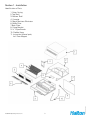
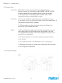
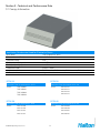
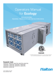
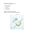
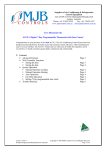
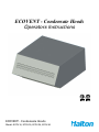
ECOVENT - Condensate Hoods
Operators Instructions
ECOVENT - Condensate Hoods
Model: ECOV-10, ECOV-20, ECOV-30, ECOV-40
Table of Contents
Section 1 – Installation Page
1.1 Identification or parts 3
1.2 Fitting to Oven 4
1.3 Fitting Door Magnet 4
1.4 Connection to Services 5
1.5 Commissioning 6
Section 2 – Operation
2.1 Safety 7
2.2 Regular Operation 7
2.3 Cleaning and Maintenance 8
Section 4 – Recommended Spare Parts 12
Section 5 – EC Declaration of Conformity 13
ECOVENT Operating Instructions
2
ECOV/112012/rev1/EN
Section 3 – Technical and Performance Data
3.1 Canopy Information 9
3.2 Wiring Diagram 10
Section 1 - Installation
Identification of Parts
ECOVENT Operating Instructions
3
ECOV/112012/rev1/EN
1. Outer Casing
2. Top Shell
3. Bottom Shell
4. Cassette
5. Mesh Moisture Eliminator
6. Baffle Filter
7. Back Plate
8. Fixing Bracket
9. ¾” Nylon Branch
10. Flexible Hose
11. Instruction Manual pack,
Incl. Door Magnet
Section 1 – Installation
1.2 Fitting to Oven
Information:
The ECOVent condensate hood has been designed to fit on
Electrolux ovens only, specifically models 269281, 267281, 267280
No direct connection to an outgoing extract system is required,
as the steam laden air filtered by means of baffle filters, mesh
moisture eliminators and perforated cassette.
Instruction: 1.2.1 Unscrew the 2 No. centre fixing screws, located to the rear
of the ovens, that fix the roof panel in place. Screw the fixing bracket (8)
into position using the holes provided.
1.2.2. Remove the nuts from the two locating studs fitted to the
bottom rear of the condensate hood.
Safety: 1.2.3. Carefully lift the condensate hood ( kg) into position, ensuring
the locating stud fit into the holes on the fixing bracket. Take care
To lift condensate hood clear of the flues exposed on the roof of the
oven. Refit nuts and tighten.
1.2.4. Check steadiness of unit when condensate hood is lifted on
combi steamer.
1.2.5. Condensate hood is not developed for floor standing units.
1.2.6. Before connecting the condensate hood ensure the information
on the rating plate corresponds.
1.3 Fitting Door Magnet
ECOVENT Operating Instructions
4
ECOV/112012/rev1/EN
Fig 1.
Section 1 – Installation
Instructions: 1.3.1. Place the door magnet (11) as Fig 1. and mark the fitting
hole on top of the oven door.
1.3.2. Drill on No. 2.4mm diameter hole, and tap with M3 thread.
1.3.3. Fix the magnet into place, ensuring the distance is set to read,
when door is opened to ventilation position.
The reed switch is already fixed to the condensate hood.
Information: Instruction: 1.4.1 Cold Water Supply. Fit the ¾” nylon Y branch (9) to the
inlet connection on the underside of the oven. Onto this flexible
hose (10) is to be fitted, with the opposite end connecting to the
inlet on the rear of the condensate hood. Check your Electrolux
manual for correct water quality etc.
1.4.2. Drain Connection. The drain pipe has been designed to
allow ease of interface with a 1 ¼” waste pipe. The smaller pipe
is an overflow, and should not be connected to the waste.
1.4.3. Electrical Supply. Remove the back plate (7) to allow access
to controls compartment. Connect a 120v/1/60 supply into the
designated connector block. Refit to panel.
For further information see wiring diagram in section 3.2
Information: ECOVENT Operating Instructions
5
ECOV/112012/rev1/EN
1.4 Connection to Services
Information: The condensate hood requires a cold water supply, a suitable
waste pipe fitted to the drain and a 120 volt single phase
electrical supply.
Section 1 – Installation
Information: 1.5.1. Sequence of Operation. If all of the services have been
connected correctly, the sequence of operation is as follows.
Green illuminated on-off toggle switch will turn condensate hood
power on. At this time the fan will run at low speech (Idle). When
the door of the oven is opened, the magnetic reed switch triggers
the fan to increase in speed, and a cold water mist to be produced.
This will run for 24 seconds (factory setting) before returning to idle.
Closing the door will also return the condensate hood to idle.
Instruction: 1.5.2. Prior to running the condensate hood for the first time, ensure
that both the mesh moisture eliminator (5) and baffle filters (6) are
fitted. Ensure all services and drains have been connected as
described in section 1.4 and oven is switched off.
1.5.3. Turn power on via toggle switch. Fan will run. Open oven
door to confirm activation of reed switch and allow to run for the
full 24 seconds. (Until the water stops automatically.) Open and
close the door twice more (and run for the full 24 seconds), to
allow the weir in the base of the condensate hood to fill. The
condensate hood is now ready for use.
ECOVENT Operating Instructions
6
ECOV/112012/rev1/EN
1.5 Commissioning
Section 2 – Operation
2.1 Safety
Safety 2.1.1. The ECOVent condensate hood is designated only for
extracting steam and vapor from Electrolux ovens only,
specifically models 269281, 267281, 267280.
2.1.2. The manufacturer accepts no liability of damages in case of
non-designated use, or incorrect operation or installation.
2.1.3. The protection class IP55 of the condensate hood does not
include the connection cable-shock-proof socket.
2.1.4. Always disconnect from the power supply, before carrying
out any cleaning operations.
2.1.5. Do not clean the condensate hood with any type of high
pressure cleaner, water sprayer or hose.
2.1.6. Regularly clean the baffle filters, inside and outside of the
condensate hood.
2.1.7. Excess grease build up on any part of a condensate hood
presents itself as a possible fire hazard. Ensure baffle filters are
cleaned regularly, and while they are removed clean internal
areas that are accessible.
2.1.8. Damage due to irregular cleaning invalidates any warrantee claim.
2.1.9. Always ensure condensate hood is running when oven steamer
is operating. This will reduce condensation within the condensate hood.
2.2 Regular Operation
2.2.2. During cooking operations, opening the oven door should be
done carefully. Open the door to the ventilation position (raised
handle), as described in the Electrolux user manual, and leave
for a few seconds (approx. 15) before opening fully. This will allow
the majority of the steam and vapors to be removed efficiently.
2.2.3. Turn off power to condensate hood during extended periods
of inactivity, such as overnight of between sessions.
ECOVENT Operating Instructions
7
ECOV/112012/rev1/EN
Instruction: 2.2.1. Day to day operation of the condensate hood requires very
little user interaction as the condensate hood is essentially automatic
Section 2 – Operation
2.3 Cleaning and Maintenance
Safety: 2.3.1. Before cleaning or carrying out maintenance on the
condensate hood, ensure the power supply is disconnected.
Information: 2.3.2. The baffle filters should be removed and cleaned in a
dishwasher regularly, at least every two weeks.
Experience could suggest more frequently, dependant on
contaminant build up.
2.3.3. The condensate hood casing should be cleaned of
contaminant build up, inside and out, with a hot mild cleaning
solution and dried with a towel.
2.3.5. The removable mesh moisture eliminators should
be cleaned with a hot cleaning solution regularly, at least every
four weeks, or as experience suggests.
2.3.6. The cold water mist nozzles should be checked for operating
and the apertures cleaned with fine wire, when required.
2.3.7. To remove baffle filters, lift and swing bottom away from
you. Pull out top first. To remove mesh moisture eliminators grab
knobs and pull towards you. To refit reverse procedures.
2.3.4. No corrosive or highly caustic alkaline cleaners or
sourcing cleaning solution should be used.
2.3.8. Once a year the condensate hood should be checked by a
technician.
2.3.9. Troubleshooting:
• Fan always runs in high speed, or
never in high speed.
• Steam and vapor is not condensed
• Check if power plug is connected and
main switch is on
• Call customer service
• Has the door magnet been fitted, and if
so, is it in the right position?
• Call customer service
• Ensure water is connected to the hood
Safety: 2.3.9 Under no circumstances must unqualified personnel
attempt any repair of servicing within the back panel section
of the condensate hood. Risk of electric shock which can cause
serious injury or death. If technical difficulties are experienced
contact your local service agent.
ECOVENT Operating Instructions
8
ECOV/112012/rev1/EN
• Fan does not run
Section 3 – Technical and Performance Data
3.1 Canopy Information
Ventilation Condensate Hood for Electrolux Ovens
Main Power
120V single phase, 60Hz
Full Load Current (F.L.C.)
4 AMP max.
Protection Rating
IP55
Fan Capacity - Low Speed
211 CFM
Fan Capacity - High Speed
444 CFM
Cold Water Supply
Always > 40PSI
Weigth
ECOV-10 --- lbs, ECOV-20 ---lbs, ECOV-30 --- lbs, ECOV-40 --- lbs
Construction Material
18 ga. stainless steel
ECOV-10
ECOV-20
Electrolux Oven air-o-convect 62 & 102
Electrolux Oven air-o-convect 62 & 102
PNC 269281
Model:
PNC 267281
PNC 266281
PNC 267321
PNC 269283
PNC 267283
PNC 266283
PNC 267323
ECOV-30
ECOV-40
Electrolux Oven air-o-convect 61 & 101
Electrolux Oven air-o-convect 61 & 101
Model:
Model:
PNC 267280
PNC 269280
PNC 267320
PNC 266280
PNC 267282
PNC 269282
PNC 267322
PNC 266282
ECOVENT Operating Instructions
9
ECOV/112012/rev1/EN
Model:
HALTON LIMITED WARRANTY
Halton (“Manufacturer”). Warrants only to its direct purchasers and to no others, that all products
manufactured by the Manufacturer shall be free from defect in materials and workmanship for a period
of twelve (12) months from the date of the original installation and start-up or eighteen (18) months
from date of shipment, whichever occurs first. All products sold but not manufactured by Manufacturer
will be warranted for a period of twelve (12) months from date of shipment.
For products manufactured by the Manufacturer we agree to pay any reasonable labor costs necessary
to repair or replace, at Manufacturers option, defective parts or materials for a period of twelve (12)
months from date of original installation and start-up or eighteen (18) months from date of shipment,
whichever occurs first. All labor costs subject hereto shall be performed during standard work hours at
straight-time rates.
For products sold but not manufactured by the Manufacturer we agree to pay any reasonable labor costs
necessary to repair or replace, at Manufacturers option, defective parts or materials for a period of (90)
days from date of original installation and start-up or (12) months from date of shipment, whichever
occurs first. All labor costs subject hereto shall be performed during standard work hours at straighttime rates.
Purchaser shall pay incurred premium labor charge, including overtime, weekends and holidays.
Travel time, service charges, miscellaneous tools, material charges, and labor charges resulting from
inaccessibility of equipment will not be paid by Manufacturer.
This LIMITED WARRANTY SHALL APPLY ONLY to products that have been installed and maintained
in accordance with the installation and Care Instruction Manuals. Purchaser shall be solely responsible
for adhering to the instructions and procedures set forth in the said instruction manuals.
This LIMITED WARRANTY SHALL NOT BE APPLICABLE to any damage or defect resulting from fire,
flood, freezing or any Act of God, abuse, misuse, accident, neglect or failure to adhere to all instructions
set forth in the installation and Care Instruction Manuals. Furthermore, this limited warranty shall not
apply to any product that has been altered, unless such alteration has been approved in writing by a
duly authorized representative of the manufacturer. In no event shall the manufacturer be liable for any
loss, expense, personal injury or consequential damage, of any kind or character, as may result from a
defect in material, and/or workmanship, however caused.
EXCEPT AS IS EXPRESSLY SET FORTH IN THIS LIMITED WARRANTY, MANUFACTURER MAKES
NO WARRANTY OF MARKETABILITY FOR FITNESS OR ANY PARTICULAR PURPOSE. NEITHER
DOES MANUFACTURER MAKE ANY WARRANTY, EXPRESSED OR IMPLIED, WITH RESPECT TO
PRODUCTS SOLD BY MANUFACTURER OR AS TO THE USE THEREOF.
Halton Company
101 Industrial Drive, Scottsville, KY 42164
Phone 270 237 5600 Fax 270 237 5700
Halton Indoor Climate Systems, Ltd.
1021 Brevik Place Mississauga, ON L4W 3R7
Phone 905 624 0301 Fax 905 624 5547
www.haltoncompany.com