1
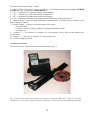
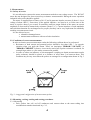
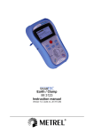
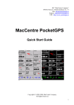
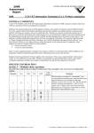
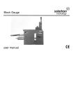
ATMOR sc
Elektronika Pomiarowa
80-809 Gdańsk, ul. Chałubińskiego 29
tel., fax (0-58) 679-56-56, 0-601-68-78-53
Gdańsk, 2008
USER MANUAL
EARTHING IMPULSE METER
TYPE WG-407
1. Description of the meter
1.1. General remarks
A meter WG-407 has been designed for earthing resistance measurements at impulse time
parameters similar to those met at real atmospheric discharges. The applied impulses achieve a value
of about 1 A at a voltage of about 1000 V. Time parameters of the measurement impulses fulfil
requirements of the following standards: PN-92/E-04060 and PN-EN 60060-2:2000. The meter
has been designed for checking of all lightning protection earthings, especially in objects submitted
to increased rigours and specially protections required by PN-89/E-05003/3 and PN-89/E-05003/4,
for example petrol or gas stations. The meter is eapecialy useful for measurements of transmission
line tower earthings. Resistance tests of line tower earthings by means of clasic low frequency meters
need disconnection of the tested earthing from the tower, so it is time consuming and the line must be
switched off. Use of impulse current makes tower earthing tests without disconnections and, what is
more, they can be done on line in service. There can be applied different definitions of impulse
resistance, as well as of operating temporary values, but only the definition using peak values of
current and voltage drop has found practical realization. Such a way corresponds to the European
Standard PN-IEC 61024-1, where a definition of an "earthing equivalent resistance" is explained as
"a ratio of maximum values of voltage drop and current, whitch usually are not at the same time".
1.2. Technical data
1. Two measuring ranges (automatic selection): 0 – 19.9 Ω and 20.0 – 199 Ω
2. Errors: basic error 2.5 %, total error 5.0 %
3. Power supply: internal battery 4.8 V Cd-Ni, 1 Ah with discharge and charge control system.
The battery is sufficient for about 1000 measurements.
4. LCD display – 2 and half significant digits
5. Dimensions: 100 x 195 x 40 mm
6. Weight: meter – 0.4 kg, with accessories – 3.7 kg
• 2 stakes (φ 10 mm, 0.6 m long)
• single conductors 1x0.75 mm2:
1) current probe – 40 m,
2) voltage probe – 30 m
3) tested earthing – 2 m
• net power supply
1.3. Description of the meter
1
2
3
4
5
6
8
7
10
9
Fig. 1. Meter WG-407 - a general view
2
The meter can bee seen in Fig. 1, where:
1 - switch "Zasil" - the meter is turn on and off, on a LCD display appears an inscription: ATMOR
WG407 and a few seconds later "Menu measure"
2 - “Zx” – a socked to be connected with the tested earthing
3 - “Su” – a socked to be connected with the voltage probe
4 - “Si” – a socked to be connected with the current probe
5 - LCD – a liquid crystal display, the display may be light up by pushing a button "+"
6 - a button "Start" - when you push that button a measurement or another process chosen by the
button "Menu" is started,
7 - a button "Menu" - a choice of operation mode of the meter:
a) measurement
b) memory service: writing, reading or erasing measurement results
c) battery test
8 - a button "+" - an increase of a number of a read memory cell or light up the display after
measurement
9 - a button "-" - a decrease of a number of a read memory cell
10 - a battery charging socked
1.4. Meter accessories
The WG-407 meter with its accessorie has been shown in Fig. 2
Rys. 2. General view of the meter and its accessories: 1- the meter WG-407, 2 –bag, 3 – reel with
conductors, 4 – net power supply for battery charging, 5 –protective coverof measurement probes
3
2. Measurements
2.1. Safety of service
It is not allowed to connect the meter measurement sockeds to any voltage source. The WG 407
meter has not designed for short circuit loop resistance measurements! During the meter operation
industrial safety rules should be applied.
The meter is supplied from a battery of 4.8 V and it generates impulse currents of about 1 A at a
voltage of about 1000 V. Front times of the applied impulses are equal to 4 µs. Pulse rate of the
meter is equal to about 5 per second. If somebody touch an output socked of the meter an current
amplitude is decreased by human body resistance (about 3 kΩ). Current impulses of such amplitude
and such short duration are not dangerous for peoples, but they can be very unpleasent for somebody
touching a measurement circuit.
It is not allowed to use:
• a humid or damaged meter
• measurement conductors with out of order insulation
2.2. Conditions of correct measurements
In order to obtain correct measurement results the following coditions has to be performed:
• Resistance of both current and potential probes should be less than 1000 Ω. In opposite
situation when you push the button "Start" an inscription "ERROR! VOLTAGE" or
"ERROR! CURRENT"is shown. A test can be carried out if probe resistance is reduced, for
example biger stakes or a few stakes connected in parallel.
• In order to reduce an influence of electromagnetic coupling on obtain measurement results
probe coductors should be placed at a distance of more than 5 m between them. This
condition may be easy meet when the probes are arranged in a configuration shown in Fig. 3
Fig. 3. A suggested configuration of measurement probes
2.3 Measuring, writing, reading and erasing procedures
2.3.1 Measuring
• Drive probes into soil, reel off conductors and connect them to the meter taking into
consideration remarks mentioned in p. 2.2,
4
•
•
Power on the meter using swich “Zasil”, wait until the display shows the inscription
"ATMOR WG 407" and a few seconds later the inscription “Menu measure”, the meter is
ready to measurement,
Push the button “Start”, the meter perform a mesurement circuit test (the inscription "testing
circuit") and the display shows a result of a tested earthing - an inscription: "me? Menu
...Ω
Ω". In this state yuo can light up the display pushing the button "+". Every following
pushing the button “Start” starts a mesurement procedure. If you see the inscriptiont
"ERROR! VOLTAGE" or "ERROR! CURRENT" instead of an measurement result,
measurement circuit resistance seems to be to high - see p. 2.2.
2.3.2 Writing, reading and erasing procedure in memory
• In order to write a measurement result shown on display you should push the button “Menu”
, the inscription “write Me ... Ω” appears and when you push the buttonu “Start”, a result
from the display is writen in the meter memory and an inscription "OK ... Me ...Ω
Ω” appears
on the display. A number in the first part of the inscription shows a position of the writing in
the meter memory. A result is writen at the lowest free position. When you push the button
“Start” at the inscription "OK ... Me ...Ω
Ω”, a measurement procedure is started again
without change of operation mode by usage of the button “Menu”.
• In order to read writen in the memory results you should push the button “Menu” until an
inscription “Menu read” appears and then push the button “Start”. An inscription “#
## ... Me
...Ω
Ω” on the display appears, where the first number denotes a position of a result shown on a
second position. You can change the read position by pushing the buttons "+" or "-".
• A storage capacity is able to read 126 results. In order to erase and clear the meter memory
you should find an inscription “write Me” or “write Me ...Ω
Ω”, next push and keep the button
“+”, then push and keep the button “-“, afterwards you should release the pushed button “+”,
and the button “-“ must be kept until you see an inscrition “clear Me”, afterwards release the
pushed button “-“. If you push the button “Start” at the inscrition “clear Me” all results
writen in the meter memory are erased.
3. Supply system of the meter
3.1 Battery test
The meter WG-307 is powered by a 4.8 V Cd-Ni battery. A battery set of capacity 700 - 1000
mAh as usualy the meter is equipped seems to be sufficient to perform about 1500 measurements. A
battery container there is under a cover on a rear panet of the meter. You can remove the cover
pushing the cover in a direction shown by an arrow with inscripion „OPEN”.
In order to check a battery charging ratio you should push the button „Menu” until an inscription
„Bat. Menu Test” appears and then push the button „Start”. The meter starts to test the battery (an
inscription „Test bat. >>>”) and finaly an inscription „Test bat. ...%” appears. The number denotes
a level of battery charge.
When a battery voltage becomes to low, the meter resets and on its display appears an
inscriptiona "ATMOR WG 407".
3.2 Battery charging
The meter is equipped with inner charging system and the battery can be charged without taking
out the battery from a container. In order to start with battery charging procedure you should swich
off the meter and a net power supply pin must be plug to the meter socked. The meter starts with a
charging procedure automaticaly.
At the begining the charging level of the battery is checked and on the display appears an
inscription „Charger test bat”. If the battery level is higher than 30% of rated one, an inscription
5
„Charger Ful” and the battery is not charged. In opposite situation a two stages charging process
starts. First stage refers to battery discharging - an inscrition „ Charger discharg”. In the second
stage appears an inscription „Charger charging” and the meter starts to charge battery. When you
noticed an inscription „ Charger Full” it denotes that the charging process has been finished.
4. Maintenance
• Electrical circuit of the meter does not require maintenance. Accuracy check of the meter
should be done accordingly to Producer’s Standard WT-06-01/407.
• The meter is powered with NiCd accu pack of 4.8V. In emergency 4 AA alkali batteries can
be used.
• Battery compartment is on the back of the meter.
• The confirmation of the accuracy is made in Okregowy Urząd Miar in Gdańsk (PL).
5. Warranty
The producer gives 1-year warranty. The warranty card is on the last page of the manual user.
ATMOR sc Elektronika Pomiarowa
ul. Chałubińskiego 29
80-809 Gdańsk
office adress.: ul. Kujawska 4/9, 84-232 Rumia
tel., fax (0-58) 679-56-56, 0-601-68-78-53
Warranty of
EARTHING IMPULSE METER
Type WG-407, Nr _____________________
Gdańsk, date________________________________________
1.
2.
•
•
•
•
3.
Date
The producer gives 1-year warranty
Warranty does not cover the results of improper exploitation
mechanic fatigue
pouring liquids
improper battery
wrong battery polarisation
The battery is not the subject of warranty
signature of seller
6