1
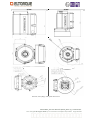
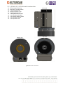
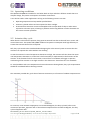
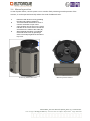
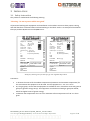
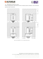
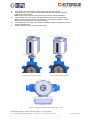
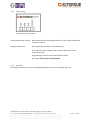
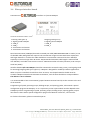
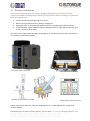
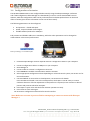
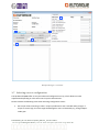
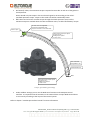
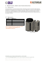
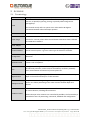
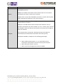
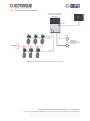
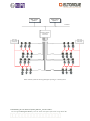
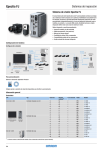
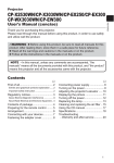
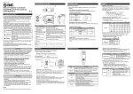
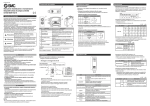
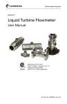
Document ID: EX150.0001_02 USER MANUAL Electrical Part-turn Valve Actuators QT 250 2.2/ 2.3 EX Revision Date: 18.08.2014 QT 800 2.2/2.3 EX EX150.0001_03 User Manual QT250_800 2.2_2.3 EX CanBus Last changed 18 August 2014 by Tove M. Moe and Bjørn Nybrodahl Page 2 of 29 Table of Contents 1 INTRODUCTION............................................................................................................................................. 4 1.1 1.2 1.3 1.4 1.5 2 SPECIFICATIONS AND MANUAL OPERATION ................................................................................................. 5 2.1 2.2 2.3 2.4 2.5 2.6 3 MAINTENANCE ............................................................................................................................................... 21 SPARE PARTS.................................................................................................................................................. 21 TROUBLESHOOTING......................................................................................................................................... 22 APPENDIX ................................................................................................................................................... 24 5.1 5.2 6 SAFETY INSTRUCTION ....................................................................................................................................... 11 MOUNTING ACTUATOR ON VALVE ...................................................................................................................... 12 ELECTRICAL CONNECTIONS ................................................................................................................................ 14 ELTORQUE INTERFACE BOARD ............................................................................................................................ 16 ELECTRICAL INSTALLATION ................................................................................................................................ 17 CONFIGURATION OF ACTUATOR ......................................................................................................................... 18 SELECTING CORRECT CONFIGURATION ................................................................................................................. 19 MAINTENANCE, SERVICE AND TROUBLESHOOTING .................................................................................... 21 4.1 4.2 4.3 5 TECHNICAL DATA .............................................................................................................................................. 5 QT250 2.2/2.3 EX EXTERNAL CONSTRUCTION...................................................................................................... 7 QT800 2.2/2.3 EX EXTERNAL CONSTRUCTION...................................................................................................... 8 OPERATING CONDITIONS .................................................................................................................................... 9 ACTUATOR DUTY CYCLE ...................................................................................................................................... 9 MANUAL OPERATION ...................................................................................................................................... 10 INSTALLATION............................................................................................................................................. 11 3.1 3.2 3.3 3.4 3.5 3.6 3.7 4 VALVE INTERFACE ............................................................................................................................................. 4 MAX OPERATION TORQUE .................................................................................................................................. 4 CLOSING TIME .................................................................................................................................................. 4 REMOTE CONTROL ............................................................................................................................................ 4 EMC LOCATION CLASS ACCORDING TO DNV ......................................................................................................... 5 TERMINOLOGY ............................................................................................................................................... 24 CONTROL SYSTEM EXAMPLES............................................................................................................................. 26 DOCUMENT HISTORY .................................................................................................................................. 28 EX150.0001_03 User Manual QT250_800 2.2_2.3 EX CanBus Last changed 18 August 2014 by Tove M. Moe and Bjørn Nybrodahl Page 3 of 29 1 INTRODUCTION Eltorque is a model range of electric valve actuators suitable for use in a wide variety of industrial environments. The Eltorque actuators are characterized by: Compact size and good torque to size/weight ratio. Flexible control interfaces for easy integration with a wide range of control systems. Low power consumption. Electronic configuration of speed, torque and other parameters. Easy and cost effective installation. Maintenance free. The QT250 product is suitable for use on part-turn valves with an operating torque below 250 Nm, while the QT800 is suitable for 250-800 Nm. Most part-turn valves utilize quarter-turn (90) movement, but the QT250 and QT800 can easily be configured to an operation area within the range 0-359. During the purchasing process, it is important to consider the following parameters. 1.1 Valve interface It must be checked that the spindle and valve mounting holes either fit directly onto the actuator or alternatively consider spindle adapters and valve brackets. 1.2 Max operation torque The actuator must have sufficient torque to operate the valve in all applicable conditions. 1.3 Closing time This is usually determined as a part of the process development. In some cases, the closing time should be as short as possible if the valve for example is shutting down a system in case of failure. In other cases, a longer closing time is desired, to avoid shock waves in pipe systems with high pressure or flow. The QT250 and QT800 have electronically configurable closing times. 1.4 Remote Control The QT250 & 800 can be controlled remotely by CANopen (fieldbus, max 127 actuators per network). For more details about the functionality of this control interface, see chapter “3.4 Eltorque interface boards”. EX150.0001_03 User Manual QT250_800 2.2_2.3 EX CanBus Last changed 18 August 2014 by Tove M. Moe and Bjørn Nybrodahl Page 4 of 29 Additionally, the actuator can be configured and controlled from a computer using a dedicated cable and a software tool called Eltorque Manager 4. 1.5 EMC Location Class according to DNV For EMC Location Class B there must, in addition to the actuator, be installed a PSF unit as a filter to obtain compliance to the Class requirements. This filter can be used with both versions 2.2 and 2.3 of the QT 250/800 Ex. For EMC location class A the version QT250/800 2.3 Ex must be chosen. 2 SPECIFICATIONS AND MANUAL OPERATION 2.1 Technical data Torque Closing time Dimensions (HxWxD) Weight Valve flanges (Ref. ISO5211) Standard valve adapter Valve applications Operation temperature Color Encapsulation Control interface Position sensor Power supply Power consumption Over/ under temperature protection Manual operation QT250 2.2/2.3 EX 50-250 Nm 0-90 movement: 13 -60 sec 229 x 156 x 209 mm 12 kg QT800 2.2/2.3 EX 160-800 Nm 0-90 movement: 42 -180 sec 333 x 200 x 239 mm 21 kg F05, F07 & F10 F10 & F12 SQ17 SQ27 Butterfly or ball valves with part-turn operation Butterfly valve examples: DN50-DN200 PN16 DN250-DN350 PN16 -25 – 70 C -25 – 70 C Silver Silver IP68 (10m 72hrs) (IEC605229) IP65 (IEC 60079-0) Corrosion protected aluminium and steel enclosure CANopen (Fieldbus) Range: 360° - 0,4° resolution Position feedback not corrupted by power failure 110 - 240 V AC ± 10%, 50/60 Hz, Max 130 W At 250/800 Nm load: <130 W Standby: <15W Motor current is switched off in case of over-temperature Manual override without tools, max 4 Nm torque 21 turns on hand wheel = 74 turns on hand wheel = 90 movement on valve 90 movement on valve EX150.0001_03 User Manual QT250_800 2.2_2.3 EX CanBus Last changed 18 August 2014 by Tove M. Moe and Bjørn Nybrodahl Page 5 of 29 QT250 QT800 External, valve flange and spindle dimensions EX150.0001_03 User Manual QT250_800 2.2_2.3 EX CanBus Last changed 18 August 2014 by Tove M. Moe and Bjørn Nybrodahl Page 6 of 29 2.2 QT250 2.2/2.3 EX External construction 1. 2. 3. 4. 5. 6. 7. 8. 9. Motor and gear housing Bracket for control interface Control Interface Box Manuel operation cover Cable gland holes 5 x M20 Valve spindle shaft SQ17 Valve flange fastening holes Valve position indicator Valve position scale Front view 4 3 2 1 Top view Bottom view 8 7 6 9 5 QT250 External construction EX150.0001_03 User Manual QT250_800 2.2_2.3 EX CanBus Last changed 18 August 2014 by Tove M. Moe and Bjørn Nybrodahl Page 7 of 29 2.3 QT800 2.2/2.3 EX External construction 10. 11. 12. 13. 14. 15. 16. 17. 18. 19. Motor and gear housing Bracket for control interface Control Interface Box Manuel operation cover External gear housing Cable gland holes 5 x M20 Valve spindle shaft SQ27 Valve flange fastening holes Valve position indicator Valve position scale Front view 4 3 2 1 5 Top view Bottom view 8 7 9 10 6 QT800 External construction EX150.0001_03 User Manual QT250_800 2.2_2.3 EX CanBus Last changed 18 August 2014 by Tove M. Moe and Bjørn Nybrodahl Page 8 of 29 2.4 Operating conditions The QT250 and QT800 are suitable for use below deck on ships and other offshore vessels due to its compact design, low power consumption and robust construction. It can also be used in other applications as long as the following criteria’s are met: Operating temperature is kept within specified limits. Actuator is placed indoors and not exposed to direct sunlight. Protected from extensive corrosive atmospheres like on open deck of ships or other areas exposed to salt water spray. Cleaning or pollution with strong alkaline or acidic chemicals can also cause corrosion problems. 2.5 Actuator duty cycle When electric valve actuators operate, they generate internal heat due to thermal loss in motor and – control electronics. The QT250 and QT800 combines low power consumption with high efficiency to ensure that internal thermal loss is kept low. Still, duty cycle needs to be considered when designing the valve control system to ensure that the actuators can operate the valves without over-heating. In case the actuator’s internal temperature becomes too high, the actuator will shut down the motor until temperature decreases to a safe level. This functionality is implemented in the firmware of the actuator. If the firmware fails for some reason, internal fuses in hardware will trigger to prevent overheating of the actuator or too high currents in the electronics. These fuses are not resettable. To avoid problems with over-temperature alarms and actuator shutting down, duty cycle requirements should be considered before selecting actuator. The maximum possible duty cycle due to firmware restrictions, as a function of ambient temperature is: For instance, if the ambient temperature has reached 65 degrees, the duty cycle will, after some continuous operation, approach 34%. If the ambient temperature has reached 70 degrees, the duty cycle will approach 20%. EX150.0001_03 User Manual QT250_800 2.2_2.3 EX CanBus Last changed 18 August 2014 by Tove M. Moe and Bjørn Nybrodahl Page 9 of 29 2.6 Manual operation In case of power failure, control system error or another fault preventing normal operation of the actuator, it can be operated manually without the need of additional tools: 1 2 3 4 Remove hand-wheel cover by grabbing the tabs and pulling it straight up. Turn hand-wheel Clockwise to close or Counter-clockwise to open valve. Valve position can be seen on the visual indicator in the centre of the hand-wheel and reference is made to the scale (D). When Manual Operation is completed, refit hand wheel cover by pressing it down until it stops against the actuator’s top cover. 1 3 2 Removing hand-wheel cover 2 Manual operation features EX150.0001_03 User Manual QT250_800 2.2_2.3 EX CanBus Last changed 18 August 2014 by Tove M. Moe and Bjørn Nybrodahl Page 10 of 29 3 INSTALLATION 3.1 Safety instruction The product is marked with the following warning: “Warning – Do not separate while energized” Ta -25 ~ +700C Input 110-240 V AC Frequency 50-60 Hz Power, peak 130 W Power, avg 10-20 W Interface input 0 - 5,25 V DC IP 65 (IEC60079-0) IP 68 (10m/72h) (IEC60259) P/N S/N Prod.date dd.mm.yyyy Motor ID Eltorque AS N-7125 Vanvikan Ex e ib mb IIC T4 Gb IECEx NEM 13.0042 Norway Web: www.eltorque.com System SFI Number Loop Bus address QTXXX 2.2 EX CanOpen Torque max XXX Nm Ta -25 ~ +700C Input 110-240 V AC Frequency 50-60 Hz Power, peak 130 W Power, avg 10-20 W Interface input 0 - 5,25 V DC IP 65 (IEC60079-0) IP 68 (10m/72h) (IEC60259) P/N S/N Prod.date dd.mm.yyyy Motor ID Eltorque AS N-7125 Vanvikan Ex e ib mb IIC T4 Gb IECEx NEM 13.0042 Norway Web: www.eltorque.com System SFI Number Loop Bus address WARNING - DO NOT OPEN WHILE ENERGIZED QTXXX 2.3 EX CanOpen Torque max XXX Nm WARNING - DO NOT OPEN WHILE ENERGIZED All personnel working with equipment and installation in a hazardous area must have proper training, and shall therefore understand the EX-related marking on the label. Under is an example of the label for Eltorque products QT250 2.2 Ex and QT800 2.2 Ex. Example of marking label for Eltorque QT 250 & QT800 EX products Comments: Ta denotes the interval of the ambient temperature (maximum and minimum temperature) for the environment the equipment can be used. For this equipment Ta= -25 °C to +70 °C. IIC, the gas group, means that the equipment is certified for use in hazardous areas with gases in group IIC (ignition energy>20 µJ). The equipment can also be used with gas group IIA and IIB, which has higher limits of ignition energy. T4 denotes the temperature class. T4 has a maximum surface temperature of 135 °C in the Ta given. EX150.0001_03 User Manual QT250_800 2.2_2.3 EX CanBus Last changed 18 August 2014 by Tove M. Moe and Bjørn Nybrodahl Page 11 of 29 3.2 Mounting actuator on valve Before mounting actuator, please make sure there is sufficient space for installation, service and manual operation above and around it: Space for installation, service and manual operation EX150.0001_03 User Manual QT250_800 2.2_2.3 EX CanBus Last changed 18 August 2014 by Tove M. Moe and Bjørn Nybrodahl Page 12 of 29 1. 2. 3. 4. 5. Apply grease on valve spindle to ease mounting and avoid corrosion. Lift actuator onto valve; align its valve adapter with the valve spindle and lower actuator onto valve flange. Note: Keep hands away from the valve flanges to avoid crushing damages. Use hand wheel to turn actuator and align fastening holes of the valve flanges. Note: In order to achieve optimal functionality of valve position indicator, actuator should be positioned as shown in Figure 3 below. Insert fastening screws and use washers according to ISO5211 standard and valve vendor’s specifications. Tighten fastening screws to the specified torque. 1 Lowering actuator onto valve Correct orientation of actuator Figure 3: Aligning fastening holes and inserting screws EX150.0001_03 User Manual QT250_800 2.2_2.3 EX CanBus Last changed 18 August 2014 by Tove M. Moe and Bjørn Nybrodahl Page 13 of 29 3.3 Electrical connections Eltorque Ex actuator is delivered with transport plugs covering the connection holes in the electronic and interface box. These transportation plugs must be removed and replaced with EX approved glands according to the appropriate Ex protection class. 3.3.1 Power supply: 230V AC 50/60 HZ Cable glands: Use suitable and approved EX cable glands. Follow instructions given by manufacturer. When choosing cable glands, account for a temperature rise ΔT = 20 ˚C under normal operation. For actuators that will be used in an ambient temperature of 70 ˚C, the cable glands must be specified for operational temperature of at least 70 + 20 = 90 ˚C Cable: 2x1.5mm2 + GND (max 2.5mm2). It is possible to connect more than one actuator to the same circuit. Recommended fuse size is 2x10A, 13A, 16A. At maximum torque, 250Nm, maximum power consumption is 130W. At max holding torque, 175 Nm, maximum power consumption is 70W. Motor starting current is approx. 5 times normal operating condition after loss of power supply (use time-lag fuses, C-characteristics). IMPORTANT: DO NOT SEPARATE WHEN ENERGIZED! 3.3.2 Control facilities Cable glands: Use suitable and approved EX cable glands. Follow instructions given by manufacturer. Cable: Recommended core dimension is 0.75mm2 (maximum 1.5mm2) UNITRONIC BUS CAN or similar. Number of conductors: See section 0 Eltorque interface board. General: Push buttons, PLC or similar types of process-control systems can be used for controlling Outputs and inputs: TM QT250. See section 0 Eltorque interface board. 3.3.3 EX Certification number: IECEx NEM 13.0042 Ex e ib mb IIC T4 Gb Area classification: Zone 1 – Areas where and explosive atmosphere occurs occasionally under normal operation conditions. Max surface temperature is 135°C. Installation and preparation must be done according to requirement in Ex-directive, also compliance with directive EN-60079-14. EX150.0001_03 User Manual QT250_800 2.2_2.3 EX CanBus Last changed 18 August 2014 by Tove M. Moe and Bjørn Nybrodahl Page 14 of 29 3.3.4 Programming Terminal connection RS232 (X2) Pre-programming by supplier: Other values than the pre-programmed ones, can be ordered when the actuator is ordered. Programming by user: Re-programming can also be performed by user. This is done by special software and a special cable, which can be ordered separately. Programming can also be performed by bus interface. See section 3.4 Eltorque interface boards. 3.3.5 Assembly EX CANopen interface can only be assembled with QT250 2.2/2.3 EX or QT800 2.2/2.3 EX. EX150.0001_03 User Manual QT250_800 2.2_2.3 EX CanBus Last changed 18 August 2014 by Tove M. Moe and Bjørn Nybrodahl Page 15 of 29 3.4 Eltorque interface board TM Connections of Interface: 2.2/2.3 EX CANopen Terminal connections: Max 1.5 mm2 Incoming cable (port 1) 1: Signal ground CANopen 2: CAN_H 3: CAN_L 4: Termination end resistor 5: Termination end resistor Outgoing cable (port 2) 6: Signal ground CANopen 7: CAN_H 8: CAN_L Serial communication (CANopen) demands a twisted pair cable (UNITRONIC BUS CAN or similar). In use of shielded cable, EMC glands are required. The transmission range increases with lower capacitance and larger diameter in a cable. The cable should have a transmission resistance less than 70m/m especially on bus line longer than 40 meters. Recommended maximum cable length is 250m at baud rate 125 kbit/s and cable cross section 0.75 mm². Maximum number of nodes (actuators) is 50 units per serial line (LOOP). Interface board 2.2/2.3 EX CANopen should be connected to terminals CAN_H, CAN_L and signal ground for incoming/outgoing cable (port 1/port 2). CANopen is designed for multidrop network applications. When a system is installed it should form a bus structure, star shaped networks should never be created. CANopen network with maximum 50 actuators, each of them should have a unique address. The address is set in software. It is recommended to have a termination (jumper between terminal 4 and 5) on the actuator at the end of the network. Programming of speed, operating torque, holding torque, and opening grades, is done with a special configuration program via CANopen, or via a supervisory screen system which must be adapted to the CANopen protocol. Programming of speed, operating torque, holding torque, opening grades, torque limit switch is done with a special configuration program via RS232 on terminal 1, 2 and 3 on X2. For further information, please contact Eltorque AS. EX150.0001_03 User Manual QT250_800 2.2_2.3 EX CanBus Last changed 18 August 2014 by Tove M. Moe and Bjørn Nybrodahl Page 16 of 29 3.5 Electrical installation Note: Electrical installation can only be designed and made by personnel with the appropriate skills and competence. Ensure all such work is done according to applicable laws and regulations. 1. 2. 3. 4. Loosen control interface fastening crews, 6 pcs. Remove control interface box by pulling it straight out. Make sure fuses are disconnected before connection of powersupply cables is started. Install the power supply cables through the cable glands on the right side and connect them to the L, N and G/ PE terminals. Install the control signal cables through the cable glands on the left and connect them according to X1 according to specification below. 1 X1 1 2 3 4 5 6 7 8 L N G L N G 4 Removing control interface box 3 Connection terminals location CANopen Control Interface Operation of spring loaded terminals 3 4 5 CAN_L Bridge for terminal resistor 2 GND CAN_L 1 Outgoing CAN_H GND CAN_H Incoming 6 7 8 Control signal connection terminal Control Interface functionality, cable recommendations etc. are described in the “3.4 Eltorque interface boards”. EX150.0001_03 User Manual QT250_800 2.2_2.3 EX CanBus- Last changed 18 August 2014 by Tove M. Moe and Bjørn NybrodahlTurid Halsli Hagen Page 17 of 29 3.6 Configuration of actuator The QT250 and 800 actuators are configured electronically using the Eltorque Manager 4 software and a USB configuration cable. Manager 4 is distributed by e-mail or can be downloaded from our website, while the configuration cable can be purchased from local Eltorque distributor or the head office in Norway (see contact information at the start of the manual). The following parameters can be configured: End positions – Closed and Open. Speed, Torque and Near Closed region. Fieldbus address/node ID for CANopen. End positions and fieldbus address are mandatory, while the other parameters can be changed to achieve better valve control performance. X1 1 2 3 4 5 6 7 8 L N G L N G Eltorque Manager 4 installation files Connection of configuration cable 1. Install Eltorque Manager 4 and if required driver for configuration cable on your computer. 2. 3. 4. 5. 6. 7. 8. 9. 10. Connect configuration cable to a USB port on your computer. Start Manager 4 Connect cable to actuator’s configuration connector. Press Connect to establish communication with the actuator. Select appropriate configuration values depending on valve and control system, see section 3.7 for more information. Use Hand-Wheel to move valve to closed position, see section 2.6 for details. Press Set C&O and Closed is set to the actual position, while Open is set 90 away in counter clockwise direction. If further adjustment of end positions is required, move actuator to desired position and press Set Closed or Set Open. Press Open to open valve and check that actuator operates correctly. Press Close to close valve again. Disconnect configuration cable and refit control interface. Note: Make sure actuator is powered before attempting to connect actuator with Eltorque Manager 4 EX150.0001_03 User Manual QT250_800 2.2_2.3 EX CanBus Last changed 18 August 2014 by Tove M. Moe and Bjørn Nybrodahl Page 18 of 29 6 9 8 7 5 Eltorque Manager 4 screenshot 3.7 Selecting correct configuration The QT250 and QT800 offer an easy but advanced configuration set-up, which allows accurate adjustments depending on valve and control system characteristics. Please consider the following items when selecting configuration values: Set torque values according to valve’s torque specifications with a suitable safety margin. If torque is set too high, the valve might be damaged in case it is blocked by e.g. foreign objects inside pipe. EX150.0001_03 User Manual QT250_800 2.2_2.3 EX CanBusLast changed 18 August 2014 by Tove M. Moe and Bjørn Nybrodahl Page 19 of 29 On butterfly valves, the maximum torque is required to move disc in and out of the gasket in closed position. Hence should only the torque in the near closed region be set according to the valve’s specified operation torque. Torque in the travel area will be considerably lower. Ball valves tend to have a constant torque through the whole operation area, but the maximum torque is reached when the valve movement starts, so called “breakaway” torque. 96-100%, area not configurable. Fixed accel-/ decelaration ramp. Torque is the same as in the travel area. Status = Open Open Speed and running torque options: 20-100% of max Holding torque options: 0-100% of max 100 % C N lo or si m ng al re gi pe O on ni ng Near closed area Configurable 0-15% Status Closed 0-2% Near Closed 0% Speed and running torque options: 20-100% of max Holding torque options: 0-100% of max Torque, speed and region settings Under Fieldbus settings you can set the Node ID of actuators with CANopen Control Interface. It is important that all actuators in the network have a unique Node ID and that it is set correctly according to the layout of the control system. Refer to chapter “3.4 Eltorque interface boards” for more information. EX150.0001_03 User Manual QT250_800 2.2_2.3 EX CanBus Last changed 18 August 2014 by Tove M. Moe and Bjørn Nybrodahl Page 20 of 29 4 MAINTENANCE, SERVICE AND TROUBLESHOOTING 4.1 Maintenance The QT250 & 800 is in principle maintenance free; all bearings and gears are lifetime lubricated and components are designed to last throughout the actuator’s lifetime. It is however recommended that the actuator is inspected regularly to reveal any damages caused by mechanical impact, corrosion etc. Top cover gasket and manual operation shaft seal should be lubricated with suitable lubricants if they appear to be dry. 4.2 Spare parts 1. Control Interface: Part No. Description EX250.025.3 QT250 2.3 EX CANopen Interface EX800.025.3 QT800 2.3 EX CANopen Interface 2. Actuator: Part No. Description EX250.002.2 QT250 2.2 EX Actuator EX800.002.2 QT800 2.2 EX Actuator 2 Note: If control interface is replaced, it must be re-configured using Manager 4 as described in section 3.6. 1 Control interface EX150.0001_03 User Manual QT250_800 2.2_2.3 EX CanBusLast changed 18 August 2014 by Tove M. Moe and Bjørn Nybrodahl Page 21 of 29 4.3 Troubleshooting Problem description Cause & solution No response from actuator either on the control system or if you connect with Manager 4. No power supply, check fuses and wiring. No change in resistance on the hand wheel if you cycle the power supply. Actuator’s alarm output is active, on a fieldbus system it gives torque alarm. The actuator attempts to move valve when a control signal is given. Supply voltage can be checked using a voltage meter. L-N voltage should be 230 V AC ± 20%. Valve operation torque is too high, please check torque by manual operation. Be aware that foreign objects in the pipe can block the valve and that valve torque changes over time. OR Actuator torque has been set too low, increase it by using Eltorque Manager 4 as described in section 3.6. On fieldbus control systems, torque can be adjusted via the fieldbus communication. Actuator is able to operate the valve but the operation time is longer or shorter than desired. Actuator’s alarm output is active, on a fieldbus system it gives temperature alarm. The actuator responds normally to control signals. Actuator’s alarm output is active, on a fieldbus system it gives temperature alarm. The actuator does not respond to control signals. Indicator LED is “normal”. Change actuator’s speed by using Eltorque Manager 4 as described in section 3.6. On fieldbus control systems, speed can be adjusted via the fieldbus communication. Actuator’s internal temperature is 10C or less from the motor current shut-down limit. If possible, allow actuator to cool down by leaving it in standby mode for 15 minutes or more. Actuator has over-heated and the motor current is shut down to prevent damage. Make sure surrounding temperature is within limits and that the duty type requirements are followed. See section 2 for more details. Faulty control system, please ask system vendor for support. The actuator does not respond to control signals. OR On a fieldbus system, the actuator is not available. Problem with control signal wiring, please contact local Eltorque agent for support. EX150.0001_03 User Manual QT250_800 2.2_2.3 EX CanBus Last changed 18 August 2014 by Tove M. Moe and Bjørn Nybrodahl Page 22 of 29 Problem description Actuator with fieldbus interface does not respond to control signals. Cause & solution Incorrect fieldbus settings, please check configuration with Manager 4. OR The actuator responds normally when tested with Manager 4. Actuator with digital or analog interface does not respond normally to control signals. Fieldbus control system is not wired or configured correctly. Incorrect digital or analog inversion settings, please check configuration with Manager 4. OR The actuator responds normally when tested with Manager 4. Actuator does not respond neither to control signals nor when tested with Manager 4. Digital or analog control system is not wired or configured correctly. Defective control interface, must be replaced. Actuator power supply is verified with voltage meter. After replacement of interface, actuator does not operate correctly. Interface has not been configured correctly, please refer to section 3.6. Contact local Eltorque agent for support if required. EX150.0001_03 User Manual QT250_800 2.2_2.3 EX CanBusLast changed 18 August 2014 by Tove M. Moe and Bjørn Nybrodahl Page 23 of 29 5 APPENDIX 5.1 Terminology Term Description A valve is a device that regulates the flow of materials (gases, fluidized solids, slurries, or liquids) by opening, closing, or partially obstructing various passageways. Valve This manual mostly refers to quarter-turn valves with a 90 degrees movement between Closed and Open position. Valve actuator Valve flange An electric device for operation of valves in various process control systems. The surface of the valve which the actuator is fastened to. Most commonly it is holes for 4 screws, where hole size and distance between them is defined in EN ISO 5211 standard. Valve adapter A device used to connect the actuator to the valve spindle/ stem. Control Interface Electronic device controlling the valve actuator according to signals from an overall control system. e.g. PLC or other type of electronic controller. Configuration The set-up of parameters, which affects the actuator’s performance and behaviour. Hazardous area Area in which the permanent or periodical presence of explosive substances causes a risk of explosion. PLC Digital Control Analogue Control A Programmable Logic Controller is a digital computer used for automation of industrial processes, such as control of machinery on factory assembly lines, measurement and control of process plants etc. Simple control utilizing relays, on/ off switches and indicators. Allows only Open or Closed functionality for a valve actuator. Step-less control utilizing analogue current or voltage signals, e.g. 4-20 mA, 0-10 V etc. Allows positioning of the valve actuator between Open and Closed. A fieldbus is an industrial computer network for real-time distributed control of various devices, including valve actuators. Fieldbus Control When Eltorque valve actuators are controlled by Fieldbus, the functionality is extended in terms of positioning, commands, feedback and configuration. EX150.0001_03 User Manual QT250_800 2.2_2.3 EX CanBus Last changed 18 August 2014 by Tove M. Moe and Bjørn Nybrodahl Page 24 of 29 Term Description The Eltorque Modbus interface is using RS-485 serial communication utilizing the Modbus protocol. Modbus Modbus is a fieldbus which allows communication with max 31 actuators connected to the same “master-slave” network. “Master-slave” means that the Modbus controller is a master which actively sends commands and requests to the “slave actuators”. The Eltorque CANopen interface is using the CAN (Controller Area Network) communications standard. CANopen is a fieldbus which allows communication between max 127 actuators connected to the same network. It is not a “master-slave” network (ref. Modbus), hence all nodes in the network can actively send messages at their own initiative. CANopen The communication is prioritized, meaning that urgent messages are transmitted and received before information with lower priority. Compared to Modbus, CANopen has the following advantages: More reliable communication, i.e. it is more likely that the information transmitted is received correctly by the recipient. More nodes per network, max 127. More control and configuration features available. EX150.0001_03 User Manual QT250_800 2.2_2.3 EX CanBusLast changed 18 August 2014 by Tove M. Moe and Bjørn Nybrodahl Page 25 of 29 5.2 Control system examples Operator Station 17" touch monitor + compact PC Mounted in PLC cabinet door Master panel ETHERNET LOOP 1 Digital IO PUMP 1 CAN OPEN PUMP 2 Pump control Start / stop command Started / stopped feedback Failure feedback Power supply 230VAC 50/60Hz CAN OPEN Stand-alone valve and pump control with operator stations. EX150.0001_03 User Manual QT250_800 2.2_2.3 EX CanBus Last changed 18 August 2014 by Tove M. Moe and Bjørn Nybrodahl Page 26 of 29 Main control system 1 Main control system 2 ETHERNET Ethernet to CANopen Converter for Valve Control Power supply 230VAC 50/60Hz (serial power) Power supply 230VAC 50/60Hz (serial power) CANopen Loop 1A Loop 1B Loop 2A Loop 2B Loop 3A Loop 3B Loop 4A Loop 4B Valve control system as an integrated part of a larger control system. EX150.0001_03 User Manual QT250_800 2.2_2.3 EX CanBusLast changed 18 August 2014 by Tove M. Moe and Bjørn Nybrodahl Page 27 of 29 6 DOCUMENT HISTORY EX150.0001 User Manual QT250/800 2.2/2.3 EX CanBus Schedule drawing X Related drawing to schedule drawing # EX150.0002 Safety Manual QT250 QT800 2.2/2.3 Ex Document regarding QA General documentation X QT 250 2.2 Ex QT 250 Exde X QT 800 2.2 Ex QT 800 Exde X QT 250 2.3 Ex X QT 800 2.3 Ex X CanOpen Digital PSF Document history Version Change description 0 1 2 Document established Precision on Ex cable glands More on cable glands, updated duty information, changed Manager 2 to Manager 4, added header, updated name plate,removed digital Included revision 2.3 of the product 3 Changed by SH BN ERB Change date 29.07.2013 21.10.2013 26.11.2013 Approved by Approval date TMM BN 21.10.2013 27.11.2013 BN 18.08.2014 TMM 18.08.2014 EX150.0001_03 User Manual QT250_800 2.2_2.3 EX CanBus Last changed 18 August 2014 by Tove M. Moe and Bjørn Nybrodahl Page 28 of 29 Eltorque AS N-7125 Vanvikan Norway Phone: +47 74 85 55 20 Fax: +47 74 85 55 12 Web: www.eltorque.com EX150.0001_03 User Manual QT250_800 2.2_2.3 EX CanBusLast changed 18 August 2014 by Tove M. Moe and Bjørn Nybrodahl Page 29 of 29