1
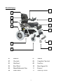
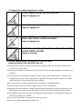
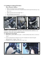
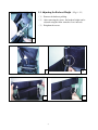
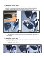
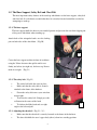
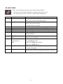
INSTRUCTION MANUAL
POWER STAND UP WHEELCHAIR
KARMAN HEALTHCARE INC.
City of industry, CA 91748
**Karman Healthcare Inc. Recommends Patient Seek Physicians Counsel Before Purchase
www.Activeforever.com
Table of Contents
P.3 XO-202: Parts Explanation
Chapter 1. SAFETY TIPS
1-1. Standing
1.2. Important symbols found on the vehicle
1-3. Safety information on driving and freewheel mode
1-4. Rear wheels
1-5. Armrests
1-6. Power drive attachments
1-7. Modifications
Chapter 2.
UNPACKING AND PREPARING THE STAND UP
WHEELCHAIR XO-202 STAND UP WHEELCHAIR FOR USE
2-1. The original package and accessories.
2-2. Unfolding the stand up wheelchair
Chapter 3. ADJUSTMENT
3-1. Adjusting the seat depth
3-2. Adjusting the backrest height
3-3. Adjusting the footrest height
3-4. Adjusting the footrest angle
3-5. The knee support and safety belt and chest belt
3-6. Adjusting the armrest height
3-7. The heel strap
3-8. Gas spring
3-9. The seat cushion
Chapter 4. DRIVING
4-1. Before Driving for the First Time
4-2. Taking obstacles
4-3. Driving up and down gradients
4-4. Free wheeling
Chapter 5. OPERATION THE STANDING AND SITTING
Chapter 6. CONTROL SYSTEM
6-1. The SHARK II Remote
6-2. Battery and control box connection
6-3. Battery charge
Chapter 7. MAINTENANCE & WARRANTIES
1
XO-202 Series
07
01
02
08
03
09
04
10
11
05
12
06
01
Backrest
07
Armrest
02
Chest belt
08
Controller Chest belt
03
Side Panel
09
Seat Rest
04
Rear Wheel
10
Knee Support Set
05
Motor/Differential Gear
11
Footrest
06
Front Wheel
12
Stand Up Casters
2
Chapter 1. SAFETY TIPS
Powered Chair Electromagnetic Interference (EMI)
WARNINGS
The following warning listed below should reduce the chance of unintended brake release or
powerchair movement, which could result in serious injury.
1. Do not operate hand-held transceivers (transmitter-receivers), such as citizens band (CB)
radios, or turn ON personal communication devices, such as cellular phones, while the
Powerchair is turned ON.
2. Be aware of nearby transmitters, such as radio or TV stations, and try to avoid coming close to
them.
3. In unintended movement or brake release occurs; turn the Powerchair OFF as soon as it is safe.
4. Be aware that adding accessories or components, or modifying the Powerchair may make it
more susceptible to EMI.
1-1. Standing
Attention:
•
Before you turn off the power wheelchair please make sure to wait for 10 seconds.
Otherwise, wheelchair seat may move up slightly but this is just the gas spring relieving
pressure.
•
Standing up stresses your body in ways you may not be used to. You should consult your
doctor or physical therapist before using the stand-up wheelchair.
•
Before using the stand up wheelchair you should be familiar with its operation and
functions.
•
•
•
Use only on hard even surface. Do not drive on wet surfaces.
In case of a staircase, the stand up wheelchair must be carried by 2 persons.
When riding on, standing with or leaving from the stand up wheelchair keep the user’s feet
firmly placed upon the footplates to avoid dangerous positions.
•
Before standing up it is absolutely vital that the knee support, safety belt and chest belt are
wrapped securely around the user.
WARNING:
Maximum weight limit should not exceed
XO-202: 250 lbs.
3
1-2.Important symbols found on the vehicle
DO NOT DRIVE OVER UNEVEN GROUND!
Danger of tipping over!
DO NOT LEAN OUT OF THE RAISED VERTICALIZER!
Danger of tipping over!
NEVER DRIVE ON ASCENDING OR DOWNWARD SLOPES
WHEN THE VERTICALIZER IS RAISED!
Danger of tipping over!
NEVER REACH INTO THE MOVING APPARATUS OF THE
RAISED VERTICALIZER!
Danger of crushing!
1-3 Safety Information on Driving and Freewheel Mode
Danger of injury if the wheelchair tips over
● Only negotiate gradients up to the maximum tilt-resistant gradient and only with the backrest and
seat tilt in a seated position.
● Only drive downhill at a maximum of 2/3 of the top speed! Avoid abrupt braking or acceleration on
gradients.
● If at all possible, avoid driving on slippery surface (such as gravel) where there is a danger of you
losing control over the vehicle, especially on a gradient! If driving on such a surface is inevitable,
then always drive slower and with the utmost caution.
● Never attempt to overcome an obstacle when on an uphill or downhill gradient!
● Never attempt to drive up or down a flight of steps with your wheelchair!
● Approach any and all obstacles straight on. Ensure that the front wheels and rear wheels move over
the obstacle in one stroke! Do not stop halfway! Do not exceed the maximum obstacle height!
● Avoid shifting your center of gravity, any abrupt joystick movements or swift changes of direction
when the wheelchair is in motion!
● Never use the wheelchair to transport more than one person!
● Do not exceed the maximum permissible load!
4
● Note that the wheelchair may brake or accelerate if you change the Driving Mode while the
wheelchair is in motion!
1-4. Rear Wheels
CURBS, INCLINES AND RAMPS
Always practice with your healthcare professional or attendant before attempting to negotiate
curbs, inclines or ramps alone. It is important for you to develop a safe technique that is suitable
to your abilities.
WARNING:
Doing a “wheelie” (tilting the wheelchair backward to its balance point) can be dangerous.
Do not attempt this maneuver without an attendant.
1-5. Armrests
Flip-back Armrests
Never lift the wheelchair by the flip-back armrests. These parts are detachable and lifting the
wheelchair by them may cause damage to the chair or injury to the user.
1-6. Power Drive Attachments
Karman Healthcare Inc. does not advocate any drive attachments on the XO-202 series
wheelchair. Use of a power drive attachment on XO-202 series wheelchair alters its intended use.
Installation of a power drive attachment is considered an alteration to the frame and
voids the warranty.
1-7. Modifications
Marking any unauthorized modifications or using parts not supplied by Karman Healthcare Inc.
may change the wheelchair structure and create an unsafe condition voiding the warranty.
This product has been supplied from an environmentally aware
manufacturer that complies with the Waste Electrical Equipment
(WEEE) Directive 2002/96/CE. Please be environmentally responsible
and recycle this product at the end of its life through your local recycling
facility. This product may contain substances that could be harmful to the
environment if disposed of into a landfill.
Chapter 2. UNPACKING AND PREPARING THE POWER STAND UP
WHEELCHAIR XO-202 SERIES FOR USE
2-1. List of Included Accessories and Components:
•
•
•
•
•
•
Power stand up wheelchair wheel strap & chest belt
Knee support
Charger (USA users check charger switch is set to 115VAC)
Oil pot
User Manual and Tool
Options as ordered
5
2-2. Unfolding the Stand up Wheelchair
Please Proceed as Follows:
•
•
Remove any transport straps or transport guards.
Grasp the wheelchair at the backrest and pull backward and then push downward up to stop.
(Fig. 1 & 2)
•
•
•
Tighten the knob on the left and right. (Fig. 3)
Press the flip-back armrest forward.
Connect the DC power line to power socket of battery.
1
2
3
Chapter 3. ADJUSTMENT
Should you require adjustments and alterations to the mechanism of the wheelchair, or any
maintenance work, please contact qualified technicians.
3-1. Adjusting the Seat Depth
(1)Pull upward(push forward on the joystick) and the wheelchair frame will rise over the rear
wheel.
(2)After loosening the left and right side screws the seat depth can be adjusted using the
different holes at 1” distance. (Fig- 4 ~ 6)
(3)Retighten the left and right both side screws.(Fig- 7 & 8)
4
5
6
3-2. Adjusting the Backrest Height (Fig-9 ~12)
(1) Remove the backrest padding.
(2) After removing the screws, the backrest height can be
adjusted using the Allen wrench at 2 cm. intervals.
(3) Retighten the screws.
7
9
10
11
12
7
3-3. Adjusting the Footrest Height
The height of the footrest is adjustable and should be adjusted to compliment your body
proportions to guarantee the best and most comfortable standing position possible. Footrest
adjustment should also take account of your choice of seat cushion. (Fig-13 ~ 16)
13
14
16
15
•
•
After loosening the screws the footrest height can be adjusted using the different holes at
1.8cm. intervals.
Retighten the screws.(not too tight)
3-4. Adjusting the Footrest Angle
•
•
After removing the screws the footplate angle can be adjusted using a different hole at 10°
incline angle. (Fig-17 & 18)
Retighten the screws.(Fig-19)
17
18
8
19
3-5. The Knee Support, Safety Belt and Chest Belt
The most important safety features of the stand-up wheelchairs are the knee support, safety belt
and chest belt. It is absolutely essential that these be correctly fastened around the user before
attempting to stand up.
3-5-1. The knee support
The knee support holds the knees in an extended posture and prevents the user from slipping out
of the power wheelchair when standing up.
Attach both of the triangular hooks over the locking
pins on both sides of the wheelchair.(Fig-20)
20
Center the knee support cushion in front of each knee
using the Velcro fasteners then pull it until it rests
firmly just below, (not right on), the knee cap. Do not
make it too tight. (Fig-21)
21
3-5-2. The safety belt(Fig-22)
•
•
The safety belt holds the waist in place.
Make sure that the safety belt is securely
attached to the frame of the backrest.
•
Fasten the safety belt across your waist but
not too tight.
•
To release the safety belt. Simply press the
red button in the center of the latch.
•
To slacken, hold the latch-end at a right
angle to the belt and pull.
22
3-5-3. Adjusting the chest belt(Fig-23 ~ 25)
•
•
Make sure that the chest belt is securely fastened to the frame of the backrest.
The chest belt holds the user’s upper body (chest) when in a standing position.
9
23
24
25
3-6. Adjusting the Armrest Height
(1) Release the left and right screws up to the clamp, they can be removed to suit desired
position.(Height 7”~10”) (Fig-26 & 27)
(2) Retighten the screws of the clamp.
26
3-7. The Heels Strap (Fig-28)
27
28
The purpose of the heel strap is to prevent the legs and feet from slipping backwards. It is fitted behind
the heels or higher. By making use of the Velcro fastening it is possible to alter the length of the strap
and ensure the best positioning for the feet on the footrest.
3-8. Gas Spring
The gas springs are specially designed to help hold your body weight in balance.
NOTE: Contents under pressure. Do not, under any circumstances take apart, puncture, apply
heat or fire!
3-9. The Seat Cushion
The Velcro fasteners prevent the cushion from slipping out of place even when you are standing
up. The height of the footrest should be adjusted to take into account the height of a given seat
cushion.
Once the knee support, safety belt and chest belt are fitted correctly you are
ready to stand up.
10
Chapter4. DRIVING
4-1 Before Driving for the First Time
Before you take your first trip, you should familiarize yourself well with the operation of the
vehicle and with all operating elements. Take your time to test all functions and driving modes.
Attention:
•
•
You are within easy reach of all operating controls.
The battery charge is sufficient for the distance intended to be covered.
4-2 Taking Obstacles
Your electric wheelchair is able to overcome obstacles and curbs to a maximum height of 4cm.
WARNING:
•
•
•
Never approach obstacles at an angle!
Put your backrest into an upright seated position before climbing an obstacle!
Never drive over obstacles that are elevated at odd and sharp angles. Always take care in
maneuvering any and all obstacles.
4-3 Driving Up and Down Gradients
Your electric wheelchair has a maximum tilt-resistant climbing ability of 17.6%.
WARNING:
•
Only drive downhill at a maximum of 1/2 of the top speed.
•
Avoid sudden changes of direction or abrupt braking when driving on slopes.
•
Always return the backrest of your seat or the seat tilt to an upright seated position before
ascending slopes. We recommend that you position the seat backrest or the seat tilt slightly to the
rear before descending slopes.
•
The standing position is only used for stationary ascension and not for simultaneous drive
operation. Return the wheelchair to a seating position before ascending a slope.
•
Never attempt to ascend or descend a slope on slippery surfaces or where there is a danger
of skidding.
•
Avoid trying to get out of the vehicle on an incline or a gradient.
•
Always drive straight in the direction the road or path you are on goes, rather than
attempting to zigzag.
•
Never attempt to turn around on an incline or a slope.
DANGER:
•
The standing position only serves positioning and not normal driving.
•
Never drive over uneven terrain, on an upward or downward slope obstacles when in the
standing position.
11
4-4 Free Wheeling:
Because the motors are designed to engage the electromagnetic brakes when the vehicle is not in
use or when the power is OFF. There is also a manual feature that allows them to “free-wheel”.
Free- wheeling is accomplished by pulling the free- wheeling levers to the free-wheeling position.
(Fig29)
29
WARNING:
• Never free-wheel your power wheelchair on a slope.
• Never free-wheel the motors while operating your vehicle.
• Always remember to engage the motors before turning the power back ON.
Chapter 5. OPERATION THE STANDING AND SITTING
1. First, adjust and secure the knee support and make sure that both triangular hooks of the knee
support lock over double-head screws of the frame. (Fig-30 & 31)
30
31
2. Attach the safety belt.(Fig-32)
3. Attach the chest belt.(Fig-33)
12
32
33
4. Pull upward(push forward on the joystick) and the wheelchair will go into stand up position.
5. Push downward(pull backward on the joystick) and the wheelchair will return to sitting position.
Caution:
•
•
Make sure your hand is not under the stand up mechanism.
Make sure there are no children behind or near the wheelchair.
Chapter 6. CONTROL SYSTEM
6-1. The SHARK II Remote
Introducing SHARK
SHARK heralds the dawn of new thinking in lower cost power chair control solutions. Using a
dedicated power module and control unit, SHARK has none of the compromises that go into the
design of one-box controllers - this means more power, unrivaled ergonomics, greater versatility and
superior usability.
•
Features Dynamic’s breakthrough “Chair Tamer” technology, providing unprecedented chair
performance, control and safety.
•
A number of control units are available to meet a wide range of user needs. These range from
optimally small, highly ergonomic units to units with a more traditional appearance and
standard functionality.
•
A choice of power modules offers basic ‘drive only’ functionality up through sophisticated
modules supporting multiple seat adjustments, lights, etc.
•
•
No heavy power cables running from the armrest to the motors and batteries.
No hot surfaces for the user to touch.
13
Using the Seat Function Button
(REMD11 & REMD21 Only)
1. Two seat functions are available for individual
adjustment and are accessed via the Seat Function
Button, (pictured at left). Seat Function 1 is “Stand-up
Mode” and Seat Function 2 is normal “Seat Mode.”
2. Press the Seat button once to toggle the control unit
from Drive mode to Seat mode. Seat Function 1 will be
active as noted by the amber colored “1” LED. Seat
Function 2 does not light up.
3. To adjust Seat Function 1, use the joystick
Forward/Reverse to Rise/Descend from standing
position.
14
Charging SHARK
Plug the battery charger into the charging socket located at the front of
the SHARK Control Unit.
The SHARK Battery Gauge will indicate the system is being charged
by cycling between a left-to-right chase and displaying the current
battery state-of-charge.
Driving is prevented (inhibited) while the system is being charged.
Once the Battery Charger displays a ‘full’ battery charge, the battery
charger plug may be removed.
If SHARK is turned off, or goes into sleep while charging, charging will continue.
Although the SHARK Information Gauge will display an approximate battery level
while charging, the Battery Charger should be used as the sole judge of charge
completion.
Assembly of the remote
1. Battery gauge
2. ON/OFF
3. Activate / connect through /
deactivate adjusting mode
4. Decrease speed
5. Speedometer
6. Horn
7. Increase speed
8. Attendant control LED
9. Service indicator LED
10. Joystick
Lower side
1. Combined charging socket /
programming socket
15
6-2. Battery and Control Connection
The main electrical control
system is composed of motor,
control box battery and
controller. The connection of
the control system is as
follows.
Stand up Motor
6-3. Charging Battery
1. First make sure that the battery charging line connects to the battery DC power socket and that
the line is connected correctly.
2. Connect the AC power line to the AC socket.(110~220V)
3. The light of the battery charger goes from yellow color to green color and represents the
battery’s charge.
When the battery capacity is low, it will stop working.
Attention:
1. Check the battery capacity before and after ever use.
2 . A new battery must be charged over 8 hours.
3. Charge your battery with the battery charger provided by manufacturer only.
6-4. Main Circuit Breaker (Only for your information, do not tamper with it)
The mean circuit breaker reset button is located on the battery box. (Fig. 31). The main circuit
breaker monitors the electric current drawn form the battery. It is a safety feature built into your
wheelchair for your safety. The entire electric system of the wheelchair is protected by the main
circuit breaker against overloading.
31
16
Chapter 7. MAINTENANCE
•
When cleaning your XO-202 series, use a dry or slightly moistened cloth to wipe the
wheelchair down. For stubborn or oily stains, apply a mild detergent to the cloth. Do not hose
down your XO-202 series with water.
•
Depending on the frequency of use, check tire pressure between once a week and once a
month. If necessary, pump up the tires in line with manufacturer’s recommendations.
•
Check the state of the tread on the tires every one to six months. If a tire is heavily or
unevenly worn, it should be replaced.
•
Every one to six months, check that the brakes still work reliably. Having applied the
brakes, the wheels should stop turning completely. If the brakes are ineffective, they should be
tightened up.
•
Depending on frequency of use, lubricate the knee joint between once a week to once a
month. (Fig-32~34)
32
33
WARNING!
To inspect or replace the motor brushes:
1. Unscrew the motor brush caps. (See Fig 35)
2. Remove the brushes.
3. Inspect the brushes for wear (See Fig 36)
4. Replace the brushes if necessary.
35
36
17
34
FLASH CODES
Flash codes indicate the nature of an abnormal condition
directly from the SHARK Information Gauge. Without the use of
any servicing tools, the condition can be simply diagnosed.
Flash Code
1
Description
User Fault
2
Battery Fault
Possible stall timeout or user error.
Release the joystick to neutral and try again.
Try charging the batteries.
Batteries may require replacing.
3
4
5
6
7
Left Motor Fault
Right Motor Fault
Left Park Brake Fault
Right Park Brake Fault
SHARK Remote Fault
8
SHARK Power Module
Fault
SHARK
Communications
Check the batteries and cabling.
Check the left motor, connections and cabling.
Check the right motor, connections and cabling.
Check the left park brake, connections and cabling.
Check the right park brake, connections and cabling.
Check the SHARK Communications Bus connections and wiring.
Replace the Remote.
Check SHARK connections and wiring.
Replace the Power Module.
Check Battery voltage is greater than 17V.
Check SHARK Bus Cable.
Fault
Replace the SHARK Power Module.
9
10
Unknown Fault
11
Incompatible Remote
Replace the SHARK Remote.
Check all connections and wiring.
Consult a service agent.
The Remote is incompatible with the Power Module.
Ensure the brand of the power Module matches that of the remote.
18
*****WARNING*****
This chair is not intended for those who have:
-Lower limbs joint contracture (absolute contra-indication)
-Total hip replacement (THR) and total knee replacement (TKR)
-Instability on lower extremity joints
-Severe osteoporosis on lower extremities
-Severe abnormal reflex (lower extremities withdraw reflex)
-Severe postural hypotension
-Low-shearing seat will be suggested to those who use positioning system
19
WARRANTIES
Frame
3 Years
Electrical
1 Year
Parts
Motor/Transaxle/Brake
6 Months
1 Year
1.
Structural frame components including platform, fork, seat post and frame welds are warranted, to the original owner/
2.
To present a claim, Customer shall deliver the defective part for exchange or repair if possible to an Authorized Karman
provider.
3.
This warranty is for the replacement or repair, at the option of Karman Healthcare Inc., of defective parts only and does
not cover any labor charges including, but not limited to, charges incurred for installation of replacement parts or
additional fees, which may be imposed by Karman Healthcare Inc.
4.
All warranty replacement parts are under warranty from the date of purchase of the original “product” and not from the
date of part replacement.
5.
This warranty is valid and enforceable only on “products” purchased in the United States and from a Karman provider.
6.
This warranty is applicable only to the customer as an original purchaser of the “product” from an Authorized Karman
provider and shall not apply to any subsequent purchaser, assignee or other recipient of the power chair from customer.
7.
No provider or other similar person has any authority to make any warranties or representations concerning Karman
Healthcare Inc. products, or to extend this warranty beyond the expressed terms contained within. Distributor assumes no
responsibility for any warranties beyond the expressed terms contained in the warranty. Customer releases and holds
distributor harmless from any claims stemming from any unauthorized representations.
8.
This warranty does not apply unless the Registration Card is signed completed and returned within thirty days (30) from
the date of purchase.
9.
Warranty Exceptions:
A.
Transaxle: In cases where there is an increase in the operational noise level, the warranty will not apply.
B.
Motor: If damage occurs as a result of not replacing motor brushes after heavy wear to brushes.
10. This warranty does not cover batteries or damage caused by battery leakage. The battery manufacturer covers warranty.
11. This warranty does not cover plastic covers; seat upholstery, tires, or armpads these are considered wear items.
12. All transportation costs and shipping damage incurred while submitting parts for repair or replacement are the
responsibility of the original purchaser.
13. This warranty does not apply to any injury, loss, defect or malfunction of the “product” or failure to function resulting
from any failure to operate or maintain “product” in accordance with the directions contained in the owners manual
provided by Karman; or any injury, loss, damage or malfunction, or failure to function resulting from any accident, acts of
God, alterations in the “product” by anyone other than the distributor, or misuse, unreasonable use, tampering, abuse, acts,
omissions, failure or negligence by anyone other than the manufacturer.
20