1
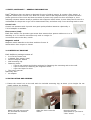
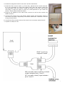
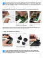
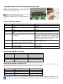
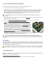
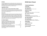
®
SafeDoor™
Door Exit Monitor with Nuisance Alarm Rejection
Operation and installation instructions
Warranty terms
Applicable model numbers:
Control unit D-1170-2G with
Floor sensor L-6090 and Magnetic Switch
For monitor device version t51 1.0.0.
EN
04.06.2009 V.2
TABLE OF CONTENTS
1. EMFIT® SAFEDOOR™ - GENERAL INFORMATION........................................................................................................... 2
2. CONTENTS OF PACKAGE............................................................................................................................................ 2
3. INSTALLATION AND WIRING...................................................................................................................................... 2
4. INSTALLING BATTERIES AND BATTERY CONSUMPTION ................................................................................................. 4
5. ABOUT THE OPTIONAL 5V AC ADAPTER....................................................................................................................... 4
6. SW1 SWITCH USE .................................................................................................................................................... 5
7. LED-Light indicators .................................................................................................................................................. 5
8. BEFORE USE SELECT THE RIGHT DIP SWITCH SSETTINGS ............................................................................................ 6
9. SYSTEM TEST AND SENSITIVITY ADJUSTMENT............................................................................................................. 7
10. CLEANING.............................................................................................................................................................. 7
11. TROUBLESHOOTING................................................................................................................................................ 7
12. IMPORTANT SAFETY NOTICES .................................................................................................................................. 8
13. MATERIALS DISPOSAL............................................................................................................................................. 8
14. EU / DECLARATION OF CONFORMITY ........................................................................................................................ 9
15. U.S. / FCC STATEMENT............................................................................................................................................ 9
16. CANADA / EMC COMPATIBILITY STATEMENT .............................................................................................................. 9
17. EMFIT LIMITED WARRANTY STATEMENT .................................................................................................................... 9
18. SPECIFICATIONS ...................................................................................................................................................11
19. MANUFACTURERS CONTACT INFORMATION ..............................................................................................................11
DANGER NOTES
THE FOLLOWING NOTES ARE PROVIDED FOR BOTH YOUR PERSONAL SAFETY AND TO PROTECT THE
DESCRIBED PRODUCT OR ATTACHED DEVICES FROM DAMAGE.
SAFETY NOTES AND WARNINGS FOR THE PREVENTION OF DANGER TO THE LIVES AND HEALTH OF
USERS OR MAINTENANCE PERSONNEL AND/OR FOR THE AVOIDANCE OF DAMAGE TO PROPERTY ARE
EMPHASISED IN THESE INSTRUCTIONS BY THE PICTOGRAMS DEFINED HERE. THE PICTOGRAMS
USED HAVE THE FOLLOWING MEANINGS FOR THESE INSTRUCTIONS:
Means that death, serious personal injury or substantial damage to property can occur if the
appropriate precautionary measures are not taken.
Means important information about the product or a part of the instructions that particular
attention should be paid to.
OTHER SYMBOLS USED
Use by
Upper storage temperature limit
All rights are reserved. Reproduction in whole or in part is prohibited without the written consent of the copyright owner. Our printed and electronically stored
literature is purely advisory and, therefore, we bear no legal responsibility for the information provided. We reserve the right to make changes and modifications
without prior notification in the interest of continual improvements of our systems and components.
1
1. EMFIT® SAFEDOOR™ - GENERAL INFORMATION
Emfit® SafeDoor door exit alarm is designed for care of elderly person. It consist a floor sensor, a
magnetic switch and a control unit. With use of floor sensor and magnetic switch, systems knows if
person goes out of the room and does not alarm if person only opens the door and stays in, thus
reducing nuisance alarms usually a problem with magnetic switch alone. A time delay can be used if it
is allowable for the person to go out for determined time, and alarm only if not returning back in time.
Control unit
Control unit operates with 2 pcs AA size good quality alkaline batteries. Optionally a
5 V DC adapter is available.
Floor sensor (mat)
Emfit floor sensor is a dynamic type sensor that senses when person walks over it or is
standing on it. It notices movement only and no weight. It
is mounted next to the door, inside.
Magnetic switch
Magnetic switch attaches to the door and door frame. It
senses when door is open or closed.
Picture 2.
2. CONTENTS OF PACKAGE
Emfit SafeDoor package consists of:
D-1170-2G control unit
L-6090SL floor sensor (mat)
SM-217 Magnetic Switch
Wall mounting clip
Fastening items
o 2 pcs 4 mm screws and locking anchors for fastening the mounting rack to the wall
o 4 pcs of screws for fastening the magnetic switch
o 4 pcs cord clips for wires
• This user’s manual
Optionally also:
AC adapter
3. INSTALLATION AND WIRING
1. Fasten the control unit to the wall with the included mounting clip, at about 1,8 m height. Do not
install outdoor the building.
Attach the wall mount with
the included two anchors
and screws
Slide the device into the
mount
Press the device
downwards so you hear a
“click” sound
2
2. Install the magnetic switch to the door and the doorframe.
3. Install the floor sensor inside (!) of the door, placed as the normal doormat.
It is very important to clean the surface from dust and stones. Place the
anti-slip pads under the sensor. Install the sensor to the floor with double
side tape, or tape the sides to avoid any small particles to get under the
sensor. Those easily break the sensor.
4. Plug the AC adapter to the mains and connect its cord to the control unit
PWR connector.
5. Connect the control unit to the facility alarm system and magnetic switch to
the control unit with a proprietary connection cable and Y-connector. See the
wiring picture below.
6. Connect the floor sensor wire to the control unit connector marked as X3.
7. System is ready for use.
PINS 7 and 8 for
magnetic switch
NO (normally open) type dry-contact
output between pins 1 and 2.
NC (normally closed) type between
pins 1 and 3.
3
DRY-CONTACT OUTPUT OF THE X2 (AUX) CONNECTOR CAN ONLY BE CONNECTED TO A SYSTEM
SAFETY VOLTAGE INPUT WITH MAX VOLTAGE BELOW 25V (AC) / 60V (DC), WHERE BOTH
POLES HAVE BEEN SEPARATED FROM THE ELECTRICAL NETWORK (SO CALLED FLOATING APPLIED
PART)! MAX LOAD CURRENT IS 100 mA.
4. INSTALLING BATTERIES AND BATTERY CONSUMPTION
Product operates with 2 pcs AA size 1.5 V alkaline batteries. Install and remove the batteries as
follows:
Open the cover by lifting
from one side
Install 2 pcs good quality AA
size 1,5 V alkaline batteries
according the polarity
drawings on the circuit board
When removing old
batteries, they are easiest
to remove by lifting from
+ ends
Estimated battery life is 6 months, when using high quality alkaline batteries, with 2800 mAh capacity
(2pcs). Estimation is based on measured battery consumption in various conditions and then a
calculation where device is on 50% of time and shut down 50% of time.
5. ABOUT THE OPTIONAL 5V AC ADAPTER
For preparing the optional power supply in use, do the following:
Remove the plastic cover
Pick up suitable adapter
from the included 4 pcs
Install the adapter and
make sure it stays in its
place
THE EMFIT SAFEDOOR IS DESIGNED AND TESTED TO BE USED ONLY WITH GLOBTEK INC.
POWER SUPPLY MODEL: NO GTM41060-1505 AND P/N:WR9QA3000LCP-N-MNK. ANY OTHER
TYPE OF AC ADAPTER MAY AFFECT THE PRODUCT’S SAFETY.
4
The power supply is equipped with a blue indicator light; when the light is on the power supply is in
use. If the light is off and the power supply is connected to the mains outlet, the power supply is
probably damaged and should be replaced.
WHEN THE AC ADAPTER IS CONNECTED TO THE POWER INPUT (X1), THE BATTERIES WILL
OPERATE AS BACK UP POWER SUPPLY IN CASE OF NO MAINS POWER. NOTE THAT ALL
BATTERIES DRAIN EMPTY UPON TIME. THEREFORE REPLACE BACK UP BATTERIES LATEST EVERY
SECOND YEAR. LOW BATTERY WARNING DOES NOT OPERATE WHEN AC ADAPTER IS CONNECTED.
TO TEST BATTERIES, SWITCH THE DEVICE ON AND REMOVE THE AC-ADAPTER CORD FROM X1. IF
THE RED LED LIGHTS UP, REPLACE THE BATTERIES.
6. SW1 SWITCH USE
Setting the device ON or OFF
Switch the device ON by pressing the SW1 switch about 3 sec. Blue
light starts blinking. The control unit is now in STANDBY mode.
Switch the device OFF by pressing the ON/OFF/RESET about 3 sec.
Blue light stops blinking.
Reset
When the notification has been triggered, the device resets by
person returning to the room or by pressing shortly the SW1 button.
Sound alarm silences by pressing shortly the SW1 button. If DIP
switch #3 is at ON position, systems resets automatically.
By-passing the exit notification
Nurse or other person can come in or go out without causing notification by pressing shortly the SW1
button. By-pass time is 20 seconds and during it the green led will blink.
Door-exit alarm delay
Emfit SafeDoor can be set to alarm only if the person leaves the room and does not return in and close
the door within a preset time. See chapter DIP switches.
7. LED-Light indicators
Green light
Blinking slowly, every second
time of blue light.
Blinking same time as blue light
Blinking fast (two times faster
than blue light)
Blinking very fast
Blue light
No light
Blinking
Blinking fast
Short period very fast blinking
Red light (fault)
Blinking slowly (every second
time of blue light)
Blinking same speed as blue light
Normal situation. System is
monitoring presence in room
By-pass time is going (20 sec)
Device has noticed door exit
and is counting delay as per is
set by DIP switches #1 and
#2.
System notices someone is
standing on the floor sensor
1. Green
2. Blue
3. Red
Device is turned OFF
Device is ON
Door is open
Notification is being triggered
Replace batteries
Floor sensor is detached or
broken
5
8. BEFORE USE SELECT THE RIGHT DIP SWITCH SSETTINGS
Inside the device there is a so called DIP
switch with 8 small switches. These are used
for various program settings.
See the following table and set up the
switches for your preferred way.
To open the device cover, see the picture on
right.
Table of DIP Switch Settings
Switch #
#1
#2
#3
#4
#5
#6
OFF (down)
Notification time delay setting, see next
chapter
Notification time delay setting, see next
chapter
Automatic reset disabled (not in use)
Intruder notification disabled (not in
use)
Dry-contact output is pulse mode (about
1 sec pulse)
Power switch function at SW1 is enabled
(device can be shut down and turned on
by pressing SW1 for about 3 seconds)
Notification sound volume setting, see
after next chapter
Notification sound volume setting, see
after next chapter
#7
#8
ON (up)
Notification time delay setting, see next
chapter
Notification time delay setting, see next
chapter
Automatic reset enabled (in use).
Intruder notification enabled (in use).
Dry-contact output is constant type. Use
only when necessary by other system to be
connected with. Not to be used with
batteries! Only with optional power supply
due increased power consumption.
Power switch function at SW1 disabled
(device is always on).
Notification sound volume setting, see after
next chapter
Notification sound volume setting, see after
next chapter
Setting the Notification Time Delay
Time Delay
Switch # 1
Switch #2
Shortest (6 sec)
OFF (down)
OFF (down)
15 minutes
ON (up)
OFF (down)
30 minutes
OFF (down)
ON (up)
60 minutes
ON (up)
ON (up)
Setting the Notification Sound Volume
The notification sound is useful only when caregiver is in close proximity to the control unit. The
volume can be adjusted at 4 levels: no sound, quiet, loud, and very loud.
Volume level
Very Loud
Loud
Quiet
No sound / mute
Switch # 7
OFF (down)
ON (up)
OFF (down)
ON (up)
Switch #8
OFF (down)
OFF (down)
ON (up)
ON (up)
ALWAYS UNPLUG THE AC ADAPTER AND REMOVE BATTERIES WHEN MAKING CHANGES TO THE
DIP SWITCH POSITIONS IN ORDER TO RESET THE PROGRAM AND GET THE NEW SETTINGS IN
USE.
6
9. SYSTEM TEST AND SENSITIVITY ADJUSTMENT
Make the following test after installation and at least every week when in use.
1. Inspect that all wires are on place and good condition.
2. Check that the floor sensor is positioned correctly, next to the door, inside. Check that anti-slip is
below the sensor. It is recommended that sensor is taped to the floor with double side tape to
prevent small particles get below the sensor and damage it. If sensor is not taped to the floor,
clean the bottom of the sensor and the floor with moist cloth to make sure there is no small
particles like stones that can puncture the sensor.
IT IS VERY IMPORTANT THAT THE ANTI-SLIP IS USED BELOW THE SENSOR TO AVOID IT
SLIPPING.
3. Check that the blued light is blinking and that green light does not blink when door is closed and no
person is standing on the sensor.
4. Check that blue light is blinking fast when door is opened but no one is on the floor sensor.
5. Check that green light is blinking fast when you stand still on the
sensor, for at least one minute. If it doesn’t stay on, adjust sensitivity
higher. It can be adjusted with rotary switch from the inside of the
device. Factory default setting is position #3. You need a small Phillips
head screwdriver for adjusting. Adjust it so that you stand still on the
floor sensor and device is in its bracket and not in hand. Turn the
sensitivity screw clockwise step by step until the green light is blinking
faster than blue light while you stand still on the sensor, not moving
(!). Minimum sensitivity is at #1 and maximum sensitivity at #9
position. Also, make sure that green light is blinking same speed as
blue light while you do not stand on the sensor and door is closed. If it
is blinking faster than blue light (sensitivity is set too high), turn the
sensitivity screw counter-clockwise step by step and until the green light blinks same speed as blue
light (door must be closed). Wait for a while at each step.
If the sensitivity is set too high, it will cause the green light blink faster than blue light even
though there is nobody on the sensor and thus the device will not function properly. Also, if it is
set for too low sensitivity, device will not function properly and may not trigger notification when
needed.
10. CLEANING
The floor sensor can be cleaned with water and, when necessary, neutral general-purpose or mild
antiseptic detergents. Always dry the sensor after cleaning. Use a moist cloth for cleaning the control
unit. Clean also the bottom of the sensor and the floor where it is being installed to avoid small
particles punch the sensor and cause a short.
THE CONTROL UNIT MUST NOT GET WET! DO NOT CLEAN THE AC ADAPTER OR THE CONTROL
UNIT WHEN IT IS CONNECTED TO THE MAINS OUTLET. ALWAYS DRY IT WELL AFTER CLEANING.
11. TROUBLESHOOTING
ALWAYS CHECK FIRST THAT INSTALLATION IS CORRECT AND TEST THE DEVICE PROPERLY AFTER
EVERY CHANGE (SEE SYSTEM TEST).
System alarm (relay output) does not work;
• Check that all the wirings are installed properly and they are in good condition
7
Sound alarm does not operate;
• Check the volume level.
False alarm alarms without reason:
• Make the system test (chapter 9).
No alarm at all even though such should have come:
• Make the system test (chapter 9).
Other possible problems: please contact your dealer, distributor or manufacturer directly.
ANY FEEDBACK TO MANUFACTURER IS HIGHLY APPRECIATED AND HELPS TO FURTHER DEVELOP THE
PRODUCT.
12. IMPORTANT SAFETY NOTICES
TO AVOID POSSIBLE INJURY OR DEATH:
• EMFIT SAFEDOOR IS NOT A LIFE SAVING SYSTEM
• KEEP THE EMFIT SAFEDOOR ELECTRONIC DEVICE AND SENSOR ALWAYS DRY. EXPOSURE TO
EXCESSIVE MOISTURE CAN CAUSE IT TO MALFUNCTION.
• READ INSTRUCTIONS PRIOR TO USE
• ALWAYS TEST THE SYSTEM PER INSTRUCTIONS PRIOR TO USE
• THIS PRODUCT MAY NOT BE SUITABLE FOR ALL PERSONS
• THIS PRODUCT SHOULD NOT BE A SUBSTITUTE FOR MAINTAINING THE ROUTINE VISUAL
MONITORING PROTOCOL BY CAREGIVER.
• MUST NOT BE USED IN SITUATIONS WHERE A DELAY IN THE ARRIVAL OF APPROPRIATE CARE
COULD LEAD TO A POTENTIALLY LIFE-THREATENING SITUATION.
• NEVER USE EMFIT SENSOR WITH OTHER MANUFACTURERS’ DEVICES.
• THE NOTIFICATION MAY FAIL TO SOUND IF THE SENSOR OR ITS WIRE IS DAMAGED OR
IMPROPERLY POSITIONED.
• PETS CAN CAUSE SYSTEM DO NOT GIVE NOTIFICATIONS OR GIVES FALSE NOTIFICATION.
• SENSOR MUST NOT BE SCRATCHED, SLIT OR CUT.
• CHECK SENSOR AND WIRES CONDITION AND IN USE TIME AT LEAST WEEKLY AND REPLACE WHEN
NECESSARY.
• DO NOT INTEGRATE TO OTHER SYSTEM OTHERWISE THAN SPECIFIED IN THIS MANUAL.
• DO NOT OPEN THE PARTS OR ATTEMPT TO REPAIR IT YOURSELF.
• ALWAYS KEEP THE CONTROL UNIT AND SENSOR DRY. EXPOSURE TO EXCESSIVE MOISTURE CAN
CAUSE IT TO MALFUNCTION.
• THE PRODUCT FULLFILLS THE REQUIREMENTS OF THE EMC-DIRECTIVE FOR MEDICAL DEVICES- IT
DOES NOT CAUSE ANY ELECTROMAGNETIC DISTURBANCE IN NORMAL WORKING CONDITIONS.
• THE PRODUCT CAN BE STACKED OR PLACED NEAR OTHER PRODUCTS OR DEVICES AS LONG AS
MECHANICAL VIBRATION IS NOT PRESENT.
• ALWAYS CHECK THE FUNCTION OF THE PRODUCT AFTER MAKING ADJUSTMENTS.
ACCIDENTIAL OR INTENTIONAL ADJUSTMENT OF KNOBS AND SWITCHES BY THE USER OR SUBJECT
MAY CAUSE:
• THE NOTIFICATION SOUND TO NOT ACTIVATE
• FALSE NOTIFICATIONS (INCREASE) OR MALFUCTION (DECREASE) WHEN ADJUSTING THE
SENSITIVITY.
• THE PRODUCT MAY NOT GIVE NOTIFICATION WHEN NECESSARY IF TURNED OFF BY PRESSING THE
SW1 SWITCH.
• THE PRODUCT MAY NOT GIVE NOTIFICATION WHEN NECESSARY WHEN SWITCHING DIP
SWITCHES.
13. MATERIALS DISPOSAL
These Emfit products contain the following materials that might require special handling when
disposed of:
- PVC
8
Disposal of this material can be regulated because of environmental considerations. For disposal or
recycling information, please contact your local authorities or the Electronic Industries Alliance (EIA,
www.eiae.org).
14. EU / DECLARATION OF CONFORMITY
Emfit SafeDoor™ alarm (product numbers D-1170-2G, L-6090SL and SC516) complies
with the requirements of EMC directive 2004/108/EC and CE mark directive 93/68/EEC
and carries the CE marking accordingly.
15. U.S. / FCC STATEMENT
The United States Federal Communications Commission has specified that the following notice to be
brought to attention of users of this product:
This equipment has been tested and found to comply with the limits for a Class A digital device,
pursuant to part 15 of the FCC Rules. These limits are designed to provide reasonable protection
against harmful interference when the equipment is operated in a commercial environment. This
equipment generates, uses and can radiate radio frequency energy and, if not installed and used in
accordance with the instruction manual, may cause harmful interference to radio communications.
Operation of this equipment in a residential area is likely to cause harmful interference in which case
the user will be required to correct the interference at his own expense.
CHANGES OR MODIFICATIONS NOT EXPRESSLY APPROVED BY THE PARTY RESPONSIBLE FOR THE
COMPLIANCE COULD VOID THE USER’S AUTHORITY TO OPERATE THE EQUIPMENT.
16. CANADA / EMC COMPATIBILITY STATEMENT
This Class A digital apparatus complies with Canadian ICES-003.
Cet appareil numériqué de la classe A est conformé à la norme NMB-003 du Canada.
17. EMFIT LIMITED WARRANTY STATEMENT
In the unlikely event that your product needs guarantee service, please contact your dealer, distributor
or manufacturer. To avoid any unnecessary inconvenience on your part, we recommend you read this
instruction manual carefully before seeking guarantee service.
YOUR GUARANTEE
By this Guarantee, Emfit guarantees the product to be free from defects in materials and workmanship
at the date of original purchase for a period of two (2) years from that date.
If within the guarantee period the product is determined to be defective (at the date of original
purchase) due to improper materials or workmanship, Emfit will, without charge for labour or parts,
repair or (at Emfit's discretion) replace the product or its defective parts subject to the terms and
limitations below. Emfit may replace defective products or parts with new or refurbished products or
parts. All products and parts replaced become the property of Emfit.
TERMS
1. Guarantee services will be provided only if the original invoice or sales receipt (indicating the date
of purchase, model name and dealer's name) is presented with the defective product within the
guarantee period. Emfit may refuse free-of-charge guarantee service if these documents are not
presented or if they are incomplete or illegible. This Guarantee will not apply if the model name or
serial number on the product has been altered, deleted, removed or made illegible.
9
2. This Guarantee does not cover transport costs and risks associated with transport of your product
to and from Emfit.
3. This guarantee does not cover:
a) periodic maintenance and repair or parts replacement due to wear and tear. Notice! Floor
sensor is easily damaged if small particles like stones get below it. Such damage is not covered by
guarantee.
b) consumables (components that are expected to require periodic replacement during the lifetime
of a product such as non-rechargeable batteries)
c) damage or defects caused by use, operation or treatment of the product inconsistent with
normal use
d) damage or changes to the product as a result of:
i. misuse, including:
- treatment resulting in physical, cosmetic or surface damage or changes to the product
- failure to install or use the product for its normal purpose or in accordance with Emfit’s
instructions on installation or use
- failure to maintain the product in accordance with Emfit’s instructions on proper maintenance
- installation or use of the product in a manner inconsistent with the technical or safety laws or
standards in the country where it is installed or used
ii. the condition of or defects in systems with which the product is used or incorporated except
other Emfit’s products designed to be used with the product
iii. use of the product with accessories, peripheral equipment and other products of a type,
condition and standard other than prescribed by Emfit
iv. repair or attempted repair by persons who are not Emfit employees
v. adjustments or adaptations without Emfit’s prior written consent, including:
- upgrading the product beyond specifications or features described in the instruction manual, or
- modifications to the product to conform it to national or local technical or safety standards in
countries other than those for which the product was specifically designed and manufactured
vi. neglect
vii. accidents, fire, liquids, chemicals, other substances, flooding, vibrations, excessive heat,
improper ventilation, power surges, excess or incorrect supply or input voltage, radiation,
electrostatic discharges including lighting, other external forces and impacts.
4. This guarantee covers only hardware components of the product.
EXCLUSIONS AND LIMITATIONS
EXCEPT AS STATED ABOVE, EMFIT MAKES NO WARRANTIES (EXPRESS, IMPLIED, STATUTORY OR
OTHERWISE) REGARDING PRODUCT OR ACCOMPANYING OR CONSTITUENT SOFTWARE QUALITY,
PERFORMANCE, ACCURACY, RELIABILITY, FITNESS FOR A PARTICULAR PURPOSE, OR OTHERWISE. If
this exclusion is not permitted or fully permitted by applicable law, Emfit excludes or limits its
warranties only to the maximum extent permitted by applicable law. Any warranty that cannot be fully
excluded will be limited (as far as permitted by applicable law) to the duration of this Guarantee.
EMFIT’S ONLY OBLIGATION UNDER THIS GUARANTEE IS TO REPAIR OR REPLACE PRODUCTS SUBJECT
TO THESE GUARANTEE TERMS AND CONDITIONS. EMFIT IS NOT LIABLE FOR ANY LOSS OR DAMAGE
RELATING TO PRODUCTS, SERVICE, THIS GUARANTEE OR OTHERWISE, INCLUDING - ECONOMIC OR
INTANGIBLE LOSSES - THE PRICE PAID FOR THE PRODUCT - LOSS OF PROFITS, REVENUE, DATA,
ENJOYMENT OR USE OF THE PRODUCT OR ANY ASSOCIATED PRODUCTS - INDIRECT, INCIDENTAL OR
CONSEQUENTIAL LOSS OR DAMAGE. THIS APPLIES WHETHER THAT LOSS OR DAMAGE RELATES TO:
IMPAIRED OR NON-OPERATION OF THE PRODUCT OR ASSOCIATED PRODUCTS THROUGH DEFECTS
OR UNAVAILABILITY WHILE WITH EMFIT, WHICH CAUSED DOWNTIME, LOSS OF USER TIME OR
BUSINESS INTERRUPTION INACCURACY OF OUTPUT FROM THE PRODUCT OR ASSOCIATED
PRODUCTS.
THIS APPLIES TO LOSS AND DAMAGES UNDER ANY LEGAL THEORY, INCLUDING NEGLIGENCE AND
OTHER TORTS, BREACH OF CONTRACT, EXPRESS OR IMPLIED WARRANTY, AND STRICT LIABILITY
(EVEN WHERE EMFIT HAS BEEN ADVISED OF THE POSSIBILITY OF SUCH DAMAGES).
Where applicable law prohibits or limits these liability exclusions, Emfit excludes or limits its liability
only to the maximum extent permitted by applicable law. For example, some countries prohibit the
exclusion or limitation of damages resulting from negligence, gross negligence, wilful misconduct,
deceit and similar acts. Emfit’s liability under this guarantee will in no case exceed the price paid for
the product, but if applicable law permits only higher liability limitations, the higher limitations apply.
10
YOUR LEGAL RIGHTS RESERVED
Consumers have legal (statutory) rights under applicable national laws relating to the sale of consumer
products. This guarantee does not affect statutory rights you may have nor those rights that cannot be
excluded or limited, nor rights against the person from whom you purchased the product. You may
assert any rights you have at your sole discretion.
18. SPECIFICATIONS
Control Unit
Model:
Operating voltage:
Connectors:
Dry-contact out:
Switches and controls:
Status indicators:
Alarm delay:
Preferred mounting:
Dimensions mm
Weight:
Color:
Case:
Enclosure protection:
D-1170-2G
5 V DC
X1 = DC in, X2 = dry-contact out and magnetic switch in, X3 = floor sensor
Max. 100 mA, 25 V AC or 60 V DC, NO or NC
SW1 = ON/OFF/RESET, inside 8 program DIP switches and 10 position
rotary switch for floor sensor sensitivity adjustment
3 LED lights
4 positions, from immediate (6 sec) to 1 hour
On the wall with included bracket
96 x 127 x 34 mm
110 g
White
Plastic
IP20
Floor sensor
Model:
L-6090SL
Placing:
Inside next to the door
Dimensions mm (W x H): 610 x 930 mm (24,0” x 36,6”)
Thickness:
2 mm (5/64”)
Weight:
1,9 kg (65,8 oz)
Surface material:
Plastic
Wire length:
3 m (9,84 ft)
Magnetic switch
Use normally closed (NO) type
19. MANUFACTURERS CONTACT INFORMATION
Emfit Ltd
Konttisentie 8
FI-40800 VAAJAKOSKI
FINLAND
Phone: +358-14-332-9000
Fax: +358-14-332-9001
Email: [email protected]
Internet: www.emfit.com
Copyrights:
Emfi, Emfit, Emfit logo and SafeDoor are either registered trademarks or trademarks of Emfit Ltd in
EU, USA, Japan and/or other countries. Copyright © 2002-2009 Emfit Ltd. All rights reserved.
Patented, patents pending. List of patents is available from manufacturer upon request.
11