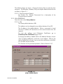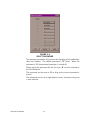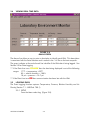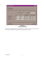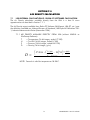
1
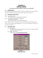
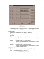
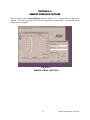
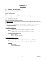
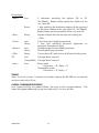
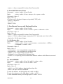
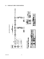
RUSKA MODEL 2456 LABORATORY ENVIRONMENT MONITOR USER’S MANUAL 2456 LABORATORY ENVIRONMENT MONITOR (LEM) USER'S MANUAL RUSKA INSTRUMENT CORPORATION 10311 WESTPARK DRIVE, HOUSTON, TEXAS 77042 (713) 975-0547 FAX (713) 975-6338 [email protected] Release: 2456-LEMCAL-1D01 Revision: D Date: 11/18/03 WARRANTY Ruska Instrument Corporation warrants its products to conform to or exceed the specifications as set forth in its catalogs in use at the time of sale and reserves the right, at is own discretion, without notice and without making similar changes in articles previously manufactured, to make changes in materials, designs, finish, or specifications. Ruska Instrument Corporation warrants products of its own factory against defects of material or workmanship for a period of one year from date of shipment. Liability of Ruska Instrument Corporation under this warranty shall be limited to replacing, free of charge (FOB Houston, Texas), any such parts proving defective within the period of this warranty, but will not be responsible for transportation charges or consequential damages. This warranty is not made for products manufactured by others which are illustrated and described in Ruska catalogs or incorporated in Ruska products in essentially the same form as supplied by the original manufacturer. However, Ruska Instrument Corporation agrees to use its best efforts to have original suppliers make good their warranties. -ii- INTRODUCTION COPYRIGHT NOTICE Copyright 2002 by Ruska Instrument Corporation. All rights reserved. This document may not be reproduced in part or in whole without the express written consent of Ruska Instrument Corporation. DISCLAIMER No representations or warranties are made with respect to the contents of this user's manual. Further, Ruska Instrument Corporation reserves the right to revise this manual and to make changes from time to time in the content hereof without obligation to notify any person of such revision. TRADEMARK NOTICE is a trademark of Ruska Instrument Corporation. Trademarks or tradenames are subject to state and federal laws concerning their unauthorized use or other infringements. The fact that the product marks or names in this manual do not bear a trademark symbol DOES NOT mean that the product name or mark is not registered as a trademark or tradename. Any queries concerning the ownership or existence of any trademarks or tradenames mentioned in this manual should be independently confirmed with the manufacturer or distributor of the product. -iii- INTRODUCTION REVISION NOTICE RELEASE NUMBER REVISION DATE OF REVISION 2456-LEM-1D01 A 06/25/02 Original release. 2456-LEM-1D01 B 09/09/02 Changes per DC/RO-23500. 2456-LEM-1D01 C 11/11/02 Changes per DC/RO-23601. 2456-LEM-1D01 D 11/18/03 Changes per DC/RO-24008 -iv- DESCRIPTION INTRODUCTION REVISION HISTORY RELEASE 2456-LEM-1D01 Original release. Revision A (06/25/02) RELEASE 2456-LEM-1D01 Changes per DC/RO-23500. Revision B (09/09/02) RELEASE 2456-LEM-1D01 Changes per DC/RO-23601 Revision C (11/11/02) RELEASE 2456-LEM-1D01 Changes per DC/RO-24008 Revision D (11/18/03) -v- INTRODUCTION WARNING PRESSURIZED VESSELS AND ASSOCIATED EQUIPMENT ARE POTENTIALLY DANGEROUS. THE APPARATUS DESCRIBED IN THIS MANUAL SHOULD BE OPERATED ONLY BY PERSONNEL TRAINED IN PROCEDURES THAT WILL ASSURE SAFETY TO THEMSELVES, TO OTHERS, AND TO THE EQUIPMENT. DO NOT USE HYDROCARBON LUBRICANTS. USE ONLY RUSKA INSTRUMENT CORPORATION SUPPLIED LUBRICANT, PART NUMBER 45339, UNLESS OTHERWSIE SPECIFIED IN THIS MANUAL. ALWAYS USE REPLACEMENT PARTS SPECIFIED BY RUSKA INSTRUMENT CORPORATION WHEN ANY MAINTENANCE IS PERFORMED, TURN OFF POWER AND REMOVE POWER CORD. -vi- INTRODUCTION TABLE OF CONTENTS WARRANTY ........................................................................................................... -iiCOPYRIGHT NOTICE ........................................................................................... -iiiDISCLAIMER ........................................................................................................ -iiiTRADEMARK NOTICE ......................................................................................... -iiiREVISION NOTICE .............................................................................................. -ivREVISION HISTORY ............................................................................................. -vWARNING ............................................................................................................ -viTABLE OF CONTENTS......................................................................................... -viiSECTION 1.0 FUNCTION 1.1 GENERAL FUNCTION.......................................................................1-1 1.2 COMPONENTS .................................................................................1-1 1.3 PC REQUIREMENTS ..........................................................................1-1 1.4 LEM BASICS ......................................................................................1-2 1.4.1 CALIBRATION DATA STORAGE .................................................1-2 1.4.2 MAIN COMM PORT ..................................................................1-2 1.4.3 POWER ....................................................................................1-3 SECTION 2.0 GETTING STARTED 2.1 INTERCONNECT ...............................................................................2-1 2.2 SOFTWARE INSTALLATION ..............................................................2-1 2.3 SOFTWARE SETUP ............................................................................2-1 2.3.1 HELP MENUS............................................................................2-1 2.3.2 SERIAL PORT SETUP ..................................................................2-1 2.3.2.1 Communications Protocol.............................................2-2 2.3.3 LEM ADDRESSING ....................................................................2-2 2.3.3.1 LEM.............................................................................2-2 2.3.3.2 LEMCAL Software.........................................................2-3 2.3.4 SELECTING A PRESSURE SOURCE .............................................2-3 2.3.5 SELECTING UNITS ....................................................................2-3 2.3.6 LIMITS ......................................................................................2-4 2.3.6.1 Setup ........................................................................2-4 2.3.6.2 Error Limit Logging ....................................................2-5 2.3.7 PASSWORD PROTECTION ........................................................2-5 2.3.7.1 Calibration Password .................................................2-5 2.3.7.2 Program Exit password...............................................2-7 2.4 VIEWING REAL TIME DATA ..............................................................2-8 2.5 LOGGING DATA ...............................................................................2-8 2.5.1 SETUP ......................................................................................2-8 2.5.2 INTERVALS ...............................................................................2-9 2.5.3 FILE NAMES..............................................................................2-9 2.5.3.1 Default Location.........................................................2-10 2.5.4 FILE VERIFICATION .................................................................2-10 2.6 MULTIPLE LEMS...............................................................................2-10 -vii- INTRODUCTION 2.6.1 CABLING ...............................................................................2-10 2.6.2 ADDRESSING .........................................................................2-10 SECTION 3.0 RUSKA 2456 & 2465 OPERATION 3.1 COMMUNICATIONS.........................................................................3-1 3.2 WINPROMPT INTERFACE..................................................................3-1 3.3 MODEL 2456 AND MODEL 2465 UPGRADE FOR LEM COMPATIBILITY ...............................................................................3-1 SECTION 4.0 REMOTE PRESSURE CAPTURE 4.1 USE WITH 7220 OR 6220.................................................................4-2 4.2 INITIALIZATION STRING ..................................................................4-2 4.2.1 6220........................................................................................4-2 4.2.2 7220 USING SCPI PROTOCAL ..................................................4-2 4.2.3 7220 USING 6220 EMULATION MODE ....................................4-2 4.3 PRESSURE STRING ............................................................................4-3 4.3.1 6220 AND 7220 IN EMULATION MODE ...................................4-3 4.3.2 7220 IN SCPI MODE ................................................................4-3 4.4 CABLING...........................................................................................4-3 4.4.1 6220........................................................................................4-3 4.4.2 7220........................................................................................4-3 4.5 USE WITH OTHER RS232 OUTPUT TRANSDUCERS .........................4-3 4.5.1 PROTOCOL..............................................................................4-3 4.5.2 SCALING..................................................................................4-4 4.5.3 COMMUNICATION PORT CONFIGURATION............................4-4 SECTION 5.0 CALIBRATION 5.1 SPAN ................................................................................................5-1 5.1.1 PRESSURE - ON BOARD SENSOR ..............................................5-1 5.1.2 TEMPERATURE ..........................................................................5-1 5.1.2.1 Zeroing .......................................................................5-1 5.1.3 HUMIDITY ................................................................................5-1 5.2 CALIBRATION DATA.........................................................................5-1 SECTION 6.0 CONNECTOR DEFINITION 6.1 POWER PLUG....................................................................................6-1 6.2 DB9 CONNECTORS ..........................................................................6-1 6.2.1 PRESSURE PORT........................................................................6-1 SECTION 7.0 AIR DENSITY CALCULATION 7.1 LEM INTERNAL CALCULATION VS. RUSKA PC SOFTWARE CALCULATION..................................................................................7-1 7.1.1 AIR DENSITY AVAILABLE DIRECTLY FROM LEM (without LEMCAL or WinPrompt Software) ............................................................7-1 SECTION 8.0 SPECIFICATIONS 8.1 SENSORS ..........................................................................................8-1 -viii- INTRODUCTION SECTION 9.0 APPENDIX 9.1 OPENING THE ENCLOSURE .............................................................9-1 9.2 REMOTE COMMANDS ......................................................................9-1 9.3 PRESSURE CONVERSION FACTORS .................................................9-7 9.4 RS485 MULTI-DROP CONFIGURATION ...........................................9-8 LIST OF FIGURES FIGURE 1-1 LEM GENERAL VIEW............................................................................1-2 FIGURE 1-2 LEM COMMUNICATION SWITCH........................................................1-3 FIGURE 2-1 FIGURE 2-2 FIGURE 2-3 FIGURE 2-4 FIGURE 2-5 FIGURE 2-6 FIGURE 2-7 FIGURE 2-8 FIGURE 2-9 SERIAL PORT SETUP ............................................................................2-1 VIEW COEFFICIENTS ..........................................................................2-2 OPTIONS ...........................................................................................2-3 UNITS ................................................................................................2-4 LIMITS ................................................................................................2-4 SELECT PASSWORD ............................................................................2-6 CHANGE EXIT PASSWORD ..................................................................2-7 MAIN SCREEN ....................................................................................2-8 DATA LOGGING ................................................................................2-9 FIGURE 4-1 REMOTE STRING SELECTION ..............................................................4-1 FIGURE 4-2 REMOTE STRING DIALOG...................................................................4-2 FIGURE 5-1 VIEW COEFFICIENTS ..........................................................................5-2 LIST OF TABLES TABLE 6-1 DB9 PINOUT ......................................................................................6-1 TABLE 9-1 PRESSURE CONVERSION FACTORS.....................................................9-7 -ix- INTRODUCTION SECTION 1.0 FUNCTION 1.1 GENERAL FUNCTION The Ruska Laboratory Environment Monitor (LEM) monitors the fundamental environmental parameters; Temperature, Pressure, and Relative Humidity. The sensor data is collected, processed, and made available on the selectable, RS232 or RS485, communication port. The data logging functions allow for easy collection, verification of data integrity and use of historical data. The LEM can be used as a stand alone device or in conjunction with other monitors. The monitor can also be used as the Air Density Monitor for the Ruska 2456 and 2465 models. If higher accuracy pressure data is needed, then a secondary RS232 communications port allows for use with Ruska 7220 / 6220 Portable Pressure Gauges and other pressure standards. 1.2 COMPONENTS The LEM product comes with the following accessories: 1 - Power Plug (input: 110-240 Vac, 50/60Hz) Ruska Part #62-315 1 - Communication Cable (F/F 9DSUB) Ruska Part #8-823 1 - Software Packet Ruska Part #2456-LEMCAL 1 - Manual Ruska Part #LEM-1D01 1.3 PC REQUIREMENTS Windows ™ 95, 98, 2000, or XP 130 MHz Pentium or higher 1-1 FUNCTION 1.4 LEM BASICS Local Pressure Port Serial Pressure Input Humidity Sensor Temperature Sensor Main Comm. Port Power Input Power Indicator Figure 1-1 LEM General View 1.4.1 CALIBRATION DATA STORAGE The calibration data is stored in the LEM. Refer to Section 5.0 for information on the Calibration process and how to access the coefficients. 1.4.2 MAIN COMM PORT The main communication port is user selectable for RS232 or RS485, using a switch located on the bottom of the LEM (see Figure 1-2). Cycle the power to activate a change in the communication port. The provided communication cable allows for the monitor to be directly connected to a standard PC - DB9 - RS232 port. FUNCTION 1-2 RS232 - C1 RS485 - C2 Figure 1-2 LEM Communication Switch Optional USB cables are available: RIC# 8-825 - USB to RS232 (requires Windows 98 or higher). 1.4.3 POWER The Power LED will illuminate when power is applied through either the power plug or the main communication port. Refer to Section 6.0 - Connector Specification - for connector and pin out details. 1-3 FUNCTION THIS PAGE INTENTIONALLY LEFT BLANK FUNCTION 1-4 SECTION 2.0 GETTING STARTED PC operation with Ruska LEMCal software and a single LEM 2.1 INTERCONNECT The standard interface cable for the LEM is a DB9 F/F cable (Ruska part number: 8-823) The green indicator light should come on when the power plug is connected. 2.2 SOFTWARE INSTALLATION Step 1. Insert CD into drive. The AutoRun function should begin the installation. Step 2. If the AutoRun function does not begin then Select Start and Select Run. Type D:\Setup (where D is your CDROM directory) Step 3. Double Click on the new LemCal icon in the Ruska Instrument Program group. At this point, the System should display data. If not, or if customization is desired, then continue with Section 2.3. 2.3 SOFTWARE SETUP 2.3.1 HELP MENUS The LEM software contains extensive help menus that provide detailed information about each function. 2.3.2 SERIAL PORT SETUP From the menu select Setup|Communication FIGURE 2-1 SERIAL PORT SETUP 2-1 GETTING STARTED The default settings are shown. Change the Comm Port to match the host computer. The Baudrate, Databits, Parity and Stopbit defaults should be set as shown in Figure 2-1. 2.3.2.1 Communications Protocol See Section 9.2 Remote Commands for a description of the Communication Protocol. 2.3.3 LEM ADDRESSING From the menu select Setup|Options 2.3.3.1 LEM The factory default address is 33. This address can be changed to any address between 0 and 99. The 0 address is the global address. When a command is issued with the 0 address all instruments on the communication bus will respond. To view the address and Calibration Calibrate|View Coefficients (Figure 2-2). Coefficients go to To change the address, double click on the Address Window, answer “Yes” to editing coefficients, and enter a new address. Click on the "Write Coefficients to Sensor" icon to write the coefficients to the LEM. This will take several seconds. This function can be password protected. Refer to Section 2.3.7. FIGURE 2-2 VIEW COEFFICIENTS GETTING STARTED 2-2 2.3.3.2 LEMCAL Software The factory default address is 33. The LEM and LEMCAL Software default to this Address. The LEMCAL Software needs the address set in the SETUP/OPTIONS screen of the LEM with which it will communicate. If this address is set to 0 then all LEMs on the communication bus will respond. FIGURE 2-3 OPTIONS 2.3.4 SELECTING A PRESSURE SOURCE From the Menu select Setup|Options Select the Local or Remote pressure sources for each enabled LEM by clicking on the appropriate column. The Local sensor location is shown in Figure 1-1 and specified in Section 8.0. Refer to Section 4.0 for description of the Remote Pressure function. 2.3.5 SELECTING UNITS From the Menu select Setup|Units. 2-3 GETTING STARTED FIGURE 2-4 UNITS Select desired units from the available choices for each environmental parameter. Changing units will also change the data written to the logfile. Refer to Section 2.5. 2.3.6 LIMITS From the Menu select Setup|Limits. FIGURE 2-5 LIMITS Select values for the upper and lower limits for Pressure, Temperature, and Relative Humidity. 2.3.6.1 Setup The Serial Number for the desired LEM is selected in the box in the top, left corner. Click the arrow, and the available LEMs will be displayed. When a specific instrument is selected, the current limits are displayed, and may be edited. The Audio Alarm is enabled by checking the Audio Alarm checkbox. This alarm generates a standard beep using the computer speaker. GETTING STARTED 2-4 The Visual Alarm is enabled by checking the Visual Alarm checkbox. This alarm is displayed on the main screen by changing the background color of the Serial Number to yellow whenever a limit is exceeded. The background will remain yellow until it is either disabled, or reset. Double-clicking the Serial Number will reset the visual alarm, but does not disable it. The Audio and Visual alarms can be set by double-clicking the message panel at the lower-left corner of the main screen, until the desired setting is selected. The limit values for one instrument may be copied to another instrument’s limit values, by using the Copy and Paste buttons. Closing the Limit form will erase values from the copy buffer. Pressing OK will check the new values for out-of-range and inconsistent values. If a problem is detected, an error message is displayed. Pressing CANCEL will leave the Limits unchanged. Pressing DEFAULT will return all limits, for the selected instrument, back to default values. 2.3.6.2 Error Limit Logging Crossing a limit value, will trigger a record being entered in the log file, if enabled. Refer to Section 2.5. 2.3.7 PASSWORD PROTECTION Two types of password protection are supported – Calibration and Program Exit. 2.3.7.1 Calibration Password From the Menu select Setup|Password|LEM 2-5 GETTING STARTED FIGURE 2-6 SELECT PASSWORD This password protection will prevent the changing of the calibration data and address. The default password is "0" (zero). When the password is "0" the password protection is turned off. When setting the password for the first time, "0" must be entered as the Old Password. The password can be reset to "0" as long as the current password is known. The password can be up to eight alpha/numeric characters long and is case sensitive. GETTING STARTED 2-6 2.3.7.2 Program Exit Password From the Menu select Setup|Password|Program Exit FIGURE 2-7 CHANGE EXIT PASSWORD This password protection will prevent closing LEMCal software. This is most useful when the Logfile function is being used, and a record without gaps is desired. The default password is "0" (zero). When the password is "0" the password protection is turned off. When setting the password for the first time, "0" must be entered as the Old Password. The password can be reset to "0" as long as the current password is known. The password can be up to eight alpha/numeric characters long and is case sensitive. 2-7 GETTING STARTED 2.4 VIEWING REAL TIME DATA FIGURE 2-8 MAIN SCREEN The Memo line allows a user to enter a descriptive to identify each LEM. This description is associated with the Serial Number and is stored in the *.ini file on the host computer. The green indicator at the end of each line identifies if the LEM data is being logged. See Section 2.5 for Data Logging *** If the Data Line turns YELLOW then the data being displayed is out of the following ranges: 17oC < temperature <29oC 0% < relative humidity < 100% 10 psi < pressure < 16.7 psi ED then communication has been lost with the LEM. *** If the Data Line turns RRED 2.5 LOGGING DATA The Data Logging function captures Temperature, Pressure, Relative Humidity and Air Density (Section 7.1 - NBS Pub. 700-1) 2.5.1 SETUP From the Menu select Log (Figure 2-8). GETTING STARTED 2-8 FIGURE 2-9 DATA LOGGING The Module number, in the left hand column, is referenced to each LEM as defined in Figure 2-3 and Figure 2-6. To begin logging data for a particular LEM, select the Enable button. 2.5.2 INTERVALS LEM data can be logged into a Day, Week, or Monthly file. Timing and date information are based upon the clock of the host computer. Day: Readings are taken at 1 minute intervals. The active file is saved and a new file is created at midnight of each day. Weekly: Readings are taken at 5 minute intervals. The active file is saved and a new file is created at midnight of each Saturday. Monthly: Readings are taken at 15 minute intervals. The active file is saved and a new file is created at midnight of the last day of each month. 2.5.3 FILE NAMES The file names are generated automatically using the following formats Day: SerialNumber_Year_Day of Year.LOG Example: SN054323_Y2002_D137.LOG 2-9 GETTING STARTED Week: SerialNumber_Year_Week of Year.LOG Example: SN054323_Y2002_W47.LOG Month: SerialNumber_Year_Month of Year.LOG Example: SN054323_Y2002_M05.LOG 2.5.3.1 Default Location By default, the log files are placed in C:\ Program Files \ Ruska Instrument \ LEM Cal \ LEMDataLog \. To change this location, select <Browse Dir> button - Figure 2-9. 2.5.4 FILE VERIFICATION From the Data Logging screen (Figure 2-9) select - Verify Log. Select the *.LOG file that needs to be verified. Upon completion of the verification a notice of verification will be displayed or a file *.ERR will be created and saved in the LOG directory. This file will identify which lines of the *.LOG file have been corrupted or altered. If any errors are detected then the corrupted lines are stored in a *.ERR file. 2.6 MULTIPLE LEMS The LemCal software supports up to 8 LEM modules at the same time when using RS485. Refer to selection 1.4.2 for selecting RS485 mode. 2.6.1 CABLING For MULTI-DROP SYSTEMS refer to Section 9.4 for available components. For custom cabling, refer to Section 6.2 for the pinout of the Main Communication Port on the LEM. 2.6.2 ADDRESSING Since the default address for each module is "33", each module will need to have its address set to a unique number between 0 and 100. This must be done with only one non-unique module on the communication bus at a time. Refer to Section 2.3.3. Each LEM must have a unique address and LEMCAL Software must be told which addresses are active on the communication bus. GETTING STARTED 2-10 SECTION 3.0 RUSKA 2456 & 2465 OPERATION WITH THE LEM 3.1 COMMUNICATIONS Set the communications interface to RS485 for use with the 2456 and 2465. Refer to Section 1.4.2 for LEM communication setup. Power for the LEM is supplied from the 2456 or 2465, over the communications cable. Use a standard DB9M / DB9F cable (Ruska PN: 8-826). 3.2 WINPROMPT INTERFACE Refer to the WinPrompt manual for detailed instructions. WinPrompt Version 2.12 or later is required. WinPrompt software calculates mass to pressure and pressure to mass values, and automatically displays real time piston gauge parameters measured by the Model 2456 Deadweight Gauge Monitor or the Model 2465 AutoFloat Controller. 3.3 MODEL 2456 AND MODEL 2465 UPGRADE FOR LEM COMPATIBILITY To upgrade a 2456/2465 from the original Air Density Model to the LEM, use Ruska part number 2465-200-KIT1 for all 2465's and the Single Channel 2456. Use Ruska part number 2465-200-KIT2 for the Dual Channel 2456. 3-1 OPERATION THIS PAGE INTENTIONALLY LEFT BLANK OPERATION 3-2 SECTION 4.0 REMOTE PRESSURE CAPTURE From the Menu select Setup|Options (refer to Figure 4-1). Set the Pressure Source as Remote. Click the extension arrows to the right of the selected LEM. The Remote String Dialog box will appear. FIGURE 4-1 REMOTE STRING SELECTION 4-1 REMOTE PRESSURE CAPTURE 4.1 USE WITH A RUSKA PORTABLE PRESSURE GAUGE 7220 OR 6220. FIGURE 4-2 REMOTE STRING DIALOG Initialization String Transmitted from LEM to remote pressure sensor to initialize the remote sensor. Pressure String Transmitted from LEM, on a continuous basis, to retrieve pressure readings. Remote Pressure Units Specifies the units that are being returned from the remote pressure sensor. The selection of the User units requires the entry of a conversion factor. The User units multiplied by the conversion factor results in kPa. (Refer to Section 9.3 for conversion factors.) 4.2 INITIALIZATION STRING 4.2.1 RUSKA MODEL NUMBER 6220 'UN,3\r' - This sets the units to kPa. 4.2.2 RUSKA MODEL NUMBER 7220 USING SCPI PROTOCOL 'UNIT:PRES KPA\r' This sets the 7220 to kPa units. 4.2.3 RUSKA MODEL NUMBER 7220 USING 6220 EMULATION MODE ':SYST:LANG "6220"\rUN,3\r' This sets the 7220 to 6220 emulation mode and to kPa units. Refer to the 6220 and 7220 manuals for other options. REMOTE PRESSURE CAPTURE 4-2 4.3 PRESSURE STRING 4.3.1 6220 AND 7220 IN EMULATION MODE. The pressure command string is 'PA\r'. 4.3.2 7220 IN SCPI MODE. The pressure command string is ':MEAS?'. 4.4 CABLING 4.4.1 RUSKA MODEL 6220 TO THE LEM PRESSURE SERIAL PORT 25 pin RS-232-C connector of the 6220 PIN DESCRIPTION 2 Transmitted data (to PPG) 3 Receive Data (from PPG) 4* RTS (must be set for PPG to transmit) 5* CTS (always set by PPG) 7 GND *Connect Pins 4 & 5 together. 6220 DB25 LEM DB9 2 3 3 2 7 5 Refer to 6220 Manual and Section 6.2 of this manual for additional information. 4.4.2 RUSKA MODEL 7220 TO THE LEM PRESSURE SERIAL PORT Requires a Null modem adapter or Null modem cable DB9 M / DB 9 F. Only Pins 2 and 3 must be swapped in the Null Modem cable. 4.5 USE WITH OTHER RS232 OUTPUT TRANSDUCERS 4.5.1 PROTOCOL The LEM can retrieve pressure data from other "smart" pressure sensors, as long as the return string can be parsed. The string returned to the LEM must be in ASCII characters. The LEM breaks down the returned string as follows: 1. Delete Prefix - all non-numeric characters are deleted up to the first numeric character. 4-3 REMOTE PRESSURE CAPTURE 2. The Exponent character (E or e) is located. 3. A one or two digit numeric exponent is read following the Exponent character. Examples of valid returned strings: 101.23 101.23kPa 1.0123E02 PA, 1.0123e02 kPa PA, 101.23 4.5.2 SCALING Once the raw value is retrieved from the string then units or a scaling factor must be given. Refer to Section 4.1 "Remote Pressure Units". 4.5.3 COMMUNICATION PORT CONFIGURATION This configuration applies only to the Remote pressure Input and is set as follows: BAUD RATE 2400 DATABITS 8 PARITY None STOPBITS 1 REMOTE PRESSURE CAPTURE 4-4 SECTION 5.0 CALIBRATION 5.1 SPAN 5.1.1 PRESSURE - ON BOARD SENSOR Calibration Point 1: 10.5 +/-0.25 psia Calibration Point 2: 15.0 +/-0.25 psia 5.1.2 TEMPERATURE Calibration Point 1: 17 +/- 2 degC Calibration Point 2: 29 +/- 2 degC 5.1.2.1 Zeroing Temperature measuring devices are impacted by self heating. The rise in temperature, measured by the sensor, is a function of the amount of heat generated by the probe and the ability of the probe to dissipate this heat. Air flow around the probe improves the heat dissipation and thus lowers the rise in temperature. When a temperature probe is calibrated in a high flow chamber and used in a low flow environment, then the error due to self heating is maximized. This error can be minimized by zeroing the sensor in the operating environment with respect to an appropriate standard. The LEM software allows the technician to perform a zero offset. The zero offset is prompted following the span calibration. After the span calibration is finished, the high air flow chamber can be turned off and the LEM can be zeroed in a low air flow environment that is typical of its operating environment. The reference probe should be placed at a distance of 3 or more inches in front of the LEM temperature sensor. Both the span calibration and zeroing operation are password protected. 5.1.3 HUMIDITY The humidity calibration must be done after the Temperature calibration. The two calibration points must be different by at least 25%RH. A suggested method: Point 1: applied vacuum -> 0%RH Point 2: ambient humidity (25%RH or higher) 5.2 CALIBRATION DATA In order to view the calibration coefficients, select Calibrate|View Coefficients. 5-1 CALIBRATION FIGURE 5-1 VIEW COEFFICIENTS The menu bar selections allow the coefficients to be read and written to disk and read and written to the LEM, assuming that the proper password is known. CALIBRATION 5-2 SECTION 6.0 CONNECTOR DEFINITION 6.1 POWER PLUG The power plug is a barrel type receptacle: ID = 2.5 mm, OD = 5.5 mm, Depth = 10.0 mm, Inside - Positive 6.2 DB9 CONNECTORS TABLE 6-1 DB9 PINOUT Pin #s DB9 1* 2** 3** 4 5 6 7 8** 9 DB9 male RS 485 +PWR IN A A GND-PWR GND-SIG NC NC B GND-PWR DB9 male RS 232 +PWR IN TX RX GND-PWR GND-SIG NC NC RX GND-PWR DB9 female (RS 232) NC RX TX GND GND NC NC NC GND *Supply pin (PIN 1 DB9 female) is fused with re-settable fuses. current is 50 mA. Maximum operating ** Pin 3 of the primary connector (DB9 male) is switched between Pins 2 and 8. This allows compliance with Ruska ER-3097 : "DB9-232/485-Pin Out Standard". 6.2.1 PRESSURE PORT The pressure port is a friction fit - press on tube connection. Motorola® package definition CASE 482A-01 Use Ruska tubing RIC# 86-1011 - 3mm ID tubing or equivalent. 6-1 CONNECTOR DEFINITION THIS PAGE INTENTIONALLY LEFT BLANK CONNECTOR DEFINITION 6-2 SECTION 7.0 AIR DENSITY CALCULATION 7.1 LEM INTERNAL CALCULATION VS. RUSKA PC SOFTWARE CALCULATION The Air Density calculation available directly from the LEM is a best fit curve approximation as described in Section 7.1.1. The Air Density output available from Ruska PC Software (WinPrompt, LEM PC, etc.) uses the definition available per National Bureau of Standards, NBS Special Publication 7001, Industrial Measurement Series (November 1984). 7.1.1 AIR DENSITY AVAILABLE DIRECTLY FROM LEM (without LEMCAL or WinPrompt Software). T = Temperature (16-bit integer, scaled °C*100) H = True RH (16-bit integer, scaled %*100) P = Pressure (16-bit integer, scaled kPa*100) D = Density (16-bit integer, g/m3) D= P *4916 − T * 2096 − 20 * H * 16 2 T + 273.15 46460 216 NOTE: Formula is valid for temperatures 18-28oC. 7-1 AIR DENSITY CALCULATION THIS PAGE INTENTIONALLY LEFT BLANK AIR DENSITY CALCULATION 7-2 SECTION 8.0 SPECIFICATIONS 8.1 SENSORS: Operating Range: Temperature: Pressure: Humidity: 18-28oC 690-1070 mbar (20.4 - 31.6 inHg) 5-95% RH Performance: Precision Temperature: Pressure: Humidity: Total Uncertainty: Temperature: Pressure: Humidity: +/-0.1oC +/-1.4 mbar (+/-0.04 inHg) +/-3% RH +/-0.5oC/year +/-2.7 mbar (+/-0.08 inHg)/year +/-10% RH/year Notes: (1) Precision is defined as the combined effects of linearity, repeatability and hysteresis. (2) Expression of accuracy (uncertainty) conforms with the recommendation of the ISO Guide to the Expression of Uncertainty in Measurement and includes RSS of precision, stability, temperature effects, and the calibration standard to 2 sigma (95%). The expanded uncertainty in the standards utilized by Ruska to calibrate the LEM is typically 0.1oC, 2.4% RH, 1.4e-3 kPa. Storage Environment: -20 - 70 ºC; 0 - 95% relative humidity, non-condensing Electrical Power: 10 - 30 Volt DC input; 250mA max Data Update Rate: New Data available at 1 second intervals. Temperature, Humidity, Pressure, Air Density. Includes Available Units: from Module : ºC x100, %RH x100, kPa x100, g/m3 from *.dll: ºC, %RH, kPa, g/m3 from PC Software : ºC, ºF; %RH; mmHg, cmHg, inHg, kPa, hPa, mbar, psi, kg/cm2; g/cm3, kg/m3, lb/in3 Warm up: Typically 30 minutes. 8-1 SPECIFICATIONS Placement: The proper orientations for the LEM are 1) Set flat on the table, sitting upon the rubber feet 2) Hanging on the wall with the temperature sensor pointing down. Calibration period: 1 year SPECIFICATIONS 8-2 SECTION 9.0 APPENDIX 9.1 OPENING THE ENCLOSURE Unplug power and communication cables. Remove the pressed in rubber feet. Remove the four screws. The top cover should come off easily. When installing the cover do NOT over tighten the screws. Tighten the screws just until the top and bottom covers meet. 9.2 REMOTE COMMANDS There are two general standards supported. The Binary protocol requires fewer bytes, therefore requiring less time to transmit each message. The Compatibility protocol requires more bytes per message, but allows the module to co-exist on the same RS485 bus with other DruckBus compatible components. DruckBus Binary Standard Command: &<Addr><Size><Cmd>[<Parm1>[<Parm2>...]]<Chk> Reply: %<Addr><Size><Cmd><Parm1>[<Parm2>...]<Chk> Example: (hexadecimal bytes) 26 01 01 56 70 25 01 05 76 02 03 04 CB 99 DruckBus Compatibility Standard Command: $<Addr><Size><Cmd>[<Parm1>[<Parm2>...]]<Chk>CR Reply: !<Addr><Size><Cmd><Parm1>[<Parm2>...]<Chk>CR Example: $01015670cr !010576020304CB99cr 9-1 APPENDIX Terminology: <Addr> Ascii 2 characters specifying the address (00 to 99, 00=Global). Replies always specify the address of the unit, never 00. Binary 1 byte specifying the destination address of the command or the source address of the reply (00 to FF, 00=Global). Replies always specify the address of the unit, never 00. <Size> Binary Number of bytes after the size byte not including the <Chk> <Cmd> Ascii Binary <Parm x> Ascii Binary 2 Ascii characters specifying command. 1 Ascii byte specifying command (Uppercase command, lowercase on reply). Variable-length Ascii formatted parameters. Fixed-length binary parameter. <Chk> Binary 1 binary byte LRC (exclusive-or of all bytes including start) CR Ascii Carriage Return required Compatibility Carriage Return required <start> Start on Binary mode Command = '&' ; Reply = '%' Compatibility mode Command = '$' ; Reply = '!' TIMING Slaves must wait at least 1 character time before replying (for RS-485 line turnaround) and must reply within 50 ms. GLOBAL COMMAND RESPONSES Units respond to Zero, the global address, the same as their assigned address. This means that global addressing can be used when only 1 unit is on the bus. APPENDIX 9-2 DruckBus Binary Mode Commands (Commands may be translated to Compatibility Mode for transmission) @ - Set Address Command: <start><addr><Size>@<NewAddr><Model><Value><Chk> Reply: None. Command <Size>: 8 <NewAddr> is an 8-bit unsigned number. <Model> is a 2-byte integer containing the model number, least significant byte first. <Value> is a 4-byte integer specifying a pressure in kPa * 100 or a serial number, least significant byte first. Normally, this command is sent using the global address. This command sets the address of the unit to the specified address with the following conditions: 1. If the model number and value are both zero, all units receiving this command will set their address. 2. If the model number in the command is not zero and the model number of the unit matches the specified model, the address is set. 3. If the model number matches and if the pressure specified in the command is not zero and the full scale pressure of the unit is greater than, or equal to, the specified pressure and the current address of the unit is 254 or 255, the address is set. 4. If the model number is zero, and a non-zero value is specified, and the value matches the serial number of the unit, the address is set. These conditions allow for the addresses of each different model to be set individually and the units of the same model to be set by pressure range. If two units have the same model and pressure range the address can still be set by serial number. A – Read ADC Counts Command: <start><addr><Size>A<chk> Reply: <start><addr><Size>a<status><temp><rh><pressure><chk> Command <Size>: 1 Reply <Size>: 10 <status> is three unsigned 8-bit values. Status1: Bit 0: ADC channel 0 Extended Input Range Indicator (EXR0) 0: 0 < Vin <= Vref 1: Vin > Vref or Vin < 0 Bit 1: ADC channel 0 Sign Indicator (SIG0) 0: Vin < 0 1: Vin > 0 Bit 2: ADC channel 1 Extended Input Range Indicator (EXR1) Bit 3: ADC channel 1 Sign Indicator (SIG1) Bit 4: ADC channel 2 Extended Input Range Indicator (EXR2) 9-3 APPENDIX Bit 5: ADC channel 2 Sign Indicator (SIG2) Bit 6: ADC channel 3 Extended Input Range Indicator (EXR3) Bit 7: ADC channel 3 Sign Indicator (SIG3) Status2: Bit 0: 1 = Calibration in Progress Bit 1: 1 = Zero in Progress Bit 2: 1 = Remote Port Selected (v1.4) Bit 3-7: Reserved Status3: Bit 0: 1 = Command Error Bit 1: 1 = EEPROM Write Error Bit 2: 1 = EEPROM Read Error Bit 3: 1 = Power-on Reset Bit 4: 1 = RS232 Receive Error Bit 5: 1 = Calibration Error Bit 6: Reserved Bit 7: 1 = Long (multiple) EEPROM accesses <temp> is a 16-bit unsigned value <rh> is a 16-bit unsigned value <pressure> is a 16-bit unsigned value C – Configure Instrument Command: <start><addr><Size>C<cfgByte><chk> Reply: <start><addr><Size>c<cfgByte><chk> Command <Size>: 2 Reply <Size>: 2 Defines which pressure source to use. <cfgByte> is an 8-bit unsigned value. <cfgByte> =0 No pressure source selected =1 Local pressure =2 Auxiliary pressure =3 Remote pressure = 254 Load LEM Memory from eeprom = 255 Poll for currently selected pressure source D – Read Air Density Command: <start><addr><Size>D<chk> Reply: <start><addr><Size>d<status><density><chk> Command <Size>: 1 Reply <Size>: 6 <status> is three unsigned 8-bit values. (See Command A) Returned data is a 16-bit unsigned value, least significant byte first. APPENDIX 9-4 E – Read EEPROM Command: <start><addr><Size>E<addr1><chk> Reply: <start><addr><Size>e<data><chk> Command <Size>: 3 Reply <Size>: 9 <addr1> is 16-bit address, least significant byte first.<data> is 8 bytes read from EEPROM. To read the eeprom, set the high byte of <addr> to 00H To read low memory, set the high byte of <addr> to F0H To read extended memory, set the high byte of <addr> to F1H. Address should be an 8-byte boundary. K - Calibrate Command: <start><addr><Size>K<channel><point><value><chk> Reply: <start><addr><Size>k<status><counts><chk> Command <Size>: 5 Reply <Size>: 6 <channel> and <point> are 8-bit values. <channel> selects channel to be calibrated. P for pressure, H for humidity, T for temperature. <point> is 1 for first point, 2 for second point. <value> is a 16-bit signed integer using scaled (*100) units matching select channel. <status> is three unsigned 8-bit values. (See Command A) <counts> is an unsigned 16-bit value. P – Set Initialization and Remote Pressure Strings Command: <start><addr><Size>P<seq><strlen><strseq><chk> Reply: <start><addr><Size>p<status><chk> Command <Size>: 11 Reply <Size>: 4 <seq> identifies which 8 byte substring is being transmitted. Acceptable Values for the Remote String are 0, 1, 2. Acceptable Values for the Initialization String: 3, 4, 5. <strlen> is the actual length of the command string, in bytes, that will be transmitted from the LEM to the remote pressure sensor over the software serial port. Acceptable values: 1-24. <strseq> is an 8 byte section of the string to be transmitted. The string to be transmitted must be 24 characters long, using a pad character to fill out the string. The first eight bytes are transmitted with <seq> set to 0 for the Remote Pressure string and 3 for the Initialization string, the middle eight bytes are transmitted with <seq> set to 1 for the Remote Pressure string and 4 for the Initialization string, and the last eight bytes are transmitted with <seq> set to 2 for the Remote Pressure string and 5 for the Initialization string. All three <seq> substrings for each string must be transmitted in sequential order. Either string may be updated without updating the other. 9-5 APPENDIX <status> is three unsigned 8-bit values. (See Command A) R - Read ADC Reference Values Command: <start><addr><Size>R<chk> Reply: <start><addr><Size>r<temp><rh><press><chk> Command <Size>: 1 Reply <Size>: 7 All values are 16-bit signed integers using scaled (*100) units. <temp> is degrees C <rh> is % <press> is kPa. S - Read Remote Pressure with Displayed Precision Command: <start><addr><Size>S<chk> Reply: <start><addr><Size>s<status><press><decimals><chk> Command <Size>: 1 Reply <Size>: 9 <status> is three unsigned 8-bit values. (See Command A) <press> is 32-bit unsigned integer using scaled (*10^decimals) units. Units is kPa. <decimals> is 8-bit signed integer V - Get Version Info Command: <start><addr><Size>V<chk> Reply: <start><addr><Size>v<versionmajor><versionminor><HWVer> <SubModel><model><chk> Command <Size>: 1 Reply <Size>: 7 <versionmajor> is an unsigned 8-bit unsigned value <versionminor> is an unsigned 8-bit unsigned value <HWVer> is an unsigned 8-bit unsigned value <SubModel> is an unsigned 8-bit unsigned value <model> is a 2-byte flag used to differentiate between software with different command sets. W - Write EEPROM Command: <start><addr><Size>W<addr1><data><chk> Reply: <start><addr><Size>w<data><chk> Command <Size>: 11 Reply <Size>: 9 <addr1> is a 16-bit address, least significant byte first. <data> is 8 bytes read from EEPROM. To write the eeprom, set the high byte of <addr> to 00H. To write low memory, set the high byte of <addr> to F0H. To write extended memory, set the high byte of <addr> to F1H. APPENDIX 9-6 Address should be an 8-byte boundary. Z - Zero Command: <start><addr><Size>Z<channel><value><chk> Reply: <start><addr><Size>z<status><counts><chk> Command <Size>: 4 Reply <Size>: 6 <channel> is an 8-bit value. <channel> selects channel to be calibrated. P for pressure, H for humidity, T for temperature. <value> is a 16-bit signed integer using scaled (*100) units matching select channel. <status> is three unsigned 8-bit values. (See Command A) <counts> is an unsigned 16-bit value. 9.3 PRESSURE CONVERSION FACTORS TABLE 9-1 PRESSURE CONVERSION FACTORS units mbar hpa kpa Kg/cm2 mmHg @ 0oC cmHg @ 0oC inHg @ 0oC x (multiplier) 0.01450377 0.01450377 0.1450377 14.223343 0.0193368 0.193368 0.491154 9-7 = units psi psi psi psi psi psi psi APPENDIX RS485 MULTI-DROP CONFIGURATION RS485 HARDWARE CONFIGURATION 9.4 APPENDIX 9-8