1
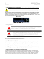
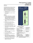
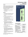
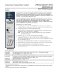
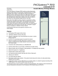
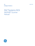
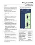
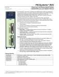
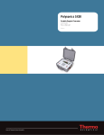
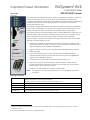
Important Product Information PACSystems* RX3i IC695PNS001-ABAH RX3i PROFINET Scanner GFK-2738H May 2015 The PACSystems* RX3i PROFINET Scanner module, IC695PNS001 or PNS001, connects a remote universal RX3i I/O rack of Series 90-30 or RX3i modules to a PROFINET I/O Controller. The PROFINET Scanner scans the modules in its rack, retrieving input data and providing output data, and exchanges that data on the PROFINET I/O LAN at the configured production rate. The PNS001 manages PROFINET communication and module configuration between an I/O Controller and modules in the remote rack. If network communications are lost, the PNS001 manages I/O states according to the individual module configurations. The PNS001 supports 10/100/1000 Mbps Copper, 100/1000 Mbps Multi-mode Fiber, and 100/1000 Mbps Single-mode Fiber. PROFINET communications on the network require 100 or 1000 Mbps link speed. Although 10 Mbps cannot be used for PROFINET communications, 10 Mbps can be used for other types of Ethernet traffic such as PING. Features of the RX3i PNS001 include: ▪ Configuration services for all supported Series 90-30 and RX3i I/O Modules using Proficy* Machine Edition (PME). For a list of currently supported I/O modules, refer to Supported Modules, Power Supplies and Backplanes. ▪ Support for daisy-chain/line, star, or ring (PROFINET Media Redundancy Protocol (MRP)) topologies. ▪ Four switched Ethernet ports - two 8-conductor RJ-45 shielded twisted pair 10/100/1000 Mbps copper interfaces and two Small Form-factor Pluggable (SFP) cages for user-supplied SFP devices. ▪ ▪ The network can include media interfaces of more than one type. Support for transfer of I/O Device Name to another PNS001 module using an SD card. This eliminates the need to connect a configuration tool, such as Proficy Machine Edition when replacing a module. ▪ A USB port for field updates of firmware using WinLoader. Note: The USB port is for firmware upgrades only. It is not intended for permanent connection. Ordering Information IC695PNS001 PACSystems RX3i PROFINET Scanner Module 10/100/1000 with four Ports (two SFP connections, two Copper) Includes a blank SD card, two mounting screws and a USB port cover IC695SPC100 RX3i 10/100/1000Base-T copper SFP IC695SPF002 RX3i 100Base-FX (fiber 2 km) SFP (Multi-mode fiber - MMF) IC695SPF550 RX3i 1000Base-SX (fiber 550 m) SFP (MMF) IC695SPF010 RX3i 1000Base-LX (fiber 10 km) SFP (Single-mode fiber - SMF) Indicates a trademark of General Electric Company and/or its subsidiaries. All other trademarks are the property of their respective owners. © 2013-2015 General Electric Company. All Rights Reserved. * 2 RX3i PROFINET Scanner GFK-2738H IC695PNS001-ABAH Specifications: PNS001 PROFINET Support PROFINET Version 2.3 Class A I/O Device Redundantly controlled operation implements PROFINET V2.3 Type S-2 System Redundancy Proficy Machine Edition Version Required Version 8.50 SIM 2 or later Power Requirements 3.3 Vdc: 1.2 A with no SFP devices installed 1.9 A maximum (two SFP devices installed, 0.35A per SFP) 5Vdc: 1.1 A maximum Operating Temperature Range 0 to 60°C Derated to 57°C: • If 100MB Fiber SFPs installed, or • If Copper SFPs operating at 1GB Two RJ-45 and Two SFP Cages (SFP devices not included, available separately.) Number of Port Connectors USB Connector (for firmware One Micro-B connector. USB 2.0 compliant running at Full-speed (12 MHz) upgrades) SD Card Supports SD and SDHC cards. PNS001 Status and Control 32 input status bits and 32 output control bits Bits PROFINET I/O production rate (I/O Update Rate) Configurable selections: 1 ms, 2 ms, 4 ms, 8 ms, 16 ms, 32 ms, 64 ms, 128 ms, 256 ms or 512 ms Number of IP addresses One. Supports Classless Inter-Domain Routing (CIDR) Number of MAC Addresses Five. One per external port and one internal. I/O Station Maximum Limits Number of I/O Modules per Number of backplane slots minus one for station PNS001 and at least one for a power supply I/O data per station Configuration 2880 bytes total 1440 bytes of input data 1440 bytes of output data V2.3 GSDML file is available on the Support website http://support.ge-ip.com for download and import into Proficy Machine Edition. The GSDML supporting a firmware release is part of the firmware upgrade kit available on the Support website. For product standards, general operating specifications, and installation requirements, refer to PACSystems RX3i System Manual, GFK-2314. RX3i PROFINET Scanner IC695PNS001-ABAH 3 GFK-2738H Installation Location This product is intended for use with the RX3i system. Its components are considered open equipment (having live electrical parts that may be accessible to users) and must be installed in an ultimate enclosure that is manufactured to provide safety. At a minimum, the enclosure shall provide a degree of protection against solid objects as small as 12mm (fingers, for example). This equates to a NEMA/UL Type 1 enclosure or an IEC60529 IP20 rating providing at least a pollution degree 2 environment. For details about installing RX3i rack systems, refer to PACSystems RX3i System Manual, GFK-2314. Installation in Hazardous Areas The following information is for products bearing the UL marking for Hazardous Areas or ATEX marking for explosive atmospheres: CLASS 1 DIVISION 2 GROUPS ABCD This equipment is an open-type device and is meant to be installed in an enclosure suitable for the environment that is only accessible with the use of a tool. Suitable for use in Class I, Division 2, Groups A, B, C and D Hazardous Locations, or nonhazardous locations only. Warning – EXPLOSION HAZARD - SUBSTITUTION OF COMPONENTS MAY IMPAIR SUITABILITY FOR CLASS I, DIVISION 2. Warning – WHEN IN HAZARDOUS LOCATIONS, TURN OFF POWER BEFORE REPLACING OR WIRING MODULES. ATEX Zone 2 This module must be mounted in an enclosure certified in accordance with EN60079-15 for use in Zone 2, Group IIC and rated IP54. The enclosure shall only be able to be opened with the use of a tool. 4 RX3i PROFINET Scanner GFK-2738H IC695PNS001-ABAH PROFINET Scanner Status and Control Data The RX3i PROFINET Scanner provides 32 bits of input status data and receives 32 bits of output control data. The application program in the I/O Controller system can monitor the input status bits for the PNS001 module. The output control bits are reserved for future use and have no function at this time. Output Control Bits: The PROFINET Scanner’s 32 bits of control output are reserved for future use. Input Status Bits The PROFINET Scanner’s 32 bits of input status provide information about the scanner. All status bits are active high. Status Bits Name Description 1 Module OK Indicates the health of the module. A value of 0 indicates the module is powering up or has failed. A value of 1 indicates the module is functioning properly. 2 Reserved Set to 0 3 Port1 Link Up 4 Port2 Link Up 5 Port3 Link Up 1 = port is connected to another device and is communicating. 0 = port is not connected to another device, or the port has some sort of error preventing communications. 6 Port4 Link Up 7-10 Reserved Set to 0 11 MRP Enabled Indicates whether MRP has been enabled or not. A value of 0 indicates that MRP is not enabled. A value of 1 indicates that MRP is enabled. 12 MRP Role Indicates the MRP role the PNS001 is operating as when MRP is enabled. A value of 0 indicates that the PNS001 is currently an MRP Client. A value of 1 indicates that the PNS001 is currently an MRP Manager, however the PNS001 does not currently support MRP Manager configuration. If MRP is not enabled, then this bit will be set to zero. 13-32 Reserved Set to 0 RX3i PROFINET Scanner 5 IC695PNS001-ABAH GFK-2738H LEDs on the PROFINET Controller Module Power-Up LED Patterns At power-up, the LEDs show the patterns described in the following table. The LEDs also blink diagnostic patterns for certain operating errors and for module identification. Step LED/ Blink pattern Description 1 All LEDs off Initial state 2 STATUS LED solid green Normal operation OK LED blinks amber with special blink code Fatal initialization or diagnostics failure; H/W Module Identity Information not available STATUS LED blinks amber with special blink code Fatal initialization failure. OK, LAN, and STATUS LEDs blink green in unison (0.5 second ON/ 0.5 second OFF) Invalid firmware detected or firmware update initiated. Module is waiting for firmware update. Blink pattern continues during firmware update. After the automatic update completes, the LAN and STATUS LEDs blink amber and the module resets, which restarts the powerup process. STATUS and LAN LEDs blink green in unison (0.5 seconds ON/ 0.5 seconds OFF) Internal update in process following a firmware update. Unit should complete update and restart automatically. 3 LAN and STATUS LED solid green Normal operation 4 OK LED solid green Normal operation. Power-up completed. Note: Under certain ambient operating temperatures, the PROFINET Scanner could momentarily display the over temperature pattern during power up, while it is calibrating its thermal protection functions. This indication can be ignored. For details, refer to the section entitled Microprocessor Over-Temperature in PACSystems RX3i PROFINET Scanner Manual, GFK-2737. 6 RX3i PROFINET Scanner GFK-2738H IC695PNS001-ABAH Normal Operation of Individual LEDs The PNS001’s LEDs can operate in tandem to indicate fatal error, module location/identification, microprocessor over-temperature, and update conditions. For details on these blink patterns, refer to PACSystems RX3i PROFINET Scanner Manual, GFK-2737. OK LED The OK LED indicates whether the module is able to perform normal operation. Green, on OK Off Not OK LAN LED The LAN LED indicates access to and activity on the Ethernet network. The LAN LED indicates network packets are being processed by the network interface (not just passing through the embedded switch). Blinking on The module’s network interface is active Off No activity STATUS LED The STATUS stays Green during normal operation. Green, on Normal Operation Red, blinking A MAC address read from nonvolatile memory is invalid. Ports with invalid MAC addresses remain disconnected from the Ethernet network. CONN LED The CONN LED indicates the status of PROFINET connections. Green, on At least one PROFINET connection (AR) exists with an I/O Controller. Amber, blinking No device name configured. Off No PROFINET connection (AR) exists. Port LEDs The PROFINET Controller has four Port LEDs, PORT1, PORT2, PORT3, and PORT4 that indicate link speed, link connection and link activity corresponding to the four possible external Ethernet ports. Blue, on Link connected, 1000 Mbps Blue, blinking Port active, 1000 Mbps Green, on Link connected, 100 Mbps Green, blinking Port active, 100 Mbps Purple, on Link connected, 10 Mbps Purple, blinking Port active, 10 Mbps Off The associated Ethernet port is not connected to an active link Red, on Port 3 and port 4 only. Incompatible SFP plugged into port. ACTIVE LED The active LED indicates the Scanner is connected to a PROFINET I/O Controller that is controlling the I/O data for the PNS001’s I/O modules. Green, on PNS001 is connected to a PROFINET I/O Controller that is controlling I/O Module IO data. Off PNS001 is not connected to a PROFINET I/O Controller. USB LED The USB LED indicates activity on the USB port. Green, on A USB cable is connected. Green, blinking USB port activity Off No USB port activity RX3i PROFINET Scanner 7 IC695PNS001-ABAH GFK-2738H Quick Start Guide Installation and initial startup procedures for the PNS001 include the following steps. Before installing and operating the PNS001, refer to PACSystems RX3i PROFINET Scanner Manual, GFK-2737, for detailed information. 1. Pre-installation check Upon receiving your RX3i equipment, carefully inspect all shipping containers for damage. If any part of the system is damaged, notify the carrier immediately. The damaged shipping container should be saved as evidence for inspection by the carrier. As the consignee, it is your responsibility to register a claim with the carrier for damage incurred during shipment. However, GE Intelligent Platforms will fully cooperate with you, should such action be necessary. After unpacking the RX3i equipment, record all serial numbers. Serial numbers are required if you should need to contact Customer Care during the warranty period. All shipping containers and all packing material should be saved should it be necessary to transport or ship any part of the system. 2. Installing the PNS001 in an RX3i backplane The Scanner can be installed in slot 1 or 2 of a 7, 12, or 16-slot RX3i Universal Backplane, or in slot 6 of a 7-slot RX3i Universal Backplane. The installation slot must match the slot that is selected in the module’s hardware configuration. The back of the PNS001 has an exposed heat sink and backplane connector. Before inserting the module into the backplane, the removable conduction cooling cover must be removed from the backplane. Removable plastic for the heat-sink on certain modules. TB 1 E X P A N S I O N 1 8 0 1 2 3 4 5 6 7 8 9 10 11 RX3i rack power must be turned off. The PNS001 does not support insertion/removal while power is applied to the system (hot swap). Holding the module firmly, align the module with the correct slot and connector. Engage the module’s rear pivot hook in the notch on the top of the backplane (1). Swing the module down (2) until the module’s connector engages the backplane’s backplane connector. Visually inspect the module to be sure it is properly seated. Secure the bottom of the module to the backplane using the machine screws provided with the module (3). Tighten the heat sink screw on the front of the module in the threaded hole in the backplate to 6 in-lbs, using a flattip screwdriver. 12 1 2 3 8 RX3i PROFINET Scanner GFK-2738H IC695PNS001-ABAH 2. Connecting the PNS001 to the PROFINET network and to a 10BaseT, 100BaseTX or 1000BaseT IEEE 802.3 network for general Ethernet communications Do not connect two or more ports on the PNS001 to the same device, either directly or indirectly. Each port on an RX3i PNS001 operates independently, so devices that operate at different speeds and/or duplex modes may be attached to the ports. By default, all ports, including empty, unconfigured SFP cages, are set for Automatic, which enables auto-negotiation for the widest range of options supported by the port. For other options, refer to PACSystems RX3i PROFINET Scanner Manual, GFK-2737. Bottom of module Port 1 Port 3 Front Port 2 Port 4 4. Installing SFP devices Optical SFPs use an invisible laser to generate a fiber-optic signal. Always keep the port covered if a cable is not installed. Do not look into the open port if a cable is not installed. If the surrounding air operating temperature of the PNS001 is greater than 40 °C,SFP devices could have operating temperatures over 70°C (158 °F). Under these conditions, for your safety, do not use bare hands to remove an SFP device from the SFP cage. Use protective gloves or a tool (needle-nose pliers) to avoid handling the hot SFP device directly when removing the SFP device. For a list of SFP module types and network cabling details, refer to the section entitled SFP Modules for Ethernet Ports in PACSystems RX3i PROFINET Scanner Manual, GFK-2737. 5. Installing the USB port driver (optional) The PNS001 provides a micro USB port for connection to a computer running Windows ® 2000, Windows XP, Windows Vista, or Windows 7 operating system. The WinLoader application is used to upgrade the PNS001 firmware through the USB port. The USB port is used only for firmware updates. USB driver files are provided as part of upgrade packages compatible with the PROFINET Scanner. The PNS001 includes a driver-install application that can be used to enable a computer to communicate with a PNS001 through its USB port. 6. Assigning an I/O Device Name to the PNS001 Before attempting to connect to or configure the RX3i PNS001, the I/O Device Name must be set with a Discovery and Configuration Protocol (DCP) tool, such as the Proficy Machine Edition Discovery Tool. 7. Configuring the PNS001 and its I/O Modules on a PROFINET network Proficy Machine Edition is the primary tool used to configure an RX3i PROFINET network. The PNS001 must be installed in the slot that is selected in the module’s hardware configuration. The GSDML file for the RX3i PNS001 is included in the firmware upgrade kit. If the version of the GSDML file in the firmware upgrade kit is not already present in the Proficy Machine Edition tool chest, import the newer GSDML into PME to enable new features. RX3i PROFINET Scanner 9 IC695PNS001-ABAH GFK-2738H Supported Modules, Power Supplies and Backplanes The following modules can be used with this release of the RX3i PROFINET Scanner I/O Device: Catalog Number Module Description Distinguishing Classes1 Discrete Input Modules IC693ACC300 Input Simulator Module (8pt & 16pt operation) 8 in, 16 in IC693MDL230 8 Circuit Input 120 Vac Isolated 8 in IC693MDL231 8 Circuit Input 240 Vac Isolated 8 in IC693MDL240 16 Circuit Input 120 Vac 16 in IC693MDL241 16 Circuit Input 24 Vac / Vdc 16 in IC693MDL250 16 Circuit Isolated Input 120 Vac, Input Filtering Off 16 in IC693MDL250 16 Circuit Isolated Input 120 Vac, Input Filtering On none IC693MDL260 32 Circuit Input 120 Vac, Input Filtering Off 32 in IC693MDL260 32 Circuit Input 120 Vac, Input Filtering On 32 in/out IC693MDL632 8 Circuit Input 125 Vdc Positive / Negative Logic 8 in IC693MDL634 8 Circuit Input 24 Vdc Positive / Negative Logic 8 in IC693MDL635 16 Circuit Input 125 Vdc Positive / Negative Logic 16 in IC693MDL645 16 Circuit Input 24 Vdc Positive / Negative Logic 16 in IC693MDL646 16 Circuit Input 24 Vdc Positive / Negative Logic Fast 16 in IC693MDL648 16 Circuit Input 48 Vdc Positive / Negative Logic Fast 16 in IC693MDL654 32 Circuit Input 5/12 Vdc Positive / Negative Logic 32 in IC693MDL655 32 Circuit Input 24 Vdc Positive / Negative Logic Fast 32 in IC693MDL660 32 Circuit Input 24 Vdc Positive / Negative Logic, Input Filtering Off 32 in IC693MDL660 32 Circuit Input 24 Vdc Positive / Negative Logic, Input Filtering On 32 in/out IC694ACC300 Input Simulator Module (8pt & 16pt Mode) 8 in, 16 in IC694MDL230 8 Circuit Input 120 Vac Isolated 8 in IC694MDL231 8 Circuit Input 240 Vac Isolated 8 in IC694MDL240 16 Circuit Input 120 Vac 16 in IC694MDL241 16 Circuit Input 24 Vac / Vdc 16 in IC694MDL250 16 Circuit Input 120 Vac Isolated none IC694MDL260 32 Circuit Input 120 Vac none IC694MDL632 8 Circuit Input 125 Vdc Positive / Negative Logic 8 in IC694MDL634 8 Circuit Input 24 Vdc Positive / Negative Logic 8 in IC694MDL635 16 Circuit Input 125 Vdc Positive / Negative Logic 16 in IC694MDL645 16 Circuit Input 24 Vdc Positive / Negative Logic 16 in IC694MDL646 16 Circuit Input 24 Vdc Positive / Negative Logic Fast 16 in IC694MDL654 32 Circuit Input 5/12 Vdc Positive / Negative Logic 32 in IC694MDL655 32 Circuit Input 24 Vdc Positive / Negative Logic Fast 32 in IC694MDL658 32 Circuit Input 48 Vdc Positive / Negative Logic Fast 32 in IC694MDL660 32 Circuit Input 24 Vdc Positive / Negative Logic none IC695MDL664 16 Circuit Smart Input 24 Vdc Positive Logic2 none The PNS001 cannot distinguish between modules within the same Distinguishing Class type. This means that any module physically present that is within the same class as the one configured will not alert the user with a System Configuration Mismatch fault on the Controller Fault Table. Refer to the section entitled CPU operation during System Configuration Mismatch Faults in PACSystems RX7i and RX3i CPU Reference Manual, GFK-2222. 2 The PNS001 currently does not support Fault Reporting from this module. 1 10 RX3i PROFINET Scanner GFK-2738H IC695PNS001-ABAH Catalog Number Module Description Distinguishing Classes1 IC693MDL310 12 Circuit Output 120 Vac 0.5A 16 out IC693MDL330 8 Circuit Output 120/240 Vac 2A 8 out IC693MDL340 16 Circuit Output 120 Vac 0.5A 16 out IC693MDL350 16 Circuit Output 120/240 Vac Isolated 16 out IC693MDL390 5 Circuit Output 120/240 Vac 2A Isolated 8 out IC693MDL730 8 Circuit Output 12/24 Vdc 2A Positive 8 out IC693MDL731 8 Circuit Output 12/24 Vdc 2A Negative 8 out IC693MDL732 8 Circuit Output 12/24 Vdc 0.5A Positive 8 out IC693MDL733 8 Circuit Output 12/24 Vdc 0.5A Negative 8 out IC693MDL734 6 Circuit Output 125 Vdc 1A Positive/Negative 8 out IC693MDL740 16 Circuit Output 12/24 Vdc 0.5A Positive 16 out IC693MDL741 16 Circuit Output 12/24 Vdc 0.5A Negative 16 out IC693MDL742 16 Circuit Output 12/24 Vdc 1A Positive 16 out IC693MDL748 8 Circuit Output 48 Vdc 0.5A Positive 8 out IC693MDL752 32 Circuit Output 5/24 Vdc 0.5A Negative 32 out IC693MDL753 32 Circuit Output 12/24 Vdc 0.5A Positive 32 out IC693MDL754 32 Circuit Output 24 Vdc 0.75A Positive, Diagnostics Off 32 out IC693MDL754 32 Circuit Output 24 Vdc 0.75A Positive, Diagnostics On 32 in/out IC693MDL760 Solenoid Valve Output Module 16 out IC693MDL916 16 Circuit Output 4A Relay 16 out IC693MDL930 8 Circuit Output 4A Relay Isolated 8 out IC693MDL931 8 Circuit Output Relay Form BC Isolated 8 out IC693MDL940 16 Circuit Output 2A Relay 16 out IC694MDL310 12 Circuit Output 120 Vac 0.5A 16 out IC694MDL330 8 Circuit Output 120/240 Vac 2A 8 out IC694MDL340 16 Circuit Output 120 Vac 0.5A 16 out IC694MDL350 16 Circuit Output 120/240 Vac Isolated none IC694MDL390 5 Circuit Output 120/240 Vac 2A Isolated 8 out IC694MDL732 8 Circuit Output 12/24 Vdc 2A Positive 8 out IC694MDL734 6 Circuit Output 125 Vdc 1A Positive/Negative 8 out IC694MDL740 16 Circuit Output 12/24 Vdc 0.5A Positive 16 out IC694MDL741 16 Circuit Output 12/24 Vdc 1A Negative 16 out IC694MDL742 16 Circuit Output 12/24 Vdc 1A Positive 16 out IC694MDL752 32 Circuit Output 5/24 Vdc 0.5A Negative 32 out IC694MDL753 32 Circuit Output 12/24 Vdc 0.5A Positive 32 out IC694MDL754 32 Circuit Output with ESCP none IC694MDL916 16 Circuit Output 4A Relay none IC694MDL930 8 Circuit Output 4A Relay Isolated 8 out IC694MDL931 8 Circuit Output Relay Form BC Isolated 8 out IC694MDL940 16 Circuit Output 2A Relay 16 out IC695MDL765 16 Circuit Smart Output 24/125 Vdc 2A Positive Logic2 none Discrete Output Modules Discrete Mixed Modules IC693MAR590 8 Circuit Mixed 120 Vac Input / Relay Output 8 in/out IC693MDR390 8 Circuit Mixed 24 Vdc Input / Relay Output 8 in/out RX3i PROFINET Scanner 11 IC695PNS001-ABAH Catalog Number GFK-2738H Module Description Distinguishing Classes1 Analog Input Modules IC693ALG220 4 Point Analog Voltage Input ALG IN 4 IC693ALG221 4 Point Analog Current Input ALG IN 4 IC693ALG222 16 Point Analog Voltage Input ALG IN 16 IC693ALG223 16 Point Analog Current Input ALG IN 16 IC694ALG220 4 Point Analog Voltage Input ALG IN 4 IC694ALG221 4 Point Analog Current Input ALG IN 4 IC694ALG222 16 Point Analog Voltage Input ALG IN 16 IC694ALG223 16 Point Analog Current Input ALG IN 16 IC695ALG112 12 Point Isolated Analog Current/Voltage Input3 none Module3 IC695ALG600 8 point Universal Analog Input IC695ALG616 16 Point Analog Current / Voltage Input3 none IC695ALG626 16 Point Analog Current / Voltage Input3 IC693ALG390 2 Point Analog Voltage Output ALG OUT 2 IC693ALG391 2 Point Analog Current Output ALG OUT 2 IC693ALG392 8 Point Analog Current / Voltage Output ALG OUT 8 IC694ALG390 2 Point Analog Voltage Output ALG OUT 2 IC694ALG391 2 Point Analog Current Output ALG OUT 2 IC694ALG392 8 Point Analog Current / Voltage Output ALG OUT 8 IC695ALG708 8 Point Analog Current / Voltage Output3 none IC695ALG728 8 Point Analog Current / Voltage Output3 (HART4 Support) none IC695ALG808 8 Point Isolated Analog Current / Voltage Output3 none IC693ALG442 4 Input / 2 Output, Current / Voltage ALG IN 4, ALG OUT 2 IC694ALG442 4 Input / 2 Output, Current / Voltage ALG IN 4, ALG OUT 2 none (HART4 Support) none Analog Output Modules Analog Mixed Modules RTD Input Modules IC695ALG508 8 Channel Isolated RTD Input3 none High-speed Counter Modules IC695HSC308 High-speed Counter Module - 8 Counters3 IC694PSM001 Power Sync and Measurement Module none Specialty Modules none Power Supply Modules IC695PSA040 Universal 120/240 Vac, 125Vdc 40W Power Supply none IC695PSA140 Multifunctional 120/240 Vac, 125Vdc 40W Power Supply none IC695PSD040 24Vdc 40W Power Supply none IC695PSD140 Multifunctional 24Vdc 40W Power Supply none 3 PNS001 currently does not support Fault Reporting or Interrupts from this module. 4 PNS001 firmware version 2.30 supports the HART Pass Through capabilities of this module. HART-compatible PNC001 and CPU versions are also required. 12 RX3i PROFINET Scanner GFK-2738H Catalog Number IC695PNS001-ABAH Module Description Distinguishing Classes1 Small Form-factor Pluggable (SFP) Modules IC695SPC100 10/100/1000Base-T Copper SFP none IC695SPF002 100Base-FX (fiber 2km) SFP none IC695SPF010 1000Base-LX (fiber 10km) SFP none IC695SPF550 1000Base-SX (fiber 550m) SFP none The RX3i PROFINET Scanner can be used in the following PACSystems backplanes: Catalog Number Backplane Type5 IC695CHS007 7-Slot RX3i Universal Backplane IC695CHS012 12-Slot RX3i Universal Backplane IC695CHS016 16-Slot RX3i Universal Backplane Release History Version Firmware Revision IC693PNS001-ABAH 2.30 May 2015 Added support for HART® Pass Through feature set using HART-capable RX3i Analog modules. Also added support for I/O Module Version information via Explore PROFINET Networks in PME. IC693PNS001-ABAG 2.20 Jun 2014 Added support for IC695ALG600 (Universal Analog Input Module) and IC694PSM001 (Power and Sync Measurement Module). IC695PNS001-ABAF 2.10 Apr 2014 Added support for IC695HSC308 (High-speed Counter – 8 Counters). Resolution of ALG508, ALG616, and ALG708 modules larger configuration causing an IOC Software - Module Firmware Fault when more than three were placed in a PNS001 rack. IC695PNS001-ABAE 2.00 Mar 2014 Added PROFINET System Redundancy (S2 NAP – supports Redundant connections from two IO Controllers). Resolution of PROFINET connection losses and RX3i PNS001 connection issues, described below. Added support for additional RX3i I/O modules (ALG112, ALG626 (No HART), ALG728 (No HART), and ALG808) IC695PNS001-ABAD 1.11 Nov 2013 Resolution to Analog Output Anomaly issue, described in PACSystems RX3i PROFINET Scanner IPI, GFK-2738D. IC695PNS001-ABAC 1.10 Jul 2013 Support for additional RX3i I/O modules (MDL664, MDL765, ALG508, ALG616, ALG708). IC695PNS001-ABAA 1.00 Jun 2013 Hardware update for improved manufacturability. No changes to features, functions or compatibility IC695PNS001-AAAA 1.00 Mar 2013 Initial release. Date Comments 5 The PNS001 cannot distinguish between the different rack sizes. Choosing the wrong type will not generate a System Configuration Mismatch fault on the Controller Fault Table. ® HART® is a registered trademark of the HART Communication Foundation of Austin, Texas USA. Any use of the term HART hereafter in this document, or any document referenced by this document, implies the registered trademark. RX3i PROFINET Scanner 13 IC695PNS001-ABAH GFK-2738H Important Product Information for this Release Field Upgrade Upgrade Kit: 41G1776-FW01-000-A7 When upgrading for HART functionality, the CPU and PNC001 must also be upgraded. New Features and Enhancements Subject Description Supports the HART Pass Through feature Support of PME Explore PROFINET Networks ▪ HART-capable modules can communicate HART data via the PROFINET Scanner to compatible asset management tools. Refer to the PACSystems HART Pass Through User Manual, GFK-2929 for more details. ▪ The HART capable modules compatible with the PROFINET Scanner are IC695ALG626 and IC695ALG728.6 I/O Module Firmware versions and Manufacturing data, where supplied by the I/O module, are made available to PME. Problems Resolved by this Revision Subject I/O Disabled on Hot Insertion 6 ID Code SFDC 00249906 Description When certain I/O modules are removed from the Universal Backplane controlled by the PNS001, and are removed while power is applied and subsequently hot inserted, their I/O remain disabled. This problem impacted the following modules and is resolved by this release: IC693MDL250, IC693MDL260, IC693MDL350, IC693MDL660, IC693MDL754, IC693MDL916, IC694MDL250, IC694MDL350, IC694MDL660, IC694MDL754, and IC694MDL916. If used, IC695ALG628 must be installed in the RX3i CPU Rack. At time of publication, it is not supported by PROFINET scanners IC695PNS001 or IC695CEP001. Refer to IPIs for IC695PN001 or IC695CEP001 for future updates. 14 RX3i PROFINET Scanner GFK-2738H IC695PNS001-ABAH Functional Compatibility The following CPU firmware, programming software and backplane hardware versions are required to use the features introduced in the most recent PNS001 release: Controller CPU firmware CPE330 Primary Firmware Release 8.50 or later CPU315/CPU320 firmware version 8.50 or later CPE305/CPE310 firmware version 8.50 or later RXi Controller firmware version 7.807 or later CRU320 Primary Firmware version 8.50 Programmer software Proficy Machine Edition version 8.50 SIM 2 or later GSDML Version GSDML-V2.3-GEIP-RX3iPNS-20140917.xml RX3i PROFINET Controller IC695PNC001 with firmware version 2.20 or later The following minimum backplane hardware revision must be used: IC695CHS012-BAMP IC695CHS016-BAMP IC695CHS012CA-BAMP IC695CHS016CA-BAMP or IC695CHS012-CA (or later) IC695CHS016-CA (or later) IC695CHS012CA-CA (or later) IC695CHS016CA-CA (or later) or IC695CHS007-AA (or later) When installing, operating, or maintaining the IC695PNS001, personnel must ensure any electrostatic charge is discharged through the use of a grounded ESD strap or other means. This requirement does not apply if the IC695PNS001 is used with the following backplane revisions: IC695CHS012-EA (or later) IC695CHS016-EA (or later) IC695CHS012EA-CA (or later) IC695CHS016EA-CA (or later) or IC695CHS007-BA (or later) RX3i backplane hardware Small form-factor pluggable modules IC695SPC100A or later IC695SPF002A or later IC695SPF550A or later IC695SPF010A or later RX3i modules For a complete list, refer to Supported Modules, Power Supplies and Backplanes. 7 HART Pass Through feature not supported on RXi Controller. Refer to future RXi Controller IPI for updates. RX3i PROFINET Scanner 15 IC695PNS001-ABAH GFK-2738H Restrictions and Open Issues in this Release Subject Description PROFINET connection losses with MRP enabled and I/O update rates of 1 ms Applications with MRP Ring network topologies and I/O Devices configured with I/O Update Rates of 1 ms on either 100 Mbps or 1000 Mbps may encounter PROFINET Connection Losses of PROFINET I/O Devices during a ring-break event. Use of MRP with 1 ms I/O Update rates is not recommended with this release. Refer to the section entitled Media Redundancy Protocol Support in PACSystems RX3i PROFINET Scanner Manual, GFK-2737 for details on recommended MRP configurations. Connecting Ethernet ports not configured as ring ports to the MRP ring may inhibit ringbreak detection In order to insure correct MRP ring-break detection, it is important to connect the correct Ethernet ports of the RX3i PNS001 to the MRP ring. The ports connected to the ring must be the same ports configured as MRP Ring Ports. Failure to connect the configured ports will prevent the PNS001 from correctly participating in the MRP ring, may inhibit ring-break detection, and may result in losses of I/O Devices upon ring-break events. It is recommended during system commissioning that the physical network connections be verified with the system configuration for ring ports in system’s hardware configuration. Refer to the section entitled Media Redundancy Protocol Support in PACSystems RX3i PROFINET Scanner Manual, GFK-2737 for details on recommended MRP configurations. Operational Notes Subject Description Invalid Module Configurations will cause the respective RX3i I/O module to fail configuration When the PNS001 rejects the configuration of an individual I/O module, that configuration is not delivered to the I/O module, leaving the module in an un-configured state. In many modules, this is indicated by the OK Led on the I/O Module blinking. In addition, I/O point faults will be asserted for that module’s I/O. Correct the configuration of the I/O module and store HWC again. Refer to the section entitled RX3i PROFINET Scanner Configuration Validation in PACSystems RX3i PROFINET Scanner Manual, GFK-2737. For analog input and output modules that support alarms, the PNS001 limits alarm values to the range specified by the High and Low Engineering Unit values. If the High and Low Scale A/D Unit values are not the full range of the analog signal, runtime values reported in Engineering Units may exceed the High or Low Engineering range. Alarms cannot be configured for this range outside of the Engineering Units range. Analog Modules do not configure if Alarms are outside High and Low Scale Value Engineering Units. For example, consider an input channel with Range Type as Voltage/Current and Range selection of -10V to +10V, 16 bit Integer format. If High and Low Scale Eng Units are set to 8500 and -8500 and the High and Low Scale A/D Units are set to 8 and -8, the alarm range will be limited to a range of -8500 to 8500. Analog input signals of -10V and +10V correspond to Engineering Unit values of -10625 and 10625. To support alarm values at all possible values of the analog signal, scaling values should be chosen such that the A/D Units are specified as the high and low limits for the analog signal. In this example, the High and Low Engineering units would be 10625 and -10625 with High and Low A/D Units of 10 and -10. IOPS of power supplies do not update when power supply is switched off The IOPS (status) of a power supply is marked good or bad at the start of each PROFINET I/O connection. The IOPS is not updated when the power supply is turned on and off. RX3i PNS001 allows firmware update while connected to a running PROFIENT I/O Controller The RX3i PNS001 does not prevent initiation of module Firmware Update through Winloader if it is actively connected to an I/O Controller. Do not initiate Firmware Update of an RX3i PNS001 until you have placed its controlling PROFINET I/O Controller into Stop mode (no longer driving output and collecting inputs from the RX3i PNS001). Port LED for Ethernet ports configured to 100 Mbps may briefly flash blue before changing to green During power-up, the Port LEDs of the RX3i PNS001 Ethernet ports configured for 100 Mbps operation may briefly flash blue before turning green. The port remains configured for 100 Mbps operation during the power-up process and afterwards. PROFINET Alarms are not supported PROFINET Alarms are not issued from the RX3i PNS001 in this release. 16 RX3i PROFINET Scanner GFK-2738H IC695PNS001-ABAH Subject Description Some power supplies use two backplane slots, but this is not indicated in the change module list interface of HWC Note that the IC695PSA040 and IC695PSA140 each utilize two backplane slots, but are shown using only one slot in the Change Module List interface for the RX3i PNS001. Configuring a module for the already utilized slot will result in a Loss of I/O Module fault. The PNS001 module is supported only in certain backplane slots. The RX3i PROFINET Scanner module is configurable for use in Slot 1, Slot 2, and when installed in the IC695CHS007 backplane, also Slot 6. SFP modules do not support hot swap SFP modules do not support hot swap. This means that if an SFP module is hot-inserted into the RX3i PNS001, no Fault Table entry will be logged and configuration parameters will not be applied to the SFP until the RX3i PNS001 is power cycled. Until the RX3i PNS001 is power cycled, the SFP will remain enabled and active with auto negotiation turned on. I/O modules hot inserted while an invalid configuration is stored require re-insertion or power cycle to recover If an invalid configuration for an I/O module in the PNS001 is stored to the CPU, such as a default value outside the engineering units range, and the I/O module using that configuration is hot inserted in the PNS001, the hot insertion process fails. No Addition of I/O Module fault is generated and the module is left at its default operation. The configuration of that module will not be retried until the module is re-inserted or the PNS001 rack is power cycled, even if the configuration is corrected in the CPU. RX3i PNS001 power-up time may vary Some RX3i PNS001 units may restart part way through the power up sequence adding delay to when the RX3i PNS001 OK LED turns on and the RX3i PNS001 is ready to control I/O. This is on the order of 10-40 seconds. RX3i PNS001 Firmware update may fail on first attempt Due to the variability of the power-up time, a firmware update of the RX3i PNS001 using Winloader may fail on its first attempt and leave the RX3i PNS001 in bootloader mode with the OK, LAN, STATUS LEDs blinking. Retry the Winloader a second time to continue the firmware update. Additional Information For additional information, please refer to the manuals listed below. Manuals can be downloaded from the support website, http://support.ge-ip.com. PACSystems RX7i & RX3i CPU Reference Manual PACSystems RX7i & RX3i CPU Programmer’s Reference Manual PACSystems HSB Hot Standby CPU Redundancy User’s Manual PACSystems RX3i High-speed Counter Modules User Manual PACSystems RX3i PROFINET I/O Controller Manual PACSystems RX3i PROFINET Controller Command Line Interface Manual PACSystems RX3i PROFINET Scanner Manual PACSystems RX3i CEP PROFINET Scanner User Manual PROFINET I/O Devices Secure Deployment Guide PACSystems HART Pass Through User Manual GFK-2222 GFK-2950 GFK-2308 GFK-2441 GFK-2571 GFK-2572 GFK-2737 GFK-2883 GFK-2904 GFK-2929