1
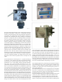
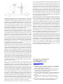
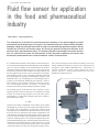
Process automation
Fluid flow sensor for application
in the food and pharmaceutical
industry
Dezső Dányi - Dányi Engineering
The development of the fluid flow measuring devices operating on the electromagnetic principle
was started several decades ago in Hungary, in the manufacturing unit of Gamma Works situated in
Budapest. Initially the production was made as a part of a manufacturing agreement together with the
German firm Krohne for the German export, but shortly the product has become dominant at the
domestic water- and wastewater plants. The present publication reports about the market introduction of a small fluid flow sensor, the development of which has been enabled by the research and
development works based on the “Gamma traditions” made in Gamma Works.
It is a fundamental requirement of the production of the measuring sensors in the field of the industry that the manufacturing rooks enabling the
end review and the calibration of the manufacturing tools should be
available The fluid flow measuring devices are in this respect special,
since there are in general no ready available tools for their calibration, but
the development of the product involves generally the development
of the calibrating device as well. This applies in particular to the fluid
flow measuring devices operating on electromagnetic principle [1]. The
manufacturer has to use a calibrating device corresponding to the prescriptions of an international standard (the ISO 9104:1991 “Measurement of fluid flow in dosed conduits - Methods of evaluating the performance of electromagnetic flowmeters for liquids”) in order that the
document issued for the product should be accepted as credible.
The construction design and the method of building in have been
already standardised within the European Union, and therefore the
prescription of the standard MSZENISO 6817, “Measurement of
conductive liquid flow in closed conduits. Method using electromagnetic flowmeters” should be kept both from the side of the
manufacturer and that of the user.
The operating principle of the fluid flow sensor operated on electromagnetic principle is based on the kinetic law of induction, according
to which, if a conduct having a length of L is moved with a speed v,
perpendicularly to a homogeneous magnetic field with a constant induction B, then the voltage
u = BLv
induced in the conduct is independent on the resistance of the conduct
and depends only on the velocity of the conduct. In the induction sensors
the conduct will be substituted by the electrically conductive fluid
flowing between the insulated electrodes built in the tube wall. In reality
this can be, however, realised only with countless compensations. One
of the problems can be that the constant magnetic field can polarise the
ions to be found in the fluid, which, deposited on the electrodes, can
produce an insulating surface. To avoid this, the magnetic field will be
generated with alternating pulses. The other problem is that the velocity
of the fluid is not alike in the whole cross section of the tube, it is equal
to zero at the wall of the tube and at the other points it will depend
on the shape and the size of the previous and following tube section.
Figure 1
Figure 3
Figure 2
Since the operation of the fluid flow sensor operating in the principle of
the inductive measurement – within limits – is independent on the fluid
properties, makes the utilisation of the sensor particularly advantageous
in the fields of the pharmaceutical and food industries. Namely, the
measuring tube of the fluid flow sensor operating on the induction
principle is a straight tube made of insulating material, with smooth
wall, not containing protruding elements and this circumstance makes
the cleaning of the tube very easy and makes it suitable for the measurement of materials containing solid particles, pulpy, concentrated
acid or alkali substances. Its disadvantage is however that it cannot be
used for the measurement of insulating fluids, e.g. oil, gasoline. This
disadvantage has been reduced, however, with the development of the
electronics and the present designs are suitable for example for the
measurement of the boiler feed water having only some (µS/cm) conductivity as well. A further disadvantage is that in the case of installing the sensor great attention should be paid to grounding of the
fluid flow sensor, since the induced voltage serving for the measurement has mV order of magnitude and if the insulation resistance
of the pump assuring the flow of the fluid is not high enough, then –
in the case of improper grounding – the leakage current will be closed
through the sensor toward the ground and this will tamper the test
signal.
The miniature fluid flow measuring devices – in general measuring up
to 100 L/min – form a separate group of the electromagnetic fluid flow
sensors that are to be used in built-in state as part of a device. Their
manufacturers, the so called OEM (Original Equipment Manufacturer) users put up special demand concerning the easy interchangeability and therefore the pipe connections of the devices to be
built in are therefore standardised. The SENSOFLO™ fluid flow
sensor product family developed by us applies Clamp pipe fittings – that
are widely used in the pharmaceutical and food industries according to
the DIN 32676 and ISO 2852 standards – as part of the measuring tube,
which means that the measuring tube and the pipe fitting form one unit
during the calibration (Figure 1). The same principle is also applied for
the widespread plastic tubes with the difference that there the pipe fittings Adaptor Union widely spread by the Swiss Georg Fischer firm will
be built in before the calibration (Figure 2). It is a great advantage of this
solution that the pipe fittings can perform the task of the grounding of the
of the fluid simultaneously as well, since the metallic parts of the pipe
fittings to be found on the two sides of the measuring tube have been
Figure 4
electrically connected to each other in the factory and thereby the circuit
of the pump leakage current cannot be closed through the measuring
tube. The diameter nominal DN25 and DN40 stainless steel tubes, as
well as the stainless steel tubes with nominal diameter of 1” and 1.5”
use the same Clamp pipe fitting with a diameter of 50.5 mm, which are
generally applied in the American and Far East markets. This is very
advantageous at the development of the calibrating device, since the
DIN standard used in the European Union specifies the inner diameter
of the pipe, while the ISO standard widely used in the USA specifies the
outer diameter of the pipe. Thereby the scope of utilisation of the fluid
flow sensors calibrated with the Clamp fitting is very wide.
The widespread application is promoted by the fact that the electronics
of the SENSOFLO™ has a variety of output signals (adjustable pulse
value of 1, 10, 100 or 1000/liter, transmitter output of 4...20 mA, as well
as RS485.) The output signal of the switch having three positions enables a special application.
The output signal of the pulse value is a signal generally used, if the fluid
flow sensor is connected with a PLC Programmable Logic Controller)
The digital output signal according to the standard RS486 can be used, if
the fluid flow sensor is connected to a computer network.
Namely the MODBUS RTU-protocol applied to the digital output signal
is free to user, and so it stands before a wide spread, similarly to the
widespread analogous 4...20 mA DC signal [2], [3]. The above mentioned output signals are routed to connectors on the rear of the sensor
(Figure 2). The speciality of the device is the output switch having three
Figure 5
positions bled through the power cord. This switch will switch at an
adjustable fluid quantity or fluid velocity and by means of it an actuator
(electromotor or electropneumatic transformer) can be operated. This
will namely allow that the SENSOFLO™ fluid flow sensor can be applied for metering and fluid flow adjusting task, too. The design of the
backsheet can facilitate the assembly of the device to a great extent. The
“LED” labelled red indicates that there is power, the “LED” labelled
green indicates that fluid flow exists. The QR code with “FLOW” label
decoded with a smartphone the User Manual can be read.
An important way of application of the fluid flow sensors is the measurement of the flow rate. Therefore the electronics design is such that
only one way flow will be detected; therefore it is of great importance at
the installation of the device that the flow direction be the same as the
direction of the arrow to be found on the side of the device. At such
applications it is an important aspect that the feed cannot be switched
off, since each switching on operation some time is necessary for the
revival of the electrodes that can tamper the measurement result. The
measurement result can be also tampered by the flow of fluid leakage
during stoppages. This failure will be eliminated by the SENSOFLO™
fluid flow sensor so that in the lower 1…5% of the measurement range
to be adjusted the flow rate will not be measured.
At applications in the pharmaceutical industry, it is an essential aspect
that the fluid flow sensor be explosion proof. If the fluid measured is not
explosive in itself, the device may still be in the vicinity of pipelines
containing flammable substances that, in case of failure, raise the risk of
explosion. Each electromagnetic sensing electronic device contains a
magnetic circuit having significant inductance, which cannot be made
spark ignition free. This problem is resolved in the SENSOFLO™ fluid
flow sensor so that the part containing the electronic power supply and
the coil is cast out of plastic resin and therefore in the case of a failure in
the hazardous area no sparks can create ignition. The utilisation in an
explosion dangerous area the usability demands the solution, where the
feeding and the circuit of the switching circuit having higher current
intensity as 100 mA are not connected through the connector, but should
be connected with a cable, galvanically isolated from the inner electronic device with the sensor.
In the case of a dosing application the switch circuit of the
SENSOFLO™ will open a valve so long as the set amount of fluid will
flow through and the valve will be closed. The fluid flow display unit
SENSOFLO™ can be put to the connector labelled “DISPLAY” to be
found on the backboard of the device (Figure 3), and on the front cover
of this the quantity read to be charged can be adjusted and the actual
flow rate can be read. In the application in the field of the food and
pharmaceutical industries the assembly of the SENSOFLO™ fluid flow
sensor with the actual quantity can be read. At the applications in the
Food industry and in the Pharmaceutical industry the assembling with
the Painter valve VZQA is particularly advantageous, since this valve
has the same diameter as that of the measurement tube of the sensor.
where the quantity of the amount of liquid flowing through can be adjusted by the compressing of the tube wall using air (Figure 4). Thereby
the valve will be a part of the measurement tube and can be calibrated
together with it and will correspond to all cleaning requirements,
The flowing characteristics of the valves applied for setting purposes
will be in general influenced by the practical geometric design of the
valve seat/valve body group [4] [5], The movement of such valves is
assured with an electromotor or pneumatically with a feedback to the
place of the valve-stem, using the so called positioning device. The
disadvantage of this solution is that the set pattern is only fulfilled, if a
pressure drop of 1 bar will be realised. The valve characteristic can be
made independent using a solution being under patent application from
the pressure drop to be found at the valve, if the valve will be assembled
with the SENSOFLO™ fluid flow sensor and the flowing through fluid
flow will be fed back to the governing signal. The so developed fluid
flow adjuster has the great advantage that the special design of the valve
seat/valve body group is not necessary.
The technologies used in the chemical industry requiring stirring commonly use not the continuously, but suddenly will be called out with a
ration, acting “batch processing” technology. The essence of this is that
– under regulated temperature and pressure ratios – during continuous
mechanic stirring another substance will be added to the liquid-phase
raw material and as a result of this operation after the reaction time another product will be created. In the food industry, for the most part, it is
unnecessary to split the process in portions in the case of creating a new
product; it is much more appropriate to use of continuous rather than
intermittent technology, where the stirring will be performed using a
static stirring device. For the adjustment of the static stirring devices, the
SENSOFLO™ fluid flow sensor assembled with valve shown in the
Figure 4 is particularly appropriately used, since its flowing characteristic is independent on the pressure drop occurring at the valve.
Figure 5 shows the utilisation of the SENSOFLO™ fluid flow sensor for
the adjustment of the stirring devices. The technological task is the
creation of the product C with the mixing of the products A and B. The
flowing quantity of the fluid transported by the pump 1 will be measured
by the fluid flow sensor 2 and the measurement signal will be added to
the adjusting device 3. The SENSOFLO™ fluid flow sensor assembled
with the valve 4 measures the flowing quantity of the fluid B and
transmits it to the adjusting device, which adjusts the valve 5 so that the
ratio of the fluid flows A and B be the prescribed value in front of the
static mixer independent on the pressure drop.
Dányi Engineering - DE Flowmeters Kft.
1141 Budapest, Cserebogár utca 39.
Tel.: +36 1 469 0485
E-mail: [email protected]
www.danyi-engineering.hu
LITERATURE
[1] György Léb, Dr. László Szilassy: Ami egy 0,1%-os áramlásmérő-hitelesítő mögött van [Principles behind a 0.1% calibrating
device]. Magyar Elektronika, 2014/1-2
[2] Ferenc Pástyán: Áram-és teljesítménymérők RS485 interfésszel
[Current and performance measuring devices using RS485
interface]. Magyar Elektronika, 2014/10
[3] Com-Forth Ltd: Kísérletezés helyett – intelligens RS485 [Instead
of experimenting – intelligent RS485]. Magyar Elektronika
2014/5
[4] Dezső Dányi, Dr. Zoltán Telkes: Szabályozó berendezések
[Control devices], College textbook. Tankönyvkiadó, Budapest,
1981
[5] Péter Mizsey: Folyamatirányítási rendszerek [Process control
systems], College textbook. TYPOTEX Budapest 2011.