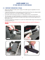
1
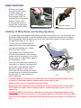
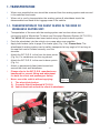
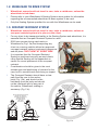
®
(Complex Care Wheelbase)
USER’S MANUAL
ALL USER’S OF THE EQUIPMENT SHOULD BE AWARE
OF THIS DOCUMENT AND ITS CONTENT
| CLASS 1 DEVICE
ISSUE 1
Index
CONTENTS
PAGE
Index
Introduction Serial No
Brake Variations
Stability of Wheelchair and Seating Systems
Recommendations on Transport
Safety Guidelines for Transportation
Transportation
WTORS Manufacturers
Key Identification Points
1
2
2
3
3
4
5
6-8
8
9 & 10
1.0
User’s Guide “Preparing Wheelbase For Use”
1.1
1.2
1.3
1.4
1.5
1.6
1.7
Unfolding the Handles
Folding the Handles
Attaching & Releasing the Seat
Tilt Operation (When Fitted)
Handle Height Adjustment
Attendant Parking Brakes (When Fitted)
Storage Tray
2.0
User’s Guide “Fitting & Use of Accessories”
2.1
2.2
2.3
2.4
2.5
Footrest Adjustment (If Fitted)
Swing Aside Footrest Adjustment (If Fitted)
Armrest Adjustment (If Fitted)
Sunshade/Rain Canopy Fitting & Removal (If Supplied)
Solo Rain Canopy Fitting & Removal (If Supplied)
3.0
User’s Guide “Placing the Client”
3.1
3.2
Seating the Client When Using the Wheelbase
Removing the Client from the Seating System
4.0
User’s Guide “Manoeuvring The Wheelchair”
4.1
Pushing the Wheelchair
5.0
User’s Guide “Looking After The Wheelbase”
5.1
5.2
Cleaning
Fault Finding
24
24
5.3
Maintenance
25
If You Detect a Fault or Breakage
CONTACT DETAILS
1
11
12
13
14
14
15
15
16
17
18
19 & 20
21
22
22
23
26
Backpage
MOJO CC WHEELBASE
Introduction
•
•
•
•
•
•
•
(Class 1 Device)
This Users Guide for the Wheelbase is designed to give guidance on its use and
maintenance.
The Wheelbase is designed to use a SOS interface system when using special
seating systems.
To make sure that placing a seating system in the wheelbase does not render it
unstable, it is recommended that when handing the MoJo CC and seating system
over to the client it is tested for stability and a Certificate of Compliance is issued to
verify that the level of stability is satisfactory (for more details regarding stability of
wheelchair & seating systems, see page 3).
When used in transport the whole system MUST be securely fastened to the floor of
the vehicle (WHEELCHAIR TIE DOWNS) and the vehicles safety belts (OCCUPANT
RESTRAINT) MUST be used in conjunction with the seating systems straps. (See
Guidelines for Transportation on pages 4 - 8)
The wheelbase has been tested to and conforms to the transport requirements as
specified in ISO 7176-19:2001.
The maintenance and safety instructions described in the manual must be adhered to.
By following these instructions you will be ensuring correct use of the Wheelbase and
its safety in use.
It is also important to read the ‘Seating System User Manual’ with regard to general
use, transportation use and maintenance.
Serial No.
• Each Wheelbase has a unique Serial Number Plate attached to the base frame for
identification. A copy of the Unique Serial Number is attached below for reference:
2
BRAKE VARIATIONS
• Reference is made
through out this Users
Guide to apply the
brakes, the images on
those pages show the
standard Hand Operated
brakes. Please refer
to the figures below to
identify the correct type
of braking system fitted.
Standard
Attendant Parking
Stability of Wheelbase and Seating Systems
• To ensure that the Wheelbase and Seating System are safe to use, it is important that
•
•
•
•
•
•
•
fitting the Seating System to the Wheelbase does not make the wheelchair unstable.
Each Wheelbase when handed over to the user should be tested for static stability to
the specified angle of 12° (Fig.1).
It is also recommended that any
additional items to be used with the
seat and wheelbase are in place
when the test is done.
The stability test is always done
with the client seated in the seating
system and all equipment to be used
by the client on a daily basis when in
the wheelchair in situ.
Once the test has been successfully
completed, a Stability Certificate will
be issued by Specialised Orthotic
Services Limited. A copy of this
certificate will be handed over when
the equipment is supplied and should
be kept with the user manual for
future reference.
12°
Fig.1
The Wheelbase is not to be used with any other Seating System(s) than those
for which it has been stability tested and proven safe for use.
Always steer clear of obstacles where possible.
When using the equipment never attempt to climb or descend an incline where
the surface is rough, wet or slippery (gravel, loose chippings, grass, rain, ice,
snow, etc).
WARNING: Whilst the client is seated in the wheelchair, the attachment of any
heavy object to the wheelchair (i.e. shopping bags etc.) will have a serious effect
on the overall stability of the wheelchair and may place the safety of the client at
risk.
3
Recommendations for the
Transportation of SOS Wheelbases & Seating Systems
The following information is intended to give guidance with regard to the use
of SOS Wheelbase & Seating Systems by wheelchair users and carers during
transportation.
•
•
•
Specialised Orthotic Services Ltd have carried out extensive investigations into the
suitability of our Wheelbases & Special Seating Systems for transportation use and
has established clear guidelines for users.
Following these investigations the following user information is intended to give
guidance to users of SOS Wheelbases & Seating Systems regarding the use of the
equipment during transportation.
As part of the assessment process, transportation requirements will be assessed.
This information will be of interest to all parties involved in the daily management of
the wheelchair user (Relatives, Carers, Support Staff, Healthcare Professionals and
Transport Service Providers).
4
General Safety Guidelines for
Wheelchair User Transportation
•
•
•
•
•
•
•
•
All Wheelchair users should transfer to vehicle seats whenever possible.
The Wheelchair is designed to be forward facing when used for transportation of the
client in an adapted motor vehicle and users should not travel with the wheelchair at
an angle or facing sideways to the direction of travel.
There should be sufficient free space around the wheelchair and user to avoid the
user making contact with other vehicle occupants, unpadded parts of the vehicle,
wheelchair accessories or W.T.O.R.S. anchor points.
It is important to apply brakes during transport.
Mobility equipment should not block gangways and exits for other passengers in the
vehicle.
A headrest should be provided for use when travelling in a vehicle where other seated
passengers have headrests.
Do not place / hang any additional items onto the wheelchair during transportation
such as shopping bags and holdalls.
Trays (excluding under tray) should be removed for transportation and secured
separately in the vehicle or be secured to the wheelchair but positioned away from the
occupant with energy-absorbing padding placed between the tray and the occupant.
Wheelchair Tie Down and Occupant Restraint System
(W.T.O.R.S.)
•
•
Secure methods for the safe retention of wheelchairs have been developed and are
used on a regular basis to secure wheelchairs during transportation use.
These systems are now commonly referred to as W.T.O.R.S.
Wheelchair Tie down and Occupant Restraint Systems
•
•
There are many types of W.T.O.R.S. available from various manufacturers, (a list of
some manufacturers is given on page 8). Refer to your Seating System Manufacturers
Handbook for details of their particular recommendations.
Please note that all lap /chest belts and harnesses supplied with the seating system
are not sufficient for occupant restraint when the equipment is used on a moving
vehicle and additional Occupant Restraint is required.
5
1. TRANSPORTATION
•
•
When ever possible the user should be removed from the seating system and secured
in the vehicles fixed seats.
When not in use for transportation the seating system & wheelbase should be
disassembled and fixed in the luggage area of the vehicle.
1.1. TRANSPORTATION OF THE CLIENT SEATED IN THE MOJO CC
WHEELBASE SEATING UNIT.
• Transportation of the user with the seating system can be done when used in
•
•
•
•
•
•
•
conjunction with a Wheelchair Tie down and Occupant Restraint System (W.T.O.R.S.).
The MOJO CC wheelbase has been tested using a 4-point tie down system.
Push the wheelchair into the vehicle via a ramp when ever possible.
Apply both brakes (refer to page 3 for brake type) (Fig.1.1a). Please Note: The
wheelbase & seating system can be safely transported at any angle of tilt as long as
the seat belt can be located correctly over the
shoulder.
Attach the W.T.O.R.S. to the front tie down points
(Fig.1b). For carabiners use the ring shown.
Attach the W.T.O.R.S. to the rear tie down points
(Fig.1c).
Attach a permanently fixed vehicle seat belt
around the client and wheelbase.
Please refer to the W.T.O.R.S. manufacturers
handbook for correct fitting and adjustment
for both the client and passengers safety.
Never move the vehicle without applying:
Fig.1.1a
i) The wheelchair brakes.
ii) Correctly fitted & adjusted W.T.O.R.S.
iii) Vehicle seat belt around the client & wheelbase.
Fig.1.1b
Carabiner
Ring
Fig.1.1c
6
1.2. WHEELCHAIR TIE DOWN SYSTEM
• Wheelchair users should not travel in cars, taxis or minibuses, unless the
•
•
wheelchair is tied down.
Please refer to your Wheelbase & Seating System users guides for information
regarding the recommended wheelchair tie down system to be used.
Only the Seating System specified for use with the Wheelbase can be used.
1.3. OCCUPANT RESTRAINT SYSTEM
• Wheelchair users should not travel in cars, taxis or minibuses, unless an
•
•
•
•
•
occupant restraint system is in place on the client.
For any client to be transported safely in the Seating System and wheelchair, it is
essential that an Occupant Restraint System be used.
SOS have proven during crash tests on
Wheelbase’s (Fig.1.3a) that transporting any
client on a moving vehicle without an approved
occupant restraint system is extremely dangerous
and will place the client at great risk.
It is important that the Occupant Restraint
System is positioned correctly as most clients
using Special Seating will be dependent on
carers for correct placement of the occupant
restraint.
Consideration should be given to the most
suitable type and positioning of restraint for the
user, both in normal travel and during an impact.
The Occupant Restraint should have a clear
path from the user to the anchor
point (Fig.1.3b), and should not be
held away from the body and should
not be interfered with by any part of
the vehicle, Wheelbase, seating or
accessory (Fig.1.3c).
Fig.1.3a
RESTRAINTS SHOULD
NOT BE HELD AWAY FROM
BODY BY WHEELCHAIR
COMPONENTS SUCH
AS ARMRESTS
OR WHEELS
PELVIC RESTRAINTS SHOULD
MAKE FULL CONTACT
ACROSS THE FRONT OF
THE BODY NEAR
THE JUNCTION OF
THE THIGH
AND PELVIS
Fig.1.3b
Fig.1.3c
7
1.4. STOWAGE OF THE WHEELBASE AND SEATING SYSTEM
• During use of your Special Seating System it may be necessary for you to remove the
•
•
•
Seating System and stow this along with the Wheelbase in a vehicle.
It is important to realise that these items pose a risk if not adequately restrained
whilst in transit.
It is not adequate to simply place the items into a car boot or the floor of an open
vehicle such as an MPV or estate car as in a collision these unsecured items could
cause serious injury to occupants of the vehicle.
Various retention methods are available to secure such equipment during transit, and
once again the list of Wheelchair Restraint System Manufacturers in this booklet will
be happy to advise on this matter (see below).
W.T.O.R.S MANUFACTURERS
Below are details of some Wheelchair Tie down and Occupant Restraint Systems
manufacturers.
UNWIN SAFETY
SYSTEMS
Unwin House
The Horseshoe
Coat Road
Martock
Somerset
TA12 6EY
TEL: 01935 827740
FAX: 01935 827760
E Mail: [email protected]
KOLLER
ENGINEERING LTD
Unit 5, Garrett Road
Lynx Trading Estate
Yeovil
Somerset
BA20 2TJ
TEL: 01935 426695
FAX: 01935 433766
E MaiI: [email protected]
QSTRAINT
(EUROPE)
72 - 76
John Wilson Business Park
Whitstable
Kent
CT5 3QT
TEL: 01227 773035
FAX: 01227 770035
E MaiI: [email protected]
8
2. KEY IDENTIFICATION POINTS
2.1. STANDARD
• SOS MOJO CC Wheelbases are provided either with a fixed or tilting frame (Fig.2.1)
and a seating system quick release interface (Fig.2.2 on page 10).
1
8
7
10
9
2
6
5
11
4
12
3
Fig.2.1 Tilting Frame
1.
2.
3.
4.
5.
6.
Push Handles
Tilt Base
Wheelbase
Hand brake
Front Tie Down Point
Rear Tie Down Point
7. Handle Adjustment Knob
8. Tilt Lever (Hand operated)
9. Handle Locking Catch
10. Interface Location (see page 10)
11. Rear Foot Lever
12. Storage Tray
9
2. KEY IDENTIFICATION POINTS (Cont.)
2.2. SEATING SYSTEM INTERFACE
1
5
3
3
4
2
2
Fig.2.2
1. Frame
2. Front Location (x2)
3. Rear Catch (x2)
4. Release Cable
5. Offset Spigot
Assembly (x4)
2.3. THE SEATING SYSTEM
• Seating Systems need to be interfaced to the Wheelbase safely and it is important
•
•
that the interface system supplied with the Wheelbase is used in conjunction with any
retention straps supplied with your seating system.
It is recommended that seating systems are attached to the MoJo CC Wheelbase
using an SOS “MoJo Wheelbase Seat Interface”. (see tech spec for reference and
interface product codes)
Please refer to any handbooks supplied with your seating system before attaching it to
the Wheelbase.
10
USER GUIDE 1.0
PREPARING THE WHEELBASE FOR USE
1.1. UNFOLDING THE HANDLES
• Make sure that both brakes (refer to page 3 for brake type) are applied to the rear
•
•
wheels (Fig.1.1a).
Pull handle upwards until it is up against the stops (Fig.1.1b).
Slide the handle locking catch over the base upright until it reaches the stops
(Fig.1.1c), the locking pins will automatically pop into place.
Fig.1.1a
Fig.1.1b
Fig.1.1c
11
1.2. FOLDING THE HANDLES
• Make sure that both brakes (refer to page 3 for brake type) are applied to the rear
•
•
wheels (Fig.1.2a).
Push in locking pin and slide the handle locking catch up & clear or the base uprights
(Fig.1.2b).
Push handle down and let it rest on the base frame.
Fig.1.2a
Fig.1.2b
12
1.3. ATTACHING THE SEAT
• Make sure that both brakes (refer to page
•
•
•
3 for brake type) are applied to the rear
wheels (Fig.1.3a).
Locate the front of the interface frame
into stops as shown (Fig.1.3b).
Lower the interface into the rear catches
as shown until it clicks into position
(Fig.1.3c).
Please refer to handbooks supplied
with your seating system for any
additional security devices (i.e.
Retaining Straps) that need to be fitted
prior to client use.
Fig.1.3b
Fig.1.3a
Fig.1.3c
RELEASING THE SEAT
• Make sure that both brakes (refer to page
•
•
Fig.1.3d
•
13
3 for brake type) are applied to the rear
wheels (Fig.1.3a).
SOS recommends that the client is
always removed from the seating system
before releasing the interface and
removing seats. Never try to lift the
client in the seat system
To release the seat pull back the interface
cable (Fig.1.3d) until the catches release,
raise up the rear of the interface clear of
the catches, release the lever and pull
the interface clear of the front stops.
Now lift the seat and remove.
1.4. TILT OPERATION (when fitted)
• Make sure that both brakes (refer to page 3 for brake type) are applied to the rear
•
•
wheels (Fig.1.4a).
Make sure seating system and user are in place.
Squeeze the tilt lever (Fig.1.4b) and apply your weight to the push handles until
desired angle of tilt is achieved then release the lever. To raise the seat just squeeze
the lever until tilt required and release.
Fig.1.4a
Fig.1.4b
1.5. HANDLE HEIGHT ADJUSTMENT (when fitted)
• Release knobs and lift (or lower) handle to its desired position (Fig.1.5a).
• When in position re-tighten the knobs (Fig.1.5b).
Fig.1.5a
Fig.1.5b
14
1.6. ATTENDANT BRAKES (when fitted)
• To put the brakes on, Squeeze both brake levers (Fig.1.6a) until the brakes are
•
•
securely on then let go of the lever as this will stay in place.
To release the brakes, Squeeze both locking levers under the brake levers (Fig.1.6b)
and allow the brake levers to return to the off position, then let go of the locking levers.
Never let go of the wheelchair unless both wheel brakes are applied.
Fig.1.6a
Fig.1.6b
1.7. STORAGE TRAY
• To extend the tray: Release the knob at the rear of the tray (Fig.1.7a), let the wheels
•
•
•
•
down until touching the floor and then tighten the knob.
Press the release button at the front of the tray (Fig.1.7b), firmly push the tray out to
release the catches under the tray until tray comes up against it’s stops.
To retract the tray: Push the tray back under the chassis until the catches underneath
the tray and the release pin at the front engage.
Release the knob at the rear of the tray (Fig.1.7a), raise up the wheels and tighten the
knob. DO NOT push the wheelchair with the wheels lowered.
Any equipent stored in tray MUST be securely tied down during transport.
Fig.1.7a
Fig.1.7b
15
USER GUIDE 2.0
FITTING AND USE OF ACCESSORIES
2.1. FOOTREST OPERATION (if fitted)
• Make sure that both brakes (refer to page 3 for brake type) are applied to the rear
•
•
•
•
•
wheels (Fig.2.1a).
Locate the footrest stem in the mounting socket (Fig.2.1b), Press the release button
and slide footrest fully in until catch engages, release button.
Foot plates can be swung up (Fig.2.1c) to help gain access to the wheelchair.
The foot plates are height adjustable by releasing the nut and bolt at the rear of the
stem (Fig.2.1d) and moving the foot plate up the stem to the desired height then retightening the nut.
To remove footrests for transport, etc, press the release button (Fig.2.1b) and pull the
footrest assembly out.
DO NOT at any time stand on the foot plates as this can result in damage or
injury.
Fig.2.1a
Fig.2.1b
Fig.2.1c
Fig.2.1d
16
2.2. SWING ASIDE FOOTREST OPERATION (if fitted)
• Make sure that both brakes (refer to page 3
•
•
•
•
•
for brake type) are applied to the rear wheels
(Fig.2.2a).
Hook the footrest assembly on to the location
pegs (Fig.2.2b), swing the footrest fully inboard
until the catch engages.
Foot plates can be swung up (Fig.2.2c) and by
pressing the release lever (Fig.2.2d) swung aside
to help gain access to the wheelchair.
The foot plates are height adjustable by releasing
the bolt at the side of the stem (Fig.2.2e) and
moving the foot plate up the stem to the desired
height then re-tightening the nut.
Fig.2.2a
To remove footrests for transport, etc, press the release lever (Fig.2.2d), swing the
footrest to the side and lift the footrest assembly off the location pegs.
DO NOT at any time stand on the foot plates as this can result in damage or
injury.
Fig.2.2b
Fig.2.2c
Fig.2.2d
Fig.2.2e
17
2.3. ARMREST OPERATION (if fitted)
• Make sure that both brakes (refer to page 3 for
•
•
•
•
•
brake type) are applied to the rear wheels (Fig.2.3a).
Locate the armrest stem in the mounting socket
(Fig.2.3b), set the armrest at the required height
and tighten the knob (Fig.2.3c). Please note: the
armrests can be fitted and used in the forward or
reverse position.
Slide the locking collar down on to the socket
(Fig.2.3d) and tighten the grub screw (this allows the
height to be retained when replacing armrest after
removal).
Fig.2.3a
Armrests can be moved in-board or out-board by releasing the screw & lock nut on the
upper frame and sliding in or out to the required position, re-tighten screw & lock nut
when finished (Fig.2.3e).
To remove armrests for transport, etc, release the knob on the socket and lift out. If at
any time you require the height to be altered you must release the grub screw on the
locking collar.
DO NOT at any time lift the wheelbase via the armrests as this can result in
damage or injury.
Fig.2.3b
Fig.2.3c
Fig.2.3d
Fig.2.3e
18
2.4. SUNSHADE/RAIN CANOPY FITTING (if supplied)
Fitting Sunshade:
••
Locate the frame legs into the frame receivers (Fig.2.4a), set to height required and
tighten in place with wing knob.
••
Push the centre of the frame locking bar until straight so that the sunshade is
tensioned properly (Fig.2.4b). Repeat for other side.
••
Correctly fitted & tensioned sunshade as shown (Fig.2.4c)
••
Removal is a reversal of the above.
Fig.2.4a
Fig.2.4b
Fig.2.4c
19
2.4. SUNSHADE/RAIN CANOPY FITTING (if supplied) Cont.
Fitting Rain Canopy:
••
Remove the rain canopy from the zipped pouch on the back of the sunshade
(Fig.2.4d).
••
Unfold the rain canopy and hook over the sunshade as shown (Fig.2.4e).
••
Pull the rear panel down between the MoJo handles and hook the front of the rain
canopy around the footbox on the seating system (if fitted).
••
Hook the two elasticated straps around the rear tie down hooks as shown (Fig.2.4f).
Repeat for other side.
••
Correctly fitted rain canopy as shown (Fig.2.4g)
••
Removal is a reversal of the above.
•
Please ensure the top & bottom retaining straps (Fig.2.4f) are released BEFORE
folding/removing to prevent damage to the rain canopy.
Fig.2.4d
Fig.2.4e
Fig.2.ff
Fig.2.4g
20
2.5. SOLO RAIN CANOPY FITTING (if supplied)
••
Fix the two frame clips on to the handle frame either side of the tilt handle (Fig.2.5a).
Repeat for other side.
••
Unfold the rain canopy and fix the two halves of
the Velcro straps (at top & bottom) between the
two clear panels (Fig.2.5b). Repeat for other side.
••
Correctly fitted rain canopy as shown (Fig.2.5c)
••
Removal is a reversal of the above.
Fig.2.5a
Fig.2.5b
Fig.2.5c
21
USER GUIDE 3.0
PLACING THE CLIENT
3.1. PLACING CLIENT INTO SEATING IN WHEELCHAIR
• Apply both wheel brakes (refer to page 3 for brake type).
• Set tilt (if fitted) in the required position.
• Make sure all client retaining straps are outside of seating system this will avoid the
•
•
•
•
•
•
client sitting on them when placed in the seat.
Hinge the footplates (if fitted) out of the way. DO NOT stand on the footplates.
Lower the client into the wheelchair using a hoist (Please refer to your hoist ”operators
manual”).
Manually lifting the client is not recommended.
With some clients it may not be possible to hoist them safely by conventional
means and in instances such as this you are recommended to carry out a ‘RISK
ASSESSMENT’ to assess the risks involved in any such action. (It is important that
all carers are aware of the Health & Safety guidelines for ‘Lifting and Handling’).
Lower the footplates (if fitted) & place feet on them.
Secure all straps/harness (if fitted) & tighten if necessary (Please refer to your
“special seating users manual”).
3.2. REMOVING THE CLIENT FROM SEAT IN WHEELCHAIR
• Apply both wheel brakes (refer to page 3 for brake type).
• Set tilt (if fitted) in the upright position.
• Remove all straps/harness (if fitted) & place outside of seating system (Please refer to
•
•
your “special seating users manual”).
Hinge the footplates (if fitted) out of the way. DO NOT stand on the footplates.
Using a hoist lift the client from the seating system (for manual lifting please refer to
section 3.1).
22
USER GUIDE 4.0
Manoeuvring the wheelchair
4.1. PUSHING THE WHEELCHAIR
• Apply both wheel brakes (refer to page 3 for brake type) & make sure client is
•
•
•
•
•
•
•
•
•
•
•
•
•
•
comfortable/securely seated in the wheelchair (see user guide 3.0).
Set tilt (if fitted) to suit the clients needs & adjust
handle height.
Release both wheel brakes (refer to page 3 for
brake type) Note: always apply both wheel
brakes when stationary for long periods of
time.
Push the wheelchair by using both hands on the
handles provided to prevent instability and erratic
steering.
To tilt the wheelchair back (for going up kerbs,
etc.), lower the foot pedal at the rear of the
wheelchair (Fig.4.1a) and press down with the
foot (Fig.4.1b).
Fig.4.1a
Never let go of the wheelchair unless both
wheel brakes are applied.
Always look well ahead to avoid any hazards
and to prevent any sudden directional
changes.
Never push the wheelchair above walking
pace or turn suddenly to prevent distressing
the client or causing harm to passers by.
Never allow anything to hang near or on the
wheels (i.e. Clothing, clients equipment, etc.).
Never hang anything on the back of the
wheelchair (i.e. Bags, coats, etc.) as this
could cause instability during use.
Fig.4.1b
The wheelchair should only be used by the
client it was supplied for and NO other person.
Always use both hands and foot lever (Fig.4.1b) when tilting the wheelchair.
Never tilt the wheelchair too far back as to make it unstable.
Never approach the kerb at an angle, always approach straight to prevent one
side lowering before the other causing sideways instability.
If possible always place the wheelchair in the reverse position to drop down a
kerb.
23
USER GUIDE 5.0
LOOKING AFTER the wheelchair
5.1. CLEANING
• Clean the frame with a damp cloth.
• To clean the wheels use warm soapy water.
5.2 FAULT FINDING CHECKS
• This fault finding chart offers possible causes and remedies that can occur over time
depending upon usage. For adjustment and repairs, contact your wheelchair service.
Symptoms
Pulls or
veers to
the side
Slow
Turning
P
P
P
P
Castor
Wobble
Squeaks
&
Rattles
play in
seating
system
Checks/Causes
Make sure tyre pressure is correct and
equal in both pneumatic tyres
P
P
P
P
P
Check castors for wear and for free running
P
Make sure both front castors touch the
ground simultaneously
P
P
P
24
Make sure all nuts and bolts are tight
Make sure seating interface is located
properly and working
5.3. MAINTENANCE
• Your MoJo CC Wheelbase is designed to require the minimum amount of
•
•
maintenance, which should only be carried out (along with any repairs) by an
authorized repairer.
We recommend that, at least once a year, your wheelchair service carry out a
thorough inspection and service of your wheelbase.
We recommend that users should check their wheelbase regularly to the schedules as
shown below:-
Interval
Component(s)
Checks To Be Made
General
The wheelchair moves in a straight line (no resistance
or drag)
Brakes
They are securely attached, properly adjusted and
operating correctly.
Front Castors
That they are free to rotate, and that the castors swivel
freely and are not damaged.
Solid Tyres
The running surface (tread) for wear or damage
pneumatic tyres
That they are correctly inflated (the pressure is shown
on the side wall) and for wear or damage
Seating System
Interface is working properly and retaining seat in place
correctly
General
The wheelbase unfolds and folds easily
Rear Wheels
Wheel nuts correctly tightened
Armrests
Firmly attached but easy to remove
Footrests
Adjusted correctly and securely fitted
Nuts and Bolts
That all nuts and bolts are in position and tightened
Pivot Points
Nylon fittings for wear or damage
Frame
For any signs of wear or damage
Armrests
That the padding is in good condition
Tilt-in-Space
For any signs of wear or damage and that the gas
struts still raise and lower with client in place
Weekly
Monthly
Yearly
25
IF YOU DETECT A FAULT OR BREAKAGE
1. IF YOU DETECT A FAULT OR BREAKAGE OF THE EQUIPMENT THEN REPORT
THIS IMMEDIATELY TO YOUR WHEELCHAIR SERVICE.
2. UNDER NO CIRCUMSTANCES ARE ANY MODIFICATIONS / ALTERATIONS TO
BE DONE BY ANYONE OTHER THAN THOSE AUTHORISED TO DO SO BY THE
WHEELCHAIR SERVICE RESPONSIBLE FOR ISSUE OF THE EQUIPMENT.
3. ANY SUCH UNAUTHORISED ACTION WILL PLACE THE CLIENT AT RISK.
ALWAYS CONTACT YOUR WHEELCHAIR SERVICE WHO WILL THEN
AUTHORISE ANY ACTION NECESSARY TO MAINTAIN OR REPAIR THE MOJO
WHEELBASE.
REPAIRS & SERVICE
Within the warranty period.
All MOJO CC wheelbases manufactured by Specialised Orthotic Services Ltd. carry a
guarantee on the main frames for 60 months and all other parts for 12 months when used
normally. If during this period the product becomes defective and needs repair then please
contact SOS (contact details on the back of the booklet).
You can also contact your local wheelchair service regarding any faults requiring attention.
Outside the warranty period.
For any goods requiring repair or attention after the 12 months period, then assessment
can be made as to the cost of the work required to effect the repair.
On acceptance of this quotation the work will proceed.
Misuse or neglect.
The repairs necessary resulting from misuse or neglect, whether within the warranty
period or not will be charged for.
MEDICAL DEVICES DIRECTIVE 93 / 42 EEC
Specialised Orthotic Services Ltd. in compliance with the Medical Devices Directive
have an obligation to investigate and take corrective action on defective devices. To assist
us with this procedure we would appreciate your assistance in meeting this obligation by
informing us as soon as possible and make the device available for inspection as soon as
possible having become aware of a defect.
We are required to notify the Competent Authority of certain types of incidents within 10 to
30 days.
As part of our quality system we have established procedures to deal with such incidents
and would appreciate your swift notification to us via our telephone, fax or e-mail details at
the end of this users manual.
26
If you require further copies of this handout or require further details relating to any of its
content, then please contact us (Copyright applies):
Units 127/128, Fauld Industrial Park, Tutbury, Staffordshire. DE13 9HS
Tel: 0044 (0)1283 520400 Fax: 0044 (0)1283 520401
E-mail: [email protected]
Web: www.specialisedorthoticservices.co.uk