1
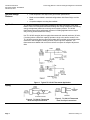
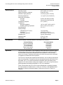
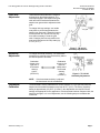
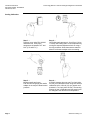
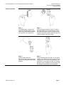
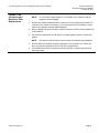
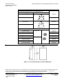
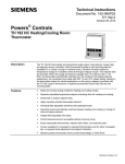
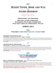
Technical Instructions
Document No. 155-068P25
TH 193-4
October 26, 2010
Powers® Controls
Free Energy Band® TH 193 HC
Heating/Cooling Room Thermostat
50
60
70
80
TH0356R1
70
60
80
POWERS
Description
The TH 193 HC thermostats are proportional dual output, dual setpoint, two-pipe (dual
one-pipe, low air capacity) or three-pipe (dual two-pipe, high air capacity) sensor
controllers. Each thermostat includes a wall mounting plate for installation in a variety of
rough-in terminal boxes. Sensitive bimetals respond to temperature changes to
modulate control air through a flapper nozzle. As the heating load decreases due to
internal heat gains, a dead band of control minimizes energy consumption while the
setpoint changes from 72°F (22°C) heating mode to 78°F (26°C) cooling mode. Two
setpoint dials allow adjustment of the dead band 4°F (2°C) minimum. Air connections
are made with 5/32-inch (4 mm) O.D. plastic tubing, directly to the thermostat chassis
for retrofit applications or with plug-in adapters (provided with the TH 192 rough-in
terminal box or optional accessories), which slide into the wall mounting plate.
Features
•
Direct and reverse acting for heating and cooling modes.
•
Two separate adjustable temperature setpoint indicating dials.
•
Two highly sensitive bimetal thermostatic elements.
•
Fahrenheit or Celsius models.
•
Individual field adjustable sensitivity with graduated scale.
•
Integral field adjustable limit stops.
•
Control pressure test port accessible without removing cover.
•
Easily replaceable thermometer, setpoint dials, filters and restrictor plate.
•
Covers available for concealed or exposed thermometers, and for concealed
adjustment and setpoint indication.
•
Standard plastic thermostat covers provide Desert Beige or white finish.
Siemens Industry, Inc.
Technical Instructions
Document Number 155-068P25
October 26, 2010
Optional Design
Features
Application
Free Energy Band TH 193 HC Heating/Cooling Room Thermostat
•
Fixed temperature limit stops meet government specifications.
•
Metal covers available in standard configurations with Desert Beige or white
finish.
•
Competitor adapter mounting kits available
TH 193 HC thermostats control space temperature and take advantage of the dead
band to "float" room temperature between heating and cooling modes while maintaining
energy management (maximum economy) and occupancy comfort. TH 193 HC
thermostats control valve and damper actuators in building applications that require
early morning heat and afternoon cooling.
Use TH 193 HC two-pipe (dual one-pipe) thermostats with external restrictors (20 scim,
5.4 ml/sec) where a limited air capacity operates a single valve and/or actuator. Use
TH 193 HC three-pipe (dual two-pipe) thermostats where multiple valves and actuators,
used with or without high/low limiting controls, require higher air capacities. The
thermostats are available with covers that conceal or expose the setpoint adjustment
dials.
Figure 1. Typical TH 193 HC Thermostat Application.
Piping
Figure 2. TH 193 HC Thermostat
Dual One-Pipe Connections.
Page 2
Figure 3. TH 193 HC Thermostat
Dual Two-Pipe Connections.
Siemens Industry, Inc.
Free Energy Band TH 193 HC Heating/Cooling Room Thermostat
Product Numbers
and Ordering
Information
Chassis
Technical Instructions
Document Number 155-068P25
October 26, 2010
See Table 1 for product number and ordering information on TH 193 HC thermostat
chassis.
1. Does application require one-pipe or two-pipe connection?
a. One-pipe thermostats are low air capacity devices and have only one port
connection (R1). This application requires an external restrictor.
b. Two-pipe thermostats are high air capacity devices for controlling two or more
terminal devices such as damper actuators or valves. This application requires
two port connections: supply (S) and return (R1).
2. Is a Fahrenheit or Celsius scale required?
3. Is the heating control direct or reverse acting?
4. Is the cooling control direct or reverse acting?
Connection
Type
Table 1. TH 193 HC Thermostat Chassis Part Numbers.
Chassis with Wall Plate
Setpoint
Fahrenheit
Celsius
Adjustment Heating DA Heating RA Heating DA Heating RA
One-Pipe
Relay
Two-Pipe
Relay
Siemens Industry, Inc.
Exposed
at bottom
of cover
Cooling DA
193-211
Cooling DA
193-213
Cooling DA
193-231
Cooling DA
193-233
Cooling RA
193-212
Cooling RA
193-214
Cooling RA
193-232
Cooling RA
193-234
Cooling DA
193-215
Cooling DA
193-217
Cooling DA
193-235
Cooling DA
193-237
Cooling RA
193-216
Cooling RA
193-218
Cooling RA
193-236
Cooling RA
193-238
Page 3
Technical Instructions
Document Number 155-068P25
October 26, 2010
Covers
Free Energy Band TH 193 HC Heating/Cooling Room Thermostat
See Table 2 for product number and ordering information on TH 193 HC thermostat
covers.
1. Is the setpoint adjustment exposed for customer adjustment or concealed to
prevent alteration of setting?
2. Is the thermometer exposed or concealed?
3. Is the setpoint indication exposed or concealed behind cover?
4. Is a plastic or zinc cast metal cover required?
a. Plastic covers order 192-2XX.
b. Metal covers order 192-3XX.
5. Is finish of cover standard or optional? The standard finish color for plastic and
metal covers is Desert Beige.
2. For white plastic cover option, add “W” suffix code to cover part number
(for example: 192-256W). See Table 2.
3. For white metal cover option, add "H" suffix code to cover part
(for example: 192-356H). See Table 2.
Table 2. TH 193 HC Thermostat Cover Part Numbers.
Cover Configuration
Setpoint
Adjustment
Thermometer
Setpoint
Indicator
Concealed
Concealed
Concealed
Exposed
1
Key
Exposed
2
Cover Part Number
Standard
Optional
Plastic Cover Metal Cover
Desert Beige Desert Beige
192-256
192-356
192-254
192-354
192-267
192-367
Exposed
192-268
192-368
Concealed
192-258
192-358
Exposed
192-260
192-360
Concealed
Exposed
1. Key setpoint adjustment cover is required for all thermostat chassis with
optional 1/2-inch setpoint adjustment knobs (for replacement only).
2. To order a plastic cover with white finish, add the "W" suffix code. To order
a metal cover with a white finish, add the "H" suffix code.
Page 4
Siemens Industry, Inc.
Free Energy Band TH 193 HC Heating/Cooling Room Thermostat
Specifications
Accessories
Control action
Operating ranges
Supply air pressure, maximum
Normal air supply pressure
Sensitivity adjustment
Nominal air consumption
One-pipe
Two-pipe
Temperature response
Temperature
Storage temperature
Ambient operating temperature
Dial graduations
Factory settings
Calibration @ 72°F (22°C)
Sensitivity
Limit stop adjustment
Standard cover
Shipping weight
Dimensions
See Table 1
45°F to 85°F (7°C to 30°C)
30 psi (207 kPa)
18 to 25 psi (124 to 172 kPa)
1 to 4 psi/°F (12 to 50 kPa/°C)
25 scim (6.8 ml/sec) per side
230 scim (63 ml/sec) per side
0.1°F (0.06°C)
-10°C to 140°F (-23°C to 60°C)
40°F to 140°F (4°C to 60°C)
2°F (1°C)
7.5 psi (52 kPa)
2.5 psi/°F (31 kPa/°C)
45°F and 85°F (7°C and 30°C)
Cycolac, Desert Beige
0.7 lbs. (0.3 kg)
See Figure 10
See the following Technical Bulletins for information on accessories:
Technical Bulletin
TB 237 Terminal Kits
TB 214 Adapter Kits
TB 193 Guard Kit
TB 241 Test Head Kit
TB 167 Restrictors
Operation
Technical Instructions
Document Number 155-068P25
October 26, 2010
Document Number
155-244P25
155-231P25
155-222P25
155-255P25
155-213
The TH 193 HC thermostat is a two-temperature thermostat with two separate outputs.
In direct acting control, an increase in temperature increases the control air pressure
and a decrease in temperature decreases the control pressure. In reverse acting
control, an increase in temperature decreases the control air pressure and a decrease
in temperature increases the control pressure.
The TH 193 HC provides two separate bimetal elements; one for heating mode and the
other for cooling mode. The setpoint of the two elements determines the window of the
dead band. A 4°F (2°C) minimum dead band is standard, where the heating mode
setpoint is 72°F (22°C) and the cooling mode setpoint is 78°F (26°C). Figure 4 shows a
typical application with setpoints adjusted for a 6°F (4°C) dead band.
Figure 5 shows direct acting TH 193 HC output characteristics. As heating increases,
the output pressure increases from 0 to 15 psi (0 to 103 kPa). A field adjustable dead
band occurs. When the dead band elapses, cooling occurs from 0 to 15 psi (0 to
103 kPa).
Siemens Industry, Inc.
Page 5
Technical Instructions
Document Number 155-068P25
October 26, 2010
Free Energy Band TH 193 HC Heating/Cooling Room Thermostat
Operation,
Continued
Figure 4. TH 193 HC Operating
Characteristics.
Figure 5. TH 193 HC Input/Output
Characteristics.
TH 193 HC
Thermostat Details
Figure 6. TH 193 HC Thermostat Details.
Thermometer
Calibration
1. Use a test thermometer to read the current room temperature.
2. Place a screwdriver in the center of the thermometer assembly (Figure 6). Carefully
rotate thermometer assembly until pointer tip indicates the correct room temperature.
NOTE:
Page 6
Avoid breathing on or touching the bimetal spiral since this influences the
temperature reading.
Siemens Industry, Inc.
Free Energy Band TH 193 HC Heating/Cooling Room Thermostat
Limit Stop
Adjustment
Technical Instructions
Document Number 155-068P25
October 26, 2010
Thermostat limit stops define the minimum
and maximum thermostat setpoints. The
limit stops engage in the setpoint cam gear
teeth and cause interference between the
setpoint cam gear and the adjustment knob
gear.
To change limit stop settings, use needle
nose pliers to pull limit stop between the
setpoint cam gear teeth. Rotate limit stop to
its new position. Do not pull limit stop any
more than necessary to clear the gear
teeth. Changing the limit stop position one
gear tooth changes the limit stop setting by
1-1/3°F (0.7°C).
Figure 7. TH 193 HC
Limit Stop Adjustments.
Sensitivity
Adjustment
To change thermostat sensitivity, use a flat-blade
screwdriver to carefully move the sensitivity slide to
the desired position as follows:
Graduation
closest to the
rigid end of
the bimetal
element
4 psi/°F
(50 kPa/°C)
NOTE:
Thermostat
Calibration
Siemens Industry, Inc.
Graduation
closest to the
minimum
(MIN) end of
the bimetal
element
1 psi/°F
(12 kPa/°C)
Figure 8. TH 193 HC
Sensitivity Adjustment.
If the thermostat sensitivity is adjusted,
the thermostat must be recalibrated.
The thermostat is factory-calibrated to a control pressure of 7.5 psi (52 kPa) when the
setpoint and the ambient temperature are both at 72°F (22°C). The factory sensitivity
setting is approximately 2.5 psi/°F (31 kPa/°C). No adjustments are required if these
settings are appropriate for the application. If the thermostat has been tampered with, the
sensitivity changed, or is out of adjustment, use the following steps to recalibrate the
instrument.
Page 7
Technical Instructions
Document Number 155-068P25
October 26, 2010
Free Energy Band TH 193 HC Heating/Cooling Room Thermostat
Cooling Calibration
Page 8
Step 1 —
Remove cover using P/N 192-632
calibration tool. Verify room
temperature is between 70°F and
80°F (2°C and 27°C).
Step 2 —
Verify that supply pressure is 18 to 25 psi (124 to
172 kPa). Set cooling dial to room temperature by
turning the exposed adjustment knob or using a
hex key as shown. Allow thermostat to stand for
about five minutes to adjust to the new setting.
Step 3 —
Moisten needle and insert
P/N 192-633 test gauge and needle
adapter in the test port. Read control
pressure.
Step 4 —
If control pressure does not read 7 to 8 psi (48 to
55 kPa), turn calibration screw using P/N 192-632
calibration tool or 1/8-inch (3.2 mm) wrench until
pressure is 7 to 8 psi (48 to 55 kPa). The sensing
element is now in calibration and the setpoint can
be changed to the desired room temperature.
Siemens Industry, Inc.
Free Energy Band TH 193 HC Heating/Cooling Room Thermostat
Technical Instructions
Document Number 155-068P25
October 26, 2010
Heating Calibration
Siemens Industry, Inc.
Step 1 —
If not already done, remove cover
using P/N 192-632 calibration tool.
Verify room temperature is between
70°F and 80°F (21°C and 27°C).
Step 2 —
Verify that supply pressure is 25 psi (172 kPa).
Set heating dial to room temperature by turning
the exposed adjustment knob or using a hex key
as shown. Allow thermostat to stand for about five
minutes to adjust to the new setting.
Step 3 —
Moisten needle and insert
P/N 192-633 test gauge and needle
adapter in the test port. Read control
pressure.
Step 4 —
If control pressure does not read 7 to 8 psi (48 to
55 kPa), turn calibration screw using P/N 192-632
calibration tool or 1/8-inch (3.2 mm) wrench until
pressure is 7 to 8 psi (48 to 55 kPa). The sensing
element is now in calibration and the setpoint can
be changed to the desired room temperature.
Page 9
Technical Instructions
Document Number 155-068P25
October 26, 2010
Troubleshooting
Free Energy Band TH 193 HC Heating/Cooling Room Thermostat
Before troubleshooting thermostat (see Table 4), make certain there is clean, dry supply
air at 18 psi (124 kPa) minimum. Use test probe gauge and needle adapter to measure
control pressure at thermostat test port.
The output pressure test port is accessible without removing the thermostat cover through
the 8th opening from the top. For one-pipe thermostats, the port is on the right side. For
two-pipe thermostats, the port is on the left side.
Figure 9. Accessing Output Pressure Test Port.
CAUTION:
If you use the wrong test port, thermostat damage can occur and result in
replacement of the device.
Table 3. Troubleshooting Guide.
Problem
Check
Control pressure
Air supply
stays at
Nozzle or flapper
approximately zero
Control pressure
stays at
approximately
supply pressure
Cause
Low supply pressure
Action
As required
Dirt on nozzle or
flapper
Clean nozzle or
replace thermostat
Restrictor
Clogged restrictor
Replace restrictor
Calibration
Out of calibration
Recalibrate
Nozzle
Clogged nozzle
Clean nozzle or
replace thermostat
Calibration
Dirt on either supply or Alternately close and
exhaust valve seat
open nozzle by gently
pushing down the
bimetal
Excessive air
Supply and return
leakage from
line connection
exhaust port on left
side of thermostat
Page 10
Connections are
interchanged or
connection to port is
incorrect
As required
Siemens Industry, Inc.
Free Energy Band TH 193 HC Heating/Cooling Room Thermostat
Chassis Tube
Connector and
Restrictor Plate
Replacement
Technical Instructions
Document Number 155-068P25
October 26, 2010
1. Remove thermostat chassis from wall. Terminal does not have a ball check valve.
NOTE:
You must close off the supply air. For example, use a connector with the
supply air terminal plugged.
2. Remove two Phillips head screws from connector on back of thermostat chassis. Pull
connector out of recess. If necessary, pry connector loose with a screwdriver, but be
careful not to damage restrictor plate and gasket.
3. Remove gasket from under connector. Remove restrictor. Remove second gasket from
under restrictor.
4. Use restrictor replacement kit P/N 192-321 to replace gasket, restrictor, and second
gasket.
NOTE:
The restrictor plate is keyed to ensure proper orientation during installation.
5. Remove filters from existing connector and insert in new connector. Or, if filters are
dirty, use restrictor replacement kit P/N 192-321 to replace filters.
6. Use chassis tube connector replacement kit P/N 192-525 to replace connector and
mounting screws.
Siemens Industry, Inc.
Page 11
Technical Instructions
Document Number 155-068P25
October 26, 2010
Service Parts
Free Energy Band TH 193 HC Heating/Cooling Room Thermostat
The following chart lists accessory parts and tools available for thermostat service.
Description
Dial thermometer (-40°F to 140°F, -40°C to 60°C) with pocket
case
Part Number
141-0573
Basic pneumatic calibration kit with thermometer, gauge, squeeze
bulb, fittings, and case
832-177
Test head kit
832-179
Calibration tools
832-178
Test probe to check pressure with cover on
Needle probe with 1-1/2" diameter gauge 0-30 psig
(0-200 kPa) and calibration/cover wrench
192-633
Needle probe, no gauge (package of five)
192-759
1-1/2" diameter gauge, 0-200 kPa,
back connected 1/8" NPT male
142-0344
1-1/2" diameter compound gauge, 0-30 psig/0-200 kPa,
back connected 1/8" NPT male
142-0373
1-1/2" diameter compound gauge, 0-30 psig/0-200 kPa,
bottom connected 1/8" NPT male.
Replacement for use with 192-633
142-0426
Chassis tube connector replacement kit with mounting screws
(material for 10 thermostats included)
192-525
Restrictor plate replacement kit with filters and gasket
(material for 10 thermostats included)
192-321
Plug-in adapters for quick thermostat removal
Straight, blue (package of 20)
192-485
Straight, white (package of 20)
192-486
Air link connects adapters for pressure tests (package of 20)
192-501
Compression ring (package of 100)
141-388
Elbow (provides quick return for wall surface mounting), blue
(package of 20)
192-487
Elbow (provides quick return for wall surface mounting), white
(package of 20)
192-488
20 scim (5.4 ml/sec) restrictors for one-pipe systems
(package of 5). (1/4", 6.4 mm, O.D. plastic barb unless noted.)
Page 12
Brass coupling, 1/8" NPT (one only).
184-040
Coupling
184-116
Tee
184-113
Pre-piped dual tee for dual one-pipe systems
184-130
Siemens Industry, Inc.
Technical Instructions
Document No. 155-068P25
October 26, 2010
Free Energy Band TH 193 HC Heating/Cooling Room Thermostat
10°C to 30°C
Part Number
192-775
TH0443R1
Description
Replacement thermometer kits, brown (packages of 5)
Scale Range
Thermostat Model
45°F to 85°F
192-776
Model 3 and Up
10°C to 30°C
192-786
TH0442R1
45°F to 85°F
192-785
Models 1 and 2
Replacement setpoint dials (packages of 10)
°F, Direct Acting
192-779
Right Side
°F, Reverse Acting
192-780
°C, Direct Acting
192-783
°C, Reverse Acting
192-784
°F, Direct Acting
192-777
Left Side
°F, Reverse Acting
192-778
°C, Direct Acting
192-781
°C, Reverse Acting
192-782
Dimensions
Figure 10. TH 193 HC Dimensions in Inches (Millimeters).
Information in this publication is based on current specifications. The company reserves the right to make changes in specifications and models as
design improvements are introduced. Powers and Free Energy Band are registered trademarks of Siemens Industry, Inc. Other product or
company names mentioned herein may be the trademarks of their respective owners. © 2010 Siemens Industry, Inc.
Siemens Industry, Inc.
Building Technologies Division
1000 Deerfield Parkway
Buffalo Grove, IL 60089
USA
Your feedback is important to us. If you have
comments about this document, please send them to
[email protected]
Document No. 155-068P25
Printed in the USA
Page 13