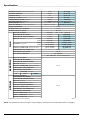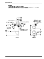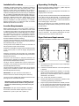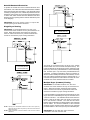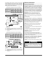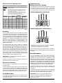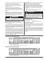
1
AD4545 / ML4545
Installation/Operator Manual
WARNING: For your safety the
information in this manual must be
followed to minimize the risk of fire or
explosion and to prevent property
damage, personal injury or death.
— Do not store or use gasoline or other
flammable vapors and liquids in the
vicinity of this or any other appliance.
— WHAT TO DO IF YOU SMELL GAS:
Do not try to light any appliance.
Do not touch any electrical switch;
do not use any phone in your
building.
● Clear the room, building or area of
all occupants.
● Immediately call your gas supplier
from a neighbor’s phone. Follow
the gas supplier’s instructions.
● If you cannot reach your gas
supplier, call the fire department.
●
●
— Installation and service must be
performed by a qualified installer,
service agency or the gas supplier.
AVERTISSEMENT: Assurez-vous de
bien suivre les instructions données dans
cette notice pour réduire au minimum le
risque d’incendie ou d’explosion ou pour
éviter tout dommage matériel, toute
blessure ou la mort.
—Ne pas entreposer ni utiliser d’essence
ni d’autres vapeurs ou liquides
inflammables à proximité de cet
appareil ou de tout autre appareil.
—QUE FAIRE SI VOUS SENTEZ UNE
ODEUR DE GAZ:
Ne pas tenter d’allumer d’appareils.
Ne touchez à aucun interrupteur. Ne
pas vous servir des téléphones se
trouvant dans le bâtiment.
● Évacuez la pièce, le bâtiment ou la
zone.
● Appelez immédiatement votre
fournisseur de gaz depuis un voisin.
Suivez les instructions du fournisseur.
● Si vous ne pouvez rejoindre le
fournisseur de gaz, appelez le service
des incendies.
●
●
—L’installation et l’entretien doivent être
assurés par un installateur ou un
service d’entretien qualifié ou par le
fournisseur de gaz.
American Dryer Corporation
88 Currant Road
Fall River MA 02720-4781 USA
Telephone: +1 (508) 678-9000 / Fax: +1 (508) 678-9447
e-mail: [email protected]
www.adclaundry.com
ADC Part No. 113608 - 12
Retain This Manual in a Safe Place for Future Reference
This product embodies advanced concepts in engineering, design, and safety. If this product is properly
maintained, it will provide many years of safe, efficient, and trouble free operation.
Only qualified technicians should service this equipment.
OBSERVE ALL SAFETY PRECAUTIONS displayed on the equipment or specified in the installation
manual included with the dryer.
The following “FOR YOUR SAFETY” caution must be posted near the dryer in a prominent location.
FOR YOUR SAFETY
POUR VOTRE SÉCURITÉ
Do not store or use gasoline
or other flammable vapors
and liquids in the vicinity of
this or any other appliance.
Ne pas entreposer ni utiliser d’essence
ni d’autres vapeurs ou liquides
inflammables à proximité de cet
appareil ou de tout autre appareil.
We have tried to make this manual as complete as possible and hope you will find it useful. The manufacturer
reserves the right to make changes from time to time, without notice or obligation, in prices, specifications,
colors, and material, and to change or discontinue models. The illustrations included in this manual may
not depict your particular dryer exactly.
IMPORTANT
For your convenience, log the following information:
DATE OF PURCHASE ________________________________________________ MODEL NO. _____________________
RESELLER’S NAME __________________________________________________________________________________
Serial Number(s) _____________________________________________________________________________________
____________________________________________________________________________________________________
Replacement parts can be obtained from your reseller or the ADC factory. When ordering replacement parts from the
factory, you can FAX your order to ADC at +1 (508) 678-9447 or telephone your order directly to the ADC Parts
Department at +1 (508) 678-9000. Please specify the dryer model number and serial number in addition to the
description and part number, so that your order is processed accurately and promptly.
These instructions are only valid if the following country code is on the appliance… If this code is not present on the
appliance, it is necessary to refer to the technical instructions which will provide the necessary information concerning
the modification of the appliance to the condition of use for the country.
In accordance with EN ISO 3166-1, the names of countries shall be represented by the following codes:
GB United Kingdom
IE Ireland
“IMPORTANT NOTE TO PURCHASER”
Information must be obtained from your local gas supplier on the
instructions to be followed if the user smells gas. These
instructions must be posted in a prominent location near the dryer.
2
American Dryer Corp.
113608 - 12
!
WARNING
In the State of Massachusetts, the following
installation instructions apply:
Proposition 65
■ Installations and repairs must be performed by
a qualified or licensed contractor, plumber, or
gasfitter qualified or licensed by the State of
Massachusetts.
Use of this product could expose you to substances
from fuel combustion that contain chemicals
known to the State of California to cause cancer,
birth defects and other reproductive harm.
IMPORTANT
You must disconnect and lockout the electric supply
and the gas supply or the steam supply before any
covers or guards are removed from the machine to allow
access for cleaning, adjusting, installation, or testing of
any equipment per OSHA standards.
Please observe all safety precautions displayed on the
equipment and/or specified in the installation manual
included with the dryer.
Before installation, check that the local distribution
conditions, nature of gas and pressure, and adjustment
of the appliances are compatible.
CAUTION
Dryer(s) should never be left unattended while in
operation.
“Caution: Label all wires prior to disconnection when
servicing controls. Wiring errors can cause improper
operation.”
«Attention: Au moment de l’entretien des commandes,
étiquetez tous les fils avant de les débrancher. Des
erreurs de câblage peuvent entraîner un fonctionnement
inadéquat et dangereux.»
WARNING
Children should not be allowed to play on or near the
dryer(s). Children should be supervised if near dryer(s)
in operation.
Under no circumstances should the dryer door
switch(es), lint door/drawer switch(es), or heat safety
circuit(s) ever be disabled.
Do not modify this appliance.
The dryer must never be operated with any of the back
guards or service panels removed. Personal injury or
fire could result.
The dryer must never be operated without the lint filter/
screen in place, even if an external lint collection system
is used.
If a hi-limit switch trips, a service call is required to
investigate the reason and resolve any issues that may
have caused the occurrence.
FOR YOUR SAFETY
Do not dry mop heads in the dryer. Do not use dryer
in the presence of dry cleaning fumes.
The dryers must not be installed or stored in an area
where it will be exposed to water and/or weather.
The wiring diagram for the dryer is located behind the
control panel.
113608 - 12
■ If using a ball valve, it shall be a T-handle type.
■ A flexible gas connector, when used, must not
exceed 3 feet.
Table of Contents _________________
Safety Precautions .................................................. 4
Specifications .......................................................... 6
Installation Procedures .......................................... 8
Location Requirements .......................................... 8
Unpacking / Setting Up .......................................... 8
Dryer Enclosure Requirements ............................. 8
Fresh Air Supply Requirements ............................. 9
Exhaust Requirements ........................................... 9
Electrical Information ........................................... 11
Gas Information ................................................... 12
Water Information ................................................ 14
Preparation for Operation / Start-Up .................... 15
Preoperational Test .............................................. 15
Preoperational Instructions .................................. 15
Shutdown Instructions .......................................... 16
Service / Parts Information ................................... 16
Service ................................................................. 16
Parts ..................................................................... 16
Warranty Information ............................................ 16
Returning Warranty Cards ................................... 16
Warranty ............................................................... 16
Returning Warranty Parts .................................... 16
Routine Maintenance ............................................ 17
Cleaning ............................................................... 17
Adjustments ......................................................... 18
Data Label Information ......................................... 18
Non-Coin Programming ........................................ 19
Coin Programming ................................................ 20
List of Acronyms ________________________
HVAC
in WC
L.C.D.
L.E.D.
L.P.
OSHA
R.M.A.
UL
www.adclaundry.com
Heating, Ventilating, and Air-Conditioning
Inches of Water Column
Liquid Crystal Display
Light Emitting Diode
Liquid Propane
Occupational Safety and Health Administration
Return Material Authorization
Underwriters Laboratory
3
Safety Precautions ____________________
!
WARNING
For your safety, the information in this manual must
be followed to minimize the risk of fire or explosion
and to prevent property damage, personal injury, or
loss of life.
The dryer must never be operated with any of the
back guards or service panels removed. Personal
injury or fire could result.
Failure to properly install, maintain, and/or operate
dryer according to this manual and operator’s
manuals included with dryer may result in conditions,
which can cause serious injury, death and/or property
damage.
!
Do not use heat for drying articles that contain
plastic, foam, sponge rubber, or similarly textured
rubber materials. Drying in a heated tumbler may
damage plastics or rubber and also may be a fire
hazard.
The possible presence of residual quantities of aggressive
or decomposed chemicals in the load may produce damage
to the machine and harmful fumes.
A program should be established for the inspection and
cleaning of lint in the burner area, exhaust ductwork, and
area around the back of the dryer. The frequency of
inspection and cleaning can best be determined from
experience at each location.
Do not store or use gasoline or other flammable vapors and
liquids in the vicinity of this or any other appliance.
Do not spray aerosols in the vicinity of this appliance while it
is in operation.
Purchaser and user should consult the local gas supplier for
proper instructions to be followed in the event the user smells
gas. The instructions should be posted in a prominent
location.
What To Do If You Smell Gas:
• Do not try to light any appliance.
!
The collection of lint in the burner area and exhaust
ductwork can create a potential fire hazard.
For personal safety, the dryer must be electrically grounded
in accordance with local codes and/or the National Electrical
Code ANSI/NFPA NO. 70-LATEST EDITION or in Canada,
the Canadian Electrical Codes Parts 1 & 2 CSA C22.1-1990
or LATEST EDITION.
• Do not use any phone in your building.
!
• Clear the room, building, or area of all occupants.
• Immediately call your gas supplier from a neighbor’s
phone. Follow the gas supplier’s instructions.
• If you cannot reach your gas supplier, call the fire
department.
Installation and service must be performed by a qualified
installer, service agency, or gas supplier.
Although the manufacturer produces a very versatile dryer,
there are some articles that, due to fabric composition or
cleaning method, should not be dried in it.
WARNING
Dry only water washed fabrics. Do not dry articles
spotted or washed in dry cleaning solvents,
combustible detergents, industrial chemicals, or “all
purpose” cleaner. Explosion could result.
Do not dry rags or articles coated or contaminated
with gasoline, kerosene, oil, paint, or wax. Explosion
could result.
Items that have been spotted or soaked with
vegetable or cooking oil constitute a fire hazard and
should not be placed in a tumble dryer.
Do not dry mop heads. Contamination by wax or
flammable solvents will create a fire hazard.
WARNING
Personal injury or fire could result should the dryer
door switch, lint door/drawer, or heat safety circuit
ever be disabled.
Remove articles from the dryer as soon as the drying cycle
has been completed.
Dryers must be exhausted to the outdoors.
4
WARNING
NOTE: Failure to electrically ground the dryer properly will
void the warranty.
• Do not touch any electrical switch.
!
WARNING
!
WARNING
Articles left in the dryer after the drying and cooling
cycles have been completed can create a fire hazard.
For safety, proper operation, and optimum performance, the
dryer must not be operated with a load less than 66% of its
rated capacity.
!
WARNING
You must disconnect and lockout the electric supply
and the gas supply or the steam supply before any
covers or guards are removed from the machine to
allow access for cleaning, adjusting, installation, or
testing of any equipment per OSHA standards.
IMPORTANT: The dryer must be installed in a location/
environment, which the ambient temperature remains
between 40° F (4.44° C) and 130° F (54.44° C).
American Dryer Corp.
113608 - 12
The operation of this appliance may affect the operation of
other types of gas appliances, which take their air for safe
combustion from the same room. If in doubt, consult the
appliance manufacturer(s).
NOTES _____________________________________________________
____________________________________________________________
Use this dryer only for its intended purpose, drying fabrics.
The “cool down” cycle of tumble dryers should be used to
reduce the temperature of the items. They should not be
removed from the tumble dryer or piled or stacked while hot.
Fabric softeners or similar products should not be used in a
tumbler dryer to eliminate the effects of static electricity unless
this practice is specifically recommended by the manufacturer
of the fabric softener or product.
!
WARNING
____________________________________________________________
____________________________________________________________
____________________________________________________________
____________________________________________________________
____________________________________________________________
____________________________________________________________
To reduce the risk of personal injury, install lockable
doors to prevent public access to the rear of the
dryers.
____________________________________________________________
____________________________________________________________
Exhaust duct outlet should be checked periodically for
blockages, and if any found, removed.
____________________________________________________________
IMPORTANT: A means of restraint must be used to prevent
straining of the gas supply when the appliance is moved.
____________________________________________________________
An external means of power removal (disconnect device)
must be provided by the installer.
____________________________________________________________
____________________________________________________________
CE ONLY
IMPORTANT: This appliance must only be installed and
operated in the country of destination indicated on the
dryer’s data plate. If the appliance is to be installed and
operated in a country other than the one indicated on the
data plate, a data plate amendment must be obtained from
American Dryer Corporation.
____________________________________________________________
____________________________________________________________
____________________________________________________________
____________________________________________________________
IEC335 applies.
!
____________________________________________________________
WARNING
____________________________________________________________
This appliance must only operate with the gas type
indicated on the dryer’s data plate. If the appliance
is converted (gas type is changed), a data plate
amendment must be obtained from American Dryer
Corporation.
This appliance may cause spillage of products of
combustion from an open-flue appliance fitted in the
same room, and that such an appliance shall be
tested for clearance of products with the appliance
in operation and all windows and doors closed.
____________________________________________________________
____________________________________________________________
____________________________________________________________
____________________________________________________________
____________________________________________________________
____________________________________________________________
____________________________________________________________
____________________________________________________________
____________________________________________________________
____________________________________________________________
____________________________________________________________
____________________________________________________________
113608 - 12
www.adclaundry.com
5
Specifications _______________________________________________________________________
GAS
MAXIMUM CAPACITY (DRY WEIGHT) PER POCKET
TUMBLER DIAMETER
TUMBLER DEPTH
TUMBLER VOLUME PER POCKET
TUMBLER/DRIVE MOTOR PER POCKET
BLOWER/FAN MOTOR PER POCKET
DOOR OPENING (DIAMETER)
DOOR SILL HEIGHT TOP POCKET / BOTTOM POCKET
WATER CONNECTION
DRYERS PER 20’/40’ CONTAINER
DRYERS PER 48’/53’ TRUCK
VOLTAGE AVAILABLE
APPROXIMATE NET WEIGHT
APPROXIMATE SHIPPING WEIGHT
AIRFLOW PER POCKET
HEAT INPUT
PER POCKET
EXHAUST CONNECTION
60
50
60
50
Hz
Hz
Hz
Hz
(DIAMETER) PER POCKET
STEAM
ELECTRIC
COMPRESSED AIR CONNECTION
COMPRESSED AIR VOLUME
INLET PIPE CONNECTION
20.41 kg
45 lb
83.19 cm
32-3/4”
76.20 cm
30”
413.43 L
14.6 cu ft
0.56 kW
3/4 hp
BLOWER DRIVEN BY TUMBLER MOTOR
68.6 cm
27”
127.64 cm / 26.04 cm
50-1/4” / 10-1/4”
N / A
8 / 16
25 / 27
120-480V
1,3ø 2,3w
50/60 Hz
460.40 kg
1,015 lb
476.27 kg
1,050 lb
16.99 cmm
600 cfm
14.16 cmm
500 cfm
28,230 kcal/hr
112,000 Btu/hr
23,451 kcal/hr
93,000 Btu/hr
(2) 20.32 cm
(1) 25.4 cm
(2) 8” Standard
(1) 10” Optional
N / A
N / A
3/4” M.N.P.T.
3/4” F.B.S.P.T. (CE and Australia Only)
VOLTAGE AVAILABLE
APPROXIMATE NET WEIGHT
APPROXIMATE SHIPPING WEIGHT
AIRFLOW PER POCKET
EXHAUST CONNECTION (DIAMETER) PER POCKET
COMPRESSED AIR CONNECTION
COMPRESSED AIR VOLUME
OVEN SIZE PER POCKET
kcal/hr
kW
Btu/hr
VOLTAGE AVAILABLE
APPROXIMATE NET WEIGHT
APPROXIMATE SHIPPING WEIGHT
AIRFLOW PER POCKET
STEAM CONSUMPTION PER POCKET
OPERATING STEAM PRESSURE
EXHAUST CONNECTION (DIAMETER) PER POCKET
COMPRESSED AIR CONNECTION
COMPRESSED AIR VOLUME
BOILER HORSEPOWER (NORMAL LOAD) PER POCKET
SUPPLY CONNECTION PER POCKET
RETURN CONNECTION PER POCKET
Shaded areas are stated in metric equivalents
N / A
N / A
6/27/11
NOTE: The manufacturer reserves the right to make changes in specifications at any time without notice or obligation.
6
American Dryer Corp.
113608 - 12
Specifications _______________________________________________________________________
113608 - 12
www.adclaundry.com
7
Installation Procedures _______________
Unpacking / Setting Up ________________
Installation should be performed by competent professional
in accordance with local, state, and country codes. In the
absence of these codes, the installation must conform to
applicable American National Standards: ANSI Z223.1LATEST EDITION (National Fuel Gas Code) or ANSI/NFPA
NO. 70-LATEST EDITION (National Electrical Code) or in
Canada, the installation must conform to applicable Canadian
Standards: CAN/CGA-B149.1-M91 (Natural Gas) or CAN/
CGA-B149.2-M91 (L.P. Gas) or LATEST EDITION (for
General Installation and Gas Plumbing) or Canadian
Electrical Codes Parts 1 & 2 CSA C22.1-1990 or LATEST
EDITION (for Electrical Connections).
Remove protective shipping material (i.e., plastic wrap and
optional shipping box) from the dryer.
Location Requirements _______________
Before installing the dryer, be sure the location conforms to
local codes and ordinances. In the absence of such codes
or ordinances the location must conform with the National
Fuel Gas Code ANSI.Z223.1 LATEST EDITION, or in Canada,
the installation must conform to applicable Canadian
Standards: CAN/CGA-B149.1-M91 (Natural Gas) or
CAN/CGA-B149.2-M91 (L.P. Gas) or LATEST EDITION (for
General Installation and Gas Plumbing).
The dryer must be installed on a sound level floor capable of
supporting its weight. Carpeting must be removed from the
floor area that the dryer is to rest on.
IMPORTANT: Dryer must be transported and handled in an
upright position at all times.
The dryer can be moved to its final location while still attached
to the skid or with the skid removed. To remove the skid
from the dryer, locate and remove the 4 bolts securing the
base of the dryer to the wooden skid. Bolts are located next
to the leveling legs in each corner.
With the skid removed, use caution and assure all four
leveling legs are fully retracted, if the dryer is to be slid into
its final position.
Leveling Dryer
The dryer is equipped with four leveling legs, one at each
corner of the base. For optimum performance the dryer
should be level front-to-back and side-to-side.
Dryer Enclosure Requirements _______
Bulkheads and partitions should be made of noncombustible
material.
The dryer must not be installed or stored in an area where it
will be exposed to water and/or weather.
Provisions for adequate air supply must be provided as noted
in this manual (refer to Fresh Air Supply Requirements
section).
Clearance provisions must be made from combustible
construction as noted in this manual (refer to Dryer Enclosure
Requirements section).
Provisions must be made for adequate clearances for
servicing and for operation as noted in this manual (refer to
Dryer Enclosure Requirements section).
The dryer must be installed with a proper exhaust duct
connection to the outside as noted in this manual (refer to
Exhaust Requirements section).
A
The requirement to allow the door to open completely is
33.5-inches (85.1 cm).
B
A minimum overhead clearance of 12-inches (30.48 cm)
is required.
C
Dryer should be positioned a minimum of 12-inches
(30.48 cm) away from the nearest obstruction. 24-inches
(60.96 cm) is recommended for ease of installation,
maintenance, and service.
The dryer must be installed with adequate clearance for air
openings into the combustion chamber.
D
1/16” (1.5875 mm) minimum is required.
E
CAUTION: This dryer produces combustible lint and
must be exhausted to the outdoors. Every 6 months,
inspect the exhaust ducting and remove any lint
buildup.
Flooring should be level or below dryer cabinet for ease
of removing panels during maintenance.
F
Dryers may be positioned sidewall to sidewall, however
a 1/16” (1.5875 mm) minimum allowance must be made
for the opening and closing of the control door, along
with the removal of panels during maintenance.
The dryer must be located in an area where correct exhaust
venting can be achieved as noted in this manual (refer to
Exhaust Requirements section).
IMPORTANT: The dryer should be located where a
minimum amount of exhaust ducting will be necessary.
IMPORTANT: The dryer must be installed in a location/
environment, which the ambient temperature remains
between 40° F (4.44° C) and 130° F (54.44° C).
8
American Dryer Corp.
113608 - 12
Fresh Air Supply Requirements _______
Exhaust Requirements ________________
This appliance may only be installed in a room that meets
the appropriate ventilation requirements specified in the
national installation regulations.
Exhaust ductwork should be designed and installed by a
qualified professional. Improperly sized ductwork will create
excessive back pressure, which results in slow drying,
increased use of energy, and shutdown of the burner by the
airflow (sail) switch, burner hi-limits, or lint chamber hi-limit
protector thermostat. The dryer must be installed with a
proper exhaust duct connection to the outside.
When the dryer is operating, it draws in room air, heats it,
passes this air through the tumbler, and exhausts it out of
the building. Therefore, the room air must be continually
replenished from the outdoors. If the make-up air is
inadequate, drying time and drying efficiency will be adversely
affected. Ignition problems and sail switch “fluttering”
problems may result, as well as premature motor failure from
overheating. The dryer must be installed with provisions for
adequate combustion and make-up air supply.
Air supply (make-up air) must be given careful consideration
to ensure proper performance of each dryer. Fresh air
ventilation openings shall not be blocked and/or sealed. As
a general rule, an unrestricted air entrance from the outdoors
of 224 inch2 (1,445 cm2) is required. (Based on 1 inch2 [6.5
cm2] per 1,000 Btu [252 kcal].)
It is not necessary to have a separate make-up air opening
for each dryer. Common make-up air openings are
acceptable. However, they must be set up in such a manner
that the make-up air is distributed equally to all the dryers.
The design of the flue system shall be such that any
condensate formed when operating the appliance from cold
shall either be retained and subsequently re-evaporated or
discharged.
CAUTION: This dryer produces combustible lint and
must be exhausted to the outdoors.
Improperly sized or installed exhaust ductwork can
create a potential fire hazard.
The ductwork should be laid out in such a way that the
ductwork travels as directly as possible to the outdoors with
as few turns as possible. Single or independent dryer venting
is recommended. It is suggested that the use of 90° turns be
avoided; use 30° and/or 45° bends instead. The radius of
the elbows should preferably be 1-1/2 times the diameter of
the duct. All ductwork should be smooth inside with no
projections from sheet metal screws or other obstructions,
which will collect lint. When adding ducts, overlap the duct
being connected. All ductwork joints must be taped to prevent
moisture and lint from escaping into the building. Inspection
doors should be installed at strategic points in the exhaust
ductwork for periodic inspection and cleaning of lint from the
ductwork.
IMPORTANT: It is recommended that exhaust or booster
fans not be used in the exhaust ductwork system.
Exhaust back pressure measured by a manometer/
magnehelic in the exhaust duct must be no less than 0 and
must not exceed 0.6 in WC (1.48 mb).
NOTE: When the exhaust ductwork passes through a wall,
ceiling, or roof made of combustible materials, the opening
must be 2-inches (5.08 cm) larger than the duct (all the
way around). The duct must be centered within this
opening.
A = 20-inches (50.80 cm)
B = 22.5-inches (57.15 cm)
EXAMPLE: For a bank of 4 dryers, 2 unrestricted openings
measuring 20-inches by 22.5-inches (50.80 cm by 57.15 cm)
are acceptable.
As per the National Fuel Gas Code, “Exhaust ducts for
type 2 clothes dryers shall be constructed of sheet metal or
other noncombustible material. Such ducts shall be
equivalent in strength and corrosion resistance to ducts
made of galvanized sheet steel not less than 26 gauge
(0.0195-inches [0.50 mm]) thick.”
To compensate for the use of registers or louvers used over
the openings, this area must be increased by approximately
33%. Make-up air openings should not be located in an area
directly near where exhaust vents exit the building.
The ductwork for this appliance must be suitable for the
appliance category in accordance with national installation
regulations of the country of destination.
Allowances must be made for remote or constricting
passageways or where dryers are located at high altitudes
or predominantly low pressure areas.
IMPORTANT: Make-up air must be free of dry cleaning
solvent fumes. Make-up air that is contaminated by dry
cleaning solvent fumes will result in irreparable damage to
the motors and other dryer components.
NOTE: Component failure due to dry cleaning solvent
fumes will void the warranty.
113608 - 12
www.adclaundry.com
9
Outside Ductwork Protection
To protect the outside end of the horizontal ductwork from
the weather, a 90° elbow bent downward should be installed
where the exhaust exits the building. If the ductwork travels
vertically up through the roof, it should be protected from the
weather by using a 180° turn to point the opening downward.
In either case, allow at least twice the diameter of the duct
between the duct opening and the nearest obstruction (refer
to the diagram).
IMPORTANT: Do not use screens, louvers, or caps on the
outside opening of the exhaust ductwork.
Single Dryer Venting
IMPORTANT: For extended ductwork runs, the crosssectional area of the ductwork can only be increased to an
extent. When the ductwork approaches the maximum
limits as noted in this manual, a professional HVAC firm
should be consulted for proper venting information.
A = 20 feet (6.10 meters)
B = 8-inches (20.32 cm)
The length of the ductwork from the dryer to the outside
exhaust outlet must not exceed 20 feet (6.09 meters). The
minimum diameter of this ductwork must be at least 8-inches
(20.32 cm) when each pocket/tumbler is vented individually
and 10-inches (25.4 cm) when both pockets/tumblers are
combined. Including tumbler/dryer elbow connections or
elbows used for outside protection from the weather, no more
than 3 90° elbows should be used in the exhaust duct run. If
more than the equivalent of 3 90° elbows are used, the crosssectional area of the ductwork must be increased.
A = 20 feet (6.10 meters)
B = 10-inches (25.4 cm)
C = 8-inches (20.32 cm)
Multiple Dryer (Common) Venting
IMPORTANT: For extended ductwork runs, the crosssectional area of the ductwork can only be increased to an
extent. When the ductwork approaches the maximum
limits as noted in this manual, a professional HVAC firm
should be consulted for proper venting information.
NOTE 1 Opening from combustible materials must be 2-inches (5.08 cm)
larger than the duct (all the way around). The duct must be centered
within this opening.
NOTE 2 Distance should be 2 times the diameter of the duct to the nearest
obstruction.
10
If it is not feasible to provide separate exhaust ducts for each
dryer, ducts from individual dryers may be channeled into a
“common main duct.” The individual ducts should enter the
bottom or side of the main duct at an angle not more than
45° in the direction of airflow. The main duct should be
tapered, with the diameter increasing before each individual
duct is added. The minimum diameter of the individual
ductwork must be at least 8-inches (20.32 cm) for individual
pockets/tumblers or 10-inches (25.4 cm) for individual dryers.
IMPORTANT: No more than four dryers should be
connected to one main common duct.
American Dryer Corp.
113608 - 12
The illustration below shows the minimum cross-sectional
area for multiple dryer round or square venting. These figures
must be increased if the main duct run from the last dryer to
where it exhausts to the outdoors is longer than 20 feet (6.09
meters) or has more than 1 elbow in it.
Multiple Dryer Venting with 10-Inch (25.4 cm) Diameter
1,200 cfm (33.98 cmm) Exhaust Connections at Common Duct
NUMBER OF DRYERS
SQ IN
SQ CM
IN
MINIMUM ROUND
DUCT DIAMETER
CM
4
254
1638
18
45.72
MINIMUM CROSSSECTIONAL AREA
3
200
1290
16
40.64
2
155
999
14
35.56
1
80
516
10
25.4
Electrical Information _________________
Electrical Requirements
All electrical connections must be made by a properly licensed
and competent electrician. This is to ensure that the electrical
installation is adequate and conforms to local, state, and
national regulations or codes of the country of destination.
In the absence of such codes, all electrical connections,
materials, and workmanship must conform to the applicable
requirements of the National Electrical Code ANSI/NFPA NO.
70-LATEST EDITION or in Canada, the Canadian Electrical
Codes Parts 1 & 2 CSA C22.1-1990 or LATEST EDITION.
IMPORTANT: Failure to comply with these codes or
ordinances, and/or the requirements stipulated in this
manual can result in personal injury or component failure.
A = 10-inches (25.4 cm) B = 20 feet (6.09 meters)
NOTE: Component failure due to improper installation will
void the warranty.
Each pocket should be connected to an independently
protected branch circuit. The dryer must be connected with
copper wire only. Do not use aluminum wire, which could
cause a fire hazard. The copper conductor wire/cable must
be of proper ampacity and insulation in accordance with
electric codes for making all service connections.
NOTE: The use of aluminum wire will void the warranty.
An individual ground circuit must be provided to each
pocket, do not daisy chain.
Component failure due to improper voltage application will
void the warranty.
NOTE 1 Opening from combustible materials must be 2-inches (5.08 cm)
larger than the duct (all the way around). The duct must be centered
within this opening.
NOTE 2 Distance should be 2 times the diameter of the duct to the nearest
obstruction.
Multiple Dryer Venting with 8-Inch (20.32 cm) Diameter
600 cfm (16.99 cmm) Exhaust Connections at Common Duct
NUMBER OF DRYERS
SQ IN
SQ CM
IN
MINIMUM ROUND
DUCT DIAMETER
CM
MINIMUM CROSSSECTIONAL AREA
8
7
254
1638
18
45.72
6
5
200
1290
16
40.64
4
3
155
999
14
35.56
2
1
80
516
10
25.4
The manufacturer reserves the right to make changes in
specifications at any time without notice or obligation.
IMPORTANT: A separate protected circuit must be
provided to each pocket.
It is necessary to have a power disconnect for each
pocket. These disconnects must be located within 30 feet
(9 meters) of the unit and also be identified as being one of
two power sources supplying a dryer.
The dryer must be connected to the electric supply shown
on the data label. In the case of 208 VAC or 230/240 VAC,
the supply voltage must match the electric service
specifications of the data label exactly.
The wire size must be properly sized to handle the related
current.
!
WARNING
208 VAC and 230/240 VAC are not the same. Any
damage done to dryer components due to improper
voltage connections will automatically void the
warranty.
A = 8-inches (20.32 cm)
B = 20 feet (6.09 meters)
NOTE 1 Opening from combustible materials must be 2-inches (5.08 cm)
larger than the duct (all the way around). The duct must be centered
within this opening.
NOTE 2 Distance should be 2 times the diameter of the duct to the nearest
obstruction.
113608 - 12
www.adclaundry.com
11
Electrical Service Specifications
ELECTRICAL SERVICE SPECIFICATIONS (PER POCKET)
IMPORTANT:
NOTES:
A.
B.
C.
208 VAC AND 230/240 VAC ARE NOT THE SAME. When ordering,
specify exact voltage.
When fuses are used they must be dual element, time delay, current
limiting, class RK1 or RK5 ONLY. Calculate/determine correct fuse
value, by applying either local and/or National Electrical Codes to
listed appliance amp draw data.
Circuit breakers are thermal-magnetic (industrial) motor curve type
ONLY. For others, calculate/verify correct breaker size according to
appliance amp draw rating and type of breaker used.
Circuit breakers for 3-phase (3ø) dryers must be 3-pole type.
APPROX.
AMP DRAW
PHASE
WIRE
SERVICE
120
1ø
2
12
—
15
208
1ø
2
7
—
15
50 Hz
The electrical input connections are made into the rear service
box located at the top rear of the dryer. The ground
connection is made to the copper lug, also provided in this
box. To gain access, the service box cover must be removed.
120-240V Application with Neutral
CIRCUIT
BREAKER
SERVICE
VOLTAGE
60 Hz
Single-Phase (1ø)
Wiring Connections / Hookup
230
1ø
2
6.5
—
15
220
1ø
2
—
5
15
230 / 240
1ø
2
—
4.9
15
208
3ø
3
3
—
15
240
3ø
3
3.2
—
15
480
3ø
3
2.1
—
15
5/29/14
208-240V Application without Neutral
Grounding
A ground (earth) connection must be provided and installed
in accordance with local, state, and national regulations or
codes of the country of destination. In the absence of these
codes, grounding must conform to applicable requirements
of the National Electrical Code ANSI/NFPA NO. 70-LATEST
EDITION, or in Canada, the installation must conform to
applicable Canada Standards: Canadian Electrical Codes
Parts 1 & 2 CSA C22.1-1990 or LATEST EDITION. The
ground connection may be to a proven earth ground at the
location service panel.
For added personal safety, when possible, it is suggested
that a separate ground wire (size per local codes) be
connected from the ground connection of the dryer to a
grounded cold water pipe. Do not ground to a gas pipe or
hot water pipe. The grounded cold water pipe must have
metal-to-metal connection all the way to the electrical ground.
If there are any nonmetallic interruptions, such as, a meter,
pump, plastic, rubber, or other insulating connectors, they
must be jumped out with a wire (size per local codes) and
securely clamped to bare metal at both ends.
IMPORTANT: For personal safety and proper operation,
the dryer must be grounded.
Provisions are made for ground connection in each dryer at
the electrical service connection area.
Electrical Connections
A wiring diagram is located behind the control panel for
connection data.
If local codes permit, power to the dryer can be made by the
use of a flexible UL listed power cord/pigtail (wire size must
conform to rating of dryer), or the dryer can be hard wired
directly to the service breaker panel. In both cases, a strain
relief must be installed where the wiring enters the dryer.
For CE Models Only
The means for disconnection from the supply must be
incorporated into wiring having a minimum contact separation
of 3.0 mm in all poles.
12
CAUTION: The dryer must be grounded. A ground
lug has been provided for this purpose.
Input connection wiring must be sized properly to handle the
dryer’s current draw. This information is printed on the dryer’s
data label.
Gas Information ______________________
It is your responsibility to have all plumbing connections,
materials, and workmanship conform to local and state
regulations or codes of the country of destination. In the
absence of such codes, all plumbing connections, materials,
and workmanship must conform to the applicable local
requirements. In the USA this is the National Fuel Gas Code
ANSI Z223.1-LATEST EDITION, or in Canada, the Canadian
Installation Codes CAN/CGA-B149.1-M91 (Natural Gas) or
CAN/CGAB149.2-M91 (L.P. Gas) or LATEST EDITION.
In Australia, the fuel gas code is AS 5601 / AG 601, local
authority, gas, electricity, and any other relevant statutory
regulations.
It is important that gas pressure regulators meet applicable
pressure requirements, and that gas meters be rated for the
total amount of all the appliance Btu being supplied.
IMPORTANT: Failure to comply with these codes or
ordinances, and/or the requirements stipulated in this
manual, can result in personal injury and improper
operation of the dryer.
American Dryer Corp.
113608 - 12
For ease of service, the individual gas supply line of each
dryer must have its own manual shutoff valve.
Failure to isolate or disconnect the dryer from supply as
noted can cause irreparable damage to the gas valve,
voiding the warranty.
The dryer and its individual shutoff valve must be
disconnected from the gas supply piping system during
any pressure testing of that system at test pressures in
excess of 1/2 psig (3.5 kPa) for non-CE dryers or 50 mb for
CE dryers.
NOTE: The dryer must be isolated from the gas supply
piping system by closing its individual manual shutoff valve
during any pressure test of the gas supply system at test
pressures equal to or less than 1/2 psig (3.5 kPa) for nonCE dryers or 50 mb for CE dryers.
!
WARNING
Fire or explosion could result due to failure of
isolating or disconnecting the gas supply as noted.
NOTE: Undersized gas piping will result in ignition
problems, slow drying, increased use of energy, and can
create a safety hazard.
The dryer must be connected to the type of heat/gas indicated
on the data label and pressure must be confirmed. If this
information does not agree with the type of gas available, do
not operate the dryer. Contact the reseller who sold the dryer
or contact the manufacturer.
The input ratings shown on the data label are for elevations
up to 2,000 feet (610 meters), unless elevation requirements
of over 2,000 feet (610 meters) were specified at the time
the dryer order was placed with the factory. The adjustment
or conversion of dryers in the field for elevations over 2,000
feet (610 meters) is made by changing each burner orifice.
If this conversion is necessary, contact the reseller who sold
the dryer or contact the manufacturer.
IMPORTANT: If connection to this appliance is made with
a flexible hose, it must be suitable for the appliance
category in accordance with national installation
regulations of the country of destination, and if in doubt the
installer must contact the supplier. The manufacturer of
this appliance does not recommend the use of flexible gas
supply line/hose. An external gas supply shutoff must be
provided.
Pipe joint compounds that resist the action of natural,
propane, and butane gases must be used.
!
WARNING (CE Dryers Only)
This appliance must only be operated with the gas
type indicated on the dryer’s data plate. If the
appliance is converted (gas type changed), a data
plate amendment must be obtained from American
Dryer Corporation for CE approved units.
Gas Connections
Inlet connection ........ 3/4” M.N.P.T.
Inlet supply size ........ 3/4” Diameter Pipe (minimum)
Piping / Connections
The dryer is provided with a 3/4” N.P.T. inlet pipe connection
at the rear of the dryer. It is recommended that a gas shutoff
valve be provided to the gas supply line of each dryer for
ease in servicing.
The size of the main gas supply line (header) will vary
depending on the distance this line travels from the gas meter
or, in the case of L.P. gas, the supply tank, other gas-operated
appliances on the same line, etc. Specific information
regarding supply line size should be determined by the gas
supplier.
Heat Input / Orifice (Injector) Data
Gas Specifications for CSA Approved 60 Hz Dryers**
B tu /ft 3
in WC
Btu/hr
kW
DMS
mm
Orifice
(Injector)
Quantity
per Pocket
Natural
1,000
6.0-12.0
112,000
32.82
5
5.220
1
3.5
*Liquid Propane
2,500
11.0
112,000
32.82
31
3.048
1
10.5
Gas
Type
Nominal
Heating Value
Supply
Pressure
Gross Heat Input
per Pocket
Orifice Size
Burner
Pressure
in WC
Shaded areas are stated in metric equivalents
* Gas valve’s internal regulator disabled.
** Consult factory for elevations over 2,000 feet (610 meters) for correct orifice size.
Heat Input / Orifice (Injector) Data
Gas Specifications for Non-CE and Non-AGA Approved 50 Hz Dryers**
B tu /ft 3
in WC
Btu/hr
kW
DMS
mm
Orifice
(Injector)
Quantity
per Pocket
Natural
1,000
6.0-12.0
93,000
27.26
13
4.699
1
3.5
*Liquid Propane
2,500
11.0
93,000
27.26
34
2.819
1
10.5
Gas
Type
Nominal
Heating Value
Supply
Pressure
Gross Heat Input
per Pocket
Orifice Size
Burner
Pressure
in WC
Shaded areas are stated in metric equivalents
* Gas valve’s internal regulator disabled.
** Consult factory for elevations over 2,000 feet (610 meters) for correct orifice size.
113608 - 12
www.adclaundry.com
13
NOTE: Undersized gas supply piping can create a low or
inconsistent pressure, which will result in erratic operation
of the burner ignition system.
TYPICAL NATURAL GAS INSTALLATION
IMPORTANT: It is your responsibility to have all plumbing
connections made by a qualified professional to ensure
that the plumbing installation is adequate and conforms to
local, state, and federal regulations or codes.
It is the installer’s or owner’s responsibility to see that the
required water pressure, pipe size, or connections are
provided. The manufacturer assumes no responsibility if
the fire suppression system is not connected, installed, or
maintained properly.
Installation
Water Supply
The fire suppression system must be supplied with a minimum
water pipe size of 1/2-inch (12.7 mm) and be provided with
40 psi +/- 20 psi (2.75 bar +/- 1.37 bar) of pressure.
If the rear area of the dryer or the water supply is located in
an area where it will be exposed to cold/freezing
temperatures, provisions must be made to protect these water
lines from freezing.
TYPICAL L.P. GAS INSTALLATION
!
WARNING
If the water in the supply line or water solenoid valve
freezes, the fire suppression system will be
inoperative!!
Water Connections
The water connection is made to the 3/4”-11.5 NH hose
adaptor, which is shipped in the tumbler and must be installed
to the 1/2” N.P.T. water connection, located at the upper rear
of the dryer. A flexible supply line/coupling must be used in
an effort to avoid damaging the electric water solenoid valve.
Consistent gas pressure is essential at all gas connections.
It is recommended that a 3/4-inch (19.05 mm) pipe gas loop
be installed in the supply line servicing a bank of dryers. An
in-line pressure regulator must be installed in the gas supply
line (header) if the (natural) gas pressure exceeds 13.0 in
WC (32.34 mb) pressure.
A plugged tap, accessible for a pressure gauge connection,
must be installed in the main gas supply line immediately
upstream of the dryers.
IMPORTANT: Pipe joint compounds that resist the action
of natural, L.P., and butane gases must be used.
Test all connections for leaks by brushing on a soapy
water solution (liquid detergent works well).
!
WARNING
Never test for leaks with a flame!!!
Water Information _____________________
Before You Start
Check Local Codes and Permits
Call your local water company or the proper municipal
authority for information regarding local codes.
14
NOTE: The 3/4”-11.5 NH is a standard hose coupling
screw thread. It is not to be confused with 3/4” N.P.T. The
sealing of an NH connection is made with a washer
opposed to the mating threads of an N.P.T. assembly. The
2 thread designs are not compatible.
It is recommended that a filter or strainer be installed in the
water supply line.
IMPORTANT: Flexible supply line/coupling must be used.
Solenoid valve failure due to hard plumbing connections
will void warranty.
The dryer is to be connected to the water mains using a
new hose set and the old hose set should not be reused.
Optional Manual Bypass
Provisions are made in the dryer’s fire suppression system
for the installation of an optional manual bypass. The
connections for the manual bypass are made at the “cross”
or “four way” fitting located in the outlet supply side of the
water solenoid valve. The manual ball cock shutoff valve
must be located outside of the dryer at a distance from the
dryer where it is easily accessible. The use and connection
of this manual bypass is at the option or discretion of the
owner.
The water connection for the manual bypass is made to the
“cross” or “four way” fitting, which has a 3/8” F.N.P.T. and a
coupling must be used to provide the minimum 1/2-inch (12.7
mm) supply (feed) line.
American Dryer Corp.
113608 - 12
Electrical Requirements
No independent external power source or supply connection
is necessary. The 24-volt power to operate the fire
suppression system is accomplished internally in the dryer
(from the dryer controls).
!
WARNING
NOTE: During the purging period, check to be sure that all
gas shutoff valves are open.
A gas pressure test should be taken at the gas valve pressure
tap of each dryer to ensure that the water column pressure is
correct and consistent.
NOTE: Water column pressure requirements (measured at
the pressure tap of the gas valve body) must be verified.
Electrical power must be provided to the dryer at all
times. If the main electrical power supply to the dryer
is disconnected, the fire suppression system is
inoperative!!
Preparation for Operation / Start-Up _
The following items should be checked before attempting to
operate the dryer:
• Read all “CAUTION,” “WARNING,” and “DIRECTION”
labels attached to the dryer.
IMPORTANT: In most cases there is no regulator provided
in an L.P. dryer. The water column pressure must be
regulated at the source (L.P. tank), or an external regulator
must be added to each dryer.
Safety Related Circuits
Make a complete operational check of all safety related
circuits:
• Door Switch(es)
• Hi-Limit Thermostats
• Check incoming supply voltage to be sure that it is the
same as indicated on the data label. In the case of 208
VAC or 230/240 VAC, the supply voltage must match the
electric service exactly.
• Sail Switch
• GAS MODELS – Check to ensure that the dryer is
connected to the type of heat/gas indicated on the dryer
data label.
The tumbler is treated with a protective coating. We suggest
dampening old garments or cloth material with a solution of
water and nonflammable mild detergent and tumbling them
in the tumbler to remove this coating.
• GAS MODELS – Be sure that all gas shutoff valves are
in the open position.
• Be sure all back panels (guards) and electric box covers
are in place.
Make a complete operational check of all operating controls.
Tumbler Coating
Microprocessor Programs / Selections
• Be sure the lint door/drawer is securely in place.
Each microprocessor controller (computer) has been
preprogrammed by the factory with the most commonly used
parameter (program) selections. If computer program
changes are required, refer to the computer programming
manual, which was shipped with the dryer.
• Rotate the tumbler (drum) by hand to be sure it moves
freely.
Preoperational Instructions __________
• Check bolts, nuts, screws, terminals, and fittings for
tightness and security.
IMPORTANT: For more detailed information regarding the
microprocessor controller (computer), refer to the
microprocessor user’s manual included with the dryer.
• Be sure the service doors are closed and securely in
place.
• Check that the vent is connected to the dryer and is
exhausted to the outdoors.
Preoperational Test ___________________
All dryers are thoroughly tested and inspected before leaving
the factory. However, a preoperational test should be
performed before the dryer is publicly used. It is possible
that adjustments have changed in transit or due to marginal
location (installation) conditions. Installer must instruct the
user on how to correctly operate the dryer before leaving.
Turn on electric power to the dryer.
Refer to the Operating Instructions for starting your particular
model dryer.
Gas Dryers
Open all shutoff valves.
When a gas dryer is first started (during initial start-up), it
has a tendency not to ignite on the first ignition attempt. This
is because the gas supply piping is filled with air, so it may
take a few minutes for the air to be purged from the lines.
113608 - 12
Coin Models
Microprocessor Controller (Computer)
When the microprocessor controller (computer) is in the ready
state, the L.C.D. screen will display “Ready, Insert $XX.XX
(amount) to Start”.
Insert coin(s). Once the correct “Amount to Start” has been
inserted, the L.C.D. will display “Select Temperature”.
Select temperature by pressing “HI,” “MED,” or “LO.” The
cycle will start and the L.C.D. will display the Dry Cycle
selected and the remaining time.
The dryer will continue through the drying and cooling cycles,
until the vended time has expired.
NOTE: To stop the dryer, open main door. Continuation of
the cycle will resume only after the door has been closed
and any one of the three temperature selections is
pressed.
www.adclaundry.com
15
Non-Coin Models
Warranty Information _________________
Microprocessor Controller (Computer)
Returning Warranty Cards
The L.E.D. display reads “READY” (no cycle in progress).
Press the letter on the keypad corresponding to the cycle
desired (e.g. key “D”).
The dryer will then start (i.e. blower, tumbler, and heat).
The L.E.D. display will read MANUAL DRYING CYCLE D,
___MIN REMAIN.
NOTE: The dryer can be stopped at any time by pressing
the “STOP/CLEAR” key, at this time the dryer will go into a
cycle pause. If the “STOP/CLEAR” key is pressed again at
this point, the cycle that was in progress will be cancelled
and returned to the “READY” state.
When the programmed drying time has expired, the noncoin microprocessor controller (computer) will proceed into
the Cool Down Cycle.
Once the Cool Down Cycle begins at the end of the heat
cycle, the L.E.D. display will read COOL DOWN TEMP __/
__ MINUTES remaining. At the end of the heat cycle, the
dryer will shut off the heat and continue the fan and tumbler
until the Cool Down Time or temperature is reached.
Shutdown Instructions ________________
Before any dryer leaves the factory test area, a warranty card
is placed on the inside of the main door glass. These warranty
cards are intended to serve the customer where we record
the individual installation date and warranty information to
better serve you should you file a warranty claim.
If a warranty card did not come with your dryer, contact the
Warranty Department or the Service Department at +1 (508)
678-9000.
IMPORTANT: A separate warranty card must be completed
and returned for each individual dryer.
NOTE: Be sure to include the installation date when
returning the warranty card(s).
Warranty
For a copy of the commercial warranty covering your particular
dryer(s), contact the reseller from whom you purchased the
equipment and request a dryer warranty form. If the reseller
cannot be contacted or is unknown, warranty information can
be obtained from the factory by contacting the Warranty
Department at +1 (508) 678-9000.
If the dryer is to be shutdown (taken out of service) for a
period of time, the following must be performed:
NOTE: Whenever contacting the factory for warranty
information, be sure to have the dryer’s model number and
serial number available so that your inquiry can be
handled in an expeditious manner.
Discontinue power to the dryer either at the external
disconnect switch or the circuit breaker.
Returning Warranty Parts
Discontinue the heat supply:
All dryer or parts warranty claims or inquiries should be
addressed to the Warranty Parts Department. To expedite
processing, the following procedures must be followed:
Gas Models – Discontinue the gas supply.
Shut off external gas supply shutoff valve.
Shut off internal gas supply shutoff valve located in the gas
valve burner area.
Service / Parts Information ___________
Service
Service must be performed by a qualified trained technician.
If service is required, contact the reseller from whom the
equipment was purchased. If the reseller cannot be contacted
or is unknown, contact the Service Department for a reseller
in your area.
NOTE: When contacting the Service Department, be sure
to give them the correct model number and serial number
so that your inquiry is handled in an expeditious manner.
Parts
Replacement parts should be purchased from the reseller
from whom the equipment was purchased. If the reseller
cannot be contacted or is unknown, contact the Parts
Department for a reseller in your area. Parts may also be
purchased directly from the factory by calling the Parts
Department at +1 (508) 678-9000 or you may FAX in your
order at +1 (508) 678-9447.
NOTE: When ordering replacement parts from the reseller
or the manufacturer, be sure to give them the correct
model number and serial number so that your parts order
can be processed in an expeditious manner.
16
No parts are to be returned without prior written authorization
R.M.A. from the factory.
NOTE: An R.M.A. is valid for only 30 days from date of
issue.
The R.M.A. issued by the factory, as well as any other
correspondence pertaining to the returned part(s), must be
included inside the package with the failed merchandise.
Each part must be tagged with the following information:
Model number and serial number of the dryer from which
part was removed.
Nature of failure (be specific).
Date of dryer installation.
Date of part failure.
Specify whether the part(s) being returned is for a credit,
replacement, or a refund.
NOTE: If a part is marked for a credit or a refund, the
invoice number covering the purchase of the replacement
part must be provided.
Warranty tags (Part No. 450064) are available at “no
charge” from ADC upon request.
The company returning the part(s) must clearly note the
complete company name and address on the outside of the
package.
American Dryer Corp.
113608 - 12
All returns must be properly packaged to ensure that they
are not damaged in transit. Damage claims are the
responsibility of the shipper.
IMPORTANT: No replacements, credits, or refunds will be
issued for merchandise damaged in transit.
IMPORTANT: The frequency of cleaning the lint screen
can best be determined from experience at each location.
Weekly
Clean lint accumulation from lint chamber, thermostat, and
microprocessor temperature sensor area.
All returns should be shipped to the factory in such a manner
that they are insured and a proof of delivery can be obtained
by the sender.
Shipping charges are not the responsibility of ADC. All returns
should be “prepaid” to the factory. Any “C.O.D.” or
“COLLECT” returns will not be accepted.
IMPORTANT: No replacements, credits, or refunds will be
issued if the claim cannot be processed due to insufficient
information. The party filing the claim will be notified in
writing, either by “FAX” or “CERTIFIED MAIL – Return
Receipt Requested,” as to the information necessary to
process claim. If a reply is not received by the Warranty
Department within 30 days from the FAX/letter date, then
no replacements, credits, or refunds will be issued, and the
merchandise will be discarded.
Routine Maintenance _________________
Cleaning
A program and/or schedule should be established for periodic
inspection, cleaning, and removal of lint from various areas
of the dryer, as well as throughout the ductwork system. The
frequency of cleaning can best be determined from
experience at each location. Maximum operating efficiency
is dependent upon proper airflow. The accumulation of lint
can restrict this airflow. If the guidelines in this section are
met, the dryer will provide many years of efficient, trouble
free, and most importantly, safe operation.
!
WARNING
Lint from most fabrics is highly combustible. The
accumulation of lint can create a potential fire hazard.
Keep dryer area clear and free from combustible
materials, gasoline, and other flammable vapors and
liquids.
NOTE: Suggested time intervals shown are for average
usage, which is considered 6 to 8 operational (running)
hours per day.
!
WARNING
To avoid the hazard of electrical shock, discontinue
electrical supply to the dryer.
90 Days
Remove lint from gas valve burner area with a dusting brush
or vacuum cleaner attachment.
Clean any lint accumulation in and around the motor(s) casing
opening.
NOTE: To prevent damage, avoid cleaning and/or touching
ignitor/flame-probe assembly.
Every 6 Months
Inspect and remove lint accumulation in customer furnished
exhaust ductwork system and from dryer’s internal exhaust
ducting.
NOTE: To remove the lint drawer from the dryer, pull the
lint drawer out until it stops. Pivot the two lint drawer locks
so that the front half of the lock is up and against the lint
drawer frame (refer to figure below). Slide the lint drawer
out of the dryer.
The accumulation of lint in the exhaust ductwork can
create a potential fire hazard.
Do not obstruct the flow of combustion and ventilation air.
Check back draft dampers in the exhaust ductwork.
Inspect and remove any lint accumulation, which can
cause the damper to bind or stick.
A back draft damper that is sticking partially closed can
result in slow drying and shutdown of heat circuit safety
switches or thermostats.
When cleaning the dryer cabinet(s), avoid using harsh
abrasives. A product intended for the cleaning of
appliances is recommended.
IMPORTANT: Dryer produces combustible lint and must be
exhausted to the outdoors. Every 6 months, inspect the
exhaust ducting and remove any lint buildup.
Suggested Cleaning Schedule
Every Third or Fourth Load
Clean the lint screen every third or fourth load. A clogged lint
screen will cause poor dryer performance. The lint door/
drawer is located just below the loading door of the dryer.
Open the lint door/drawer, brush the lint off the lint screen,
and remove the lint. Inspect lint screen and replace if torn.
NOTE: To remove the lint drawer from the dryer first pull
the screen out roughly half way and lift the clips on the
lower left and right side of the lint drawer up. Now you will
be able to pull the lint drawer completely out.
113608 - 12
www.adclaundry.com
17
Adjustments
7 Days After Installation
and Every 12 Months Thereafter
NOTES _____________________________________________________
Inspect bolts, nuts, screws, setscrews, grounding connections
and nonpermanent gas connections (unions, shutoff valves,
and orifices). Belts should be examined. Cracked or seriously
frayed belts should be replaced. Complete an operational
check of controls and valves. Complete an operational check
of all safety devices (lint door/drawer switch, door switches,
sail switch, and hi-limit thermostats).
____________________________________________________________
____________________________________________________________
____________________________________________________________
Data Label Information ________________
____________________________________________________________
Standard Label
____________________________________________________________
____________________________________________________________
____________________________________________________________
____________________________________________________________
____________________________________________________________
____________________________________________________________
____________________________________________________________
____________________________________________________________
____________________________________________________________
____________________________________________________________
____________________________________________________________
____________________________________________________________
____________________________________________________________
When contacting ADC, the information on the data label is
required to ensure proper service/parts assistance. The data
label is located at the upper left rear of the dryer behind the
back guard.
____________________________________________________________
1. Model Number – This describes the style of dryer and
type of heat (gas, electric, or steam).
____________________________________________________________
2. Serial Number – Allows the manufacturer to gather
information on your particular dryer.
____________________________________________________________
3. Type of Heat – This describes the type of heat for your
particular dryer, gas (either natural gas or L.P. gas),
electric, or steam.
____________________________________________________________
4. Heat Input (For Gas Dryers) – This describes the heat
input in British thermal units per hour (Btu/hr) or kilowatts
(kW).
____________________________________________________________
____________________________________________________________
____________________________________________________________
5. Orifice Size (For Gas Dryers) – Gives the number drill
size used.
____________________________________________________________
6. Electric Service – This describes the voltage and
current rating for a particular model.
____________________________________________________________
7. Gas Manifold Pressure (For Gas Dryers) – This
describes the manifold pressure taken at the gas valve
tap.
____________________________________________________________
18
____________________________________________________________
American Dryer Corp.
113608 - 12
Non-Coin Programming _______________
To Enter Programming Mode
Press O And
Keys Together
BURNER HIGH LIMIT FAULT – Burner temp. disk has
opened.
To Exit Programming Mode Press O Multiple Times
Until Display Returns to “Ready”.
0:
1:
2:
3:
4:
5:
SELECT LANGUAGE
SELECT SYSTEM PARAMETERS
0: DRYER SETUP
0: SELECT MODEL
1: SYSTEM TEMP
2: ENTER LINT COUNT 1 TO 5
3: ENTER AUDIO ALERT ON TIMES 0 TO 10
4: ROTATION SENSOR
1: REVERSING SETUP
0: ENTER SPIN TIME 30 TO 120 SECONDS
1: ENTER STOP TIME 5 TO 10 SECONDS
WRINKLE GUARD SETUP
2: 0: WRINKLE GUARD AUDIO ALERT
3: STEAM INJECTION SETUP
PROGRAM A - F CYCLES
ENTER A - F
SELECT CYCLE TYPE
AUTO
0:
REVERSE MODE
1:
ENTER DRY TEMP 160 (71) TO 200 F (94 C) *
2:
ENTER DRYNESS LEVEL
3:
ENTER CYCLE ADJUSTMENT VALUE 0 TO 99
4:
CONTROLLED COOL DOWN
5:
ENTER COOL DOWN TIME 0 TO 99 MINUTES
6:
ENTER COOL DOWN TEMP 70 (21) TO 100 F (38 C)
MANUAL
0:
REVERSE MODE
1:
ENTER DRY TIME 0 TO 99 MINUTES
2:
ENTER DRY TEMP 100 (38) TO 200 F (94 C) *
3:
CONTROLLED COOL DOWN
4:
ENTER COOL DOWN TIME 0 TO 99 MINUTES
5:
ENTER COOL DOWN TEMP 70 (21) TO 100 F (38 C)
6:
STEAM INJECTION
PROGRAM 0 - 40 CYCLES
ENTER 0 - 40
SELECT CYCLE TYPE
AUTO
0:
REVERSE MODE
1:
ENTER DRY TEMP 160 (71) TO 200 F (94 C) *
2:
ENTER DRYNESS LEVEL
3:
ENTER CYCLE ADJUSTMENT VALUE 0 TO 99
4:
CONTROLLED COOL DOWN
5:
ENTER COOL DOWN TIME 0 TO 99 MINUTES
6:
ENTER COOL DOWN TEMP 70 (21) TO 100 F (38 C)
MANUAL
0:
REVERSE MODE
1:
ENTER DRY TIME 0 TO 99 MINUTES
2:
ENTER DRY TEMP 100 (38) TO 200 F (94 C) *
3:
CONTROLLED COOL DOWN
4:
ENTER COOL DOWN TIME 0 TO 99 MINUTES
5:
ENTER COOL DOWN TEMP 70 (21) TO 100 F (38 C)
6:
STEAM INJECTION
DEFAULT SETTING FAULT HISTORY
SAFE SYSTEM VALVE TEST
OR O + A
DISPLAY: O
SAFE TEMP
TUMBLER TEMP
SAIL SWITCH OPEN FAULT – Sail switch remained open
after the cycle started. Should have closed.
BURNER IGNITION CONTROL – No signal to gas valve from
(DSI) module during trial for ignition time. DSI module is
bad.
IGNITION FAULT – Gas valve did not remain open after trial
for ignition. Indicates that no flame was detected.
FLAME FAULT – Flame was detected during trial for ignition
but failed later.
ROTATION FAULT – Indicates the tumbler is not rotating.
OPEN EXHAUST TEMPERATURE PROBE – Indicates the
exhaust temperature probe is open or shorted.
OPEN FIRE SUPPRESSION SYSTEM (F.S.S.) PROBE
FAULT – Indicates the temperature probe for the F.S.S. is
open or shorted.
LOW VOLTAGE FAULT – Volt dropped below the operating
value.
EE PROM FAULT ### – Error in memory location. Fault
correction:
Enter the program mode by pressing the UP and STOP keys.
Press “4” and ENTER keys in password “FAA” Press UP
ARROW.
Press enter to confirm reset of EE PROM.
Inputs (Red L.E.D.s)
All indications are with L.E.D. lit
ESTOP – Indicates E-STOP has been pressed.
GAS_V – Indicates the gas valve is open (ON).
BRHL – Indicates the burner high limit disk is closed
(temperature below 330° F [166° C]).
SAIL – Indicates the sail switch is closed.
EXHL – Indicates the exhaust high limit disk is closed
(temperature below 225° F [107° C]).
MAIN – Indicates the status of main door is closed.
LINT – Indicates the lint drawer is closed.
FUSE – Indicates the status of the control voltage after
POWER ON button has been pressed.
CTL VAC / RPM
Outputs (Green L.E.D.s)
All indications are with L.E.D. lit
AUX – This is for a spare output to be programmed.
* 160 F (71 C) MAXIMUM TEMP ON AXIAL MODELS
STEAM – Indicates the status of the steam injection output.
Phase 7.2 Non-Coin Diagnostic Codes
_HEAT – Indicates the status of the heat output.
MAIN DOOR OPENED – A main door or door circuit is open.
AIR – Indicates the status of the air jet output.
EXHAUST HIGH TEMP FAULT – Tumbler is above 220° F
(104° C).
REV – Indicates the status of the tumbler reverse direction
output.
LINT ACCESS OPEN – Lint drawer or lint door circuit is open.
If the request to tumble the drum in the reverse direction is
made, then the L.E.D. is ON.
EXHAUST HIGH LIMIT FAULT – Temp. disk under tumbler is
open.
SAIL SWITCH CLOSED FAULT – Sail switch is closed –
should be open at the start of a cycle.
113608 - 12
FWD – This L.E.D. will indicate the status of the tumbler
forward direction output.
FAN – This L.E.D. will indicate the status of the fan output.
www.adclaundry.com
19
Coin Programming ____________________
Enter Programming Mode By Placing
The Programming Switch On The Phase 7 Board Up
While No Cycle Is In Progress.
“Program Mode” Will Then Be Displayed.
Navigating Within The Programming Mode:
“Med” Key To Enter A Program Location.
“Hi-temp” / “Lo-temp” Keys Increase / Decrease
Program Location.
“Pause” Key Rejects Entry And Moves To Next
Program Location.
Accessing and Clearing Coin Vault Total
Enter program mode by switching program switch (up) while
no cycle is in progress.
Press HI – “Coin Vault total is $XXX” will appear.
Press HI – “Clear Coin Vault Total?” will appear.
Press MED to clear this amount or PAUSE to leave as is.
Hot Keys:
In the Coin Mode Hot Keys are enabled while in a cycle by
placing the program switch in the program (up) position.
In Free Mode Hot Keys are always enabled.
Changing A Parameter Value:
With Parameter Value Displayed Pressing “Lo Temp”
Or “High Temp” Changes The Parameter Value.
“Med” Key Must Be Pressed To Accept A New Parameter.
FUNCTION
PL01
CONTROL
SETTINGS
PL02
MACHINE
SETTINGS
PL03
HI KEY
SETTINGS
PL04
MED KEY
SETTINGS
PL05
LO KEY
SETTINGS
PL06
VENDING
ITEMS
PL07
Language
Temperature Scale
Buzzer Mode
Beep Count 1 to 9 Beeps
Dry Mode
Pause Time 1 to 3 Minutes
Ready Prompt
Model
Rotation Sensor
Lint Clean 1 to 10 Hours
Axial Thermistor Input
Axial Thermistor Setpoint
Time for Amt to Start 1-99M
Time for Top Off 1 to 99 M
Dry Temp 100 to 190F*
Cool Time 0 to 9 Minutes
Time for Amt to Start 1-99M
Time for Top Off 1 to 99 M
Dry Temp 100 to 190F*
Cool Time 0 to 9 Minutes
Time for Amt to Start 1-99M
Time for Top Off 1 to 99 M
Dry Temp 100 to 190F*
Cool Time 0 to 9 Minutes
Currency Symbol
Vending Mode
Vending Safeguard
Left Coin Den .05 to 25.00
Right Coin Den .05 to 25.00
Amount to Start .05 to 25.00
Amount for Top Off
No Faults / Faults
SAMPLE AXIAL
DRYER SETTINGS
English
F
Buzz
2
Coin Dry Mode
1 Minute
Rdy Inst Amt to Start
Gas Dual Motors
On
2
On
180F 82C
10 Minutes
10 Minutes
150F 66C
2
12 Minutes
12 Minutes
140F 60C
2
14 Minutes
14 Minutes
120F 49C
2
USD ($)
Accumulative Time
Bad Coin Reset
0.25
0.10
0.25
0.25
MED – Temps – Exhaust / left, S.A.F.E. / right, Axial / middle
(Axial dryer)
LO – Tumbler RPM
S.A.F.E. TEST: Switch to program mode. Press and hold the
“Pause” key until prompted to press MED to open the water.
L.C.D. Operating Messages
When Display Reads “Out of Order”
Pressing LO displays one of the causes listed below.
MODEL FAULT – Wrong model selected at PL01/3rd position.
SAIL SWITCH CLOSED – Sail switch closed before starting.
SAIL SWITCH OPEN – Sail switch failed to close after
starting.
BURNER HI-LIMIT – Oven thermostat switch has opened.
EXHAUST HI-LIMIT – Tumbler thermostat switch has opened.
BURNER CONTROL – No gas valve signal – Bad DSI unit.
IGNITION FAULT – No flame ignition detected thru all retries.
FLAME FAULT – Flame detected at ignition but failed later.
CLEAN LINT – Due to failure to clean out lint.
CHECK CONTROL BOARD FUSE #2 – 2 on Phase 7 board
is open.
EXHAUST PROBE FAULT / AXIAL – Indicated probe has
failed.
ROTATION SENSOR – Rotation sensor or tumbler drive has
failed.
EXHAUST HI-TEMP – Overheating condition has occurred.
150F (66C) Maximum Temperature on Axial Models
BURNER PURGE FAULT – Gas return signal before heat
output.
Typical Programming Example:
Change a single coin acceptor from factory setting to yield
20 minutes for $.50, $.50 as the minimum amount to start,
and no differential in regard to temperature key selection.
Settings: Time for Amt to Start (PL03, PL04, PL05) 20
Left Coin Denomination (PL06) .............. $ .25
Amount to Start (PL06) ........................... $ .50
Clearing Coin Credit:
NO CYCLE IN PROGRESS AND PROGRAM SWITCH
DOWN.
Hold PAUSE while pressing HI 3 times, LO twice, and MED
once.
“Clear Credit?” will appear. Press any key to complete.
20
HI – Remaining credit – coin mode / remaining time – free
mode.
“S.A.F.E. System Disabled”
In Coin Mode hold “Pause” and “LO” keys down together.
OPEN / SHORTED THERMISTOR – Probe or probe circuit
bad.
OPEN / SHORTED WATER VALVE – Water valve or circuit
bad.
WATER NOT CONNECTED – No water pressure at sol. valve.
“S.A.F.E. System (was) Activated”
Indicates the S.A.F.E. system is active or was active because
a fire was detected. The buzzer sounds at a fast pace while
the system is active.
American Dryer Corp.
113608 - 12
NOTES __________________________________________________________________________________________________________________________
_________________________________________________________________________________________________________________________________
_________________________________________________________________________________________________________________________________
_________________________________________________________________________________________________________________________________
_________________________________________________________________________________________________________________________________
_________________________________________________________________________________________________________________________________
_________________________________________________________________________________________________________________________________
_________________________________________________________________________________________________________________________________
_________________________________________________________________________________________________________________________________
_________________________________________________________________________________________________________________________________
_________________________________________________________________________________________________________________________________
_________________________________________________________________________________________________________________________________
_________________________________________________________________________________________________________________________________
_________________________________________________________________________________________________________________________________
_________________________________________________________________________________________________________________________________
_________________________________________________________________________________________________________________________________
_________________________________________________________________________________________________________________________________
_________________________________________________________________________________________________________________________________
_________________________________________________________________________________________________________________________________
_________________________________________________________________________________________________________________________________
_________________________________________________________________________________________________________________________________
_________________________________________________________________________________________________________________________________
_________________________________________________________________________________________________________________________________
_________________________________________________________________________________________________________________________________
_________________________________________________________________________________________________________________________________
_________________________________________________________________________________________________________________________________
_________________________________________________________________________________________________________________________________
_________________________________________________________________________________________________________________________________
_________________________________________________________________________________________________________________________________
_________________________________________________________________________________________________________________________________
_________________________________________________________________________________________________________________________________
_________________________________________________________________________________________________________________________________
113608 - 12
www.adclaundry.com
21
ADC Part No. 113608
12 - 06/25/14